Unit - 1
DSP Preliminaries
Q1) Consider the following signal set:
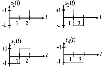
Find the convolution of above?
A1)
By inspection, the signals can be expressed in terms of the following two basis functions:


Note that the basis is orthogonal

Also note that each these functions have unit energy

We say that they form an orthonormal basis.
Q2) Find the homogenous solution for the difference equation y[n]- y[n-1]+
 y[n-2]=1+3-n. Given y[-2] = 0 and y[-1]=2
A2) For homogeneous solution
Y[n] = rn
rn- rn-1+
rn-1+ rn-2 = 0
rn-2(r2- r+
r+ ) = 0
) = 0
Solving above equation we get
r=  and r=1
Roots are distinct so the solution will be of the form
y[n] = p1 + p2
+ p2
y[n] = p12-n +
Particular Solution:
Input signal  | Particular solution  |
A constant | k |
 |  |
 |  |
 |  |
 |  |
The complete solution of any difference equation is the sum of homogeneous solution and the particular solution.
Q3) For the difference equation find the particular solution x[n] = 3n and y[n] = x[n]+ y[n-1]-
  y[n-2]?
A3) As x[n] = 3n
From table the particular solution will be y[n] = k3n
y[n] = x[n]+ y[n-1]-
  y[n-2]
k3nu(n) = 3nu(n)+ k 3n-1u(n-1)-
 k3n-2u(n-2)
Finding k for n≥2
K 32 = 32+ k 32-1-
 k 32-2
9k- k+
k+ k = 9
k = 9
k= 27/20
y[n]=  3n
3n
Q4) The continuous-time signal x(t) = cos(200πt) is used as the input for a CD converter with the sampling period 1/300 sec. Determine the resultant discrete-time signal x[n].
A4)
We know,
X[n] =x(nT)
= cos(200πnT)
= cos(2πn/3), where n= -1,0,1,2……
The frequency in x(t) is 200π rad/s while that of x[n] is 2π/3.
Q5) Determine the Nyquist frequency and Nyquist rate for the continuous-time signal x(t) which has the form of X(t) = 1+ sin(2000πt) + cos (4000πt)
A5)
The frequencies are 0, 2000π and 4000π.
The Nyquist frequency is 4000π rad/s and the Nyquist rate is 8000π rad/s.
Q6) Consider an analog signal 
A6)
The frequency in the analog signal

The largest frequency is

The Nyquist rate is

Q7) The analog signal 
- What is the Nyquist rate for this signal?
- Using a sampling rate
 . What is discrete time signal obtained after sampling?
 - What is analog signal
 we can reconstruct from the sample if we use ideal interpolation?
A7)
- The frequency of the analog signal are


- For


For  ,the folding frequency is
Hence  is not effected by aliasing
 Is changed by the aliasing effect
 Is changed by the aliasing effect
So that normalizing frequencies are

The analog signal that we can recover is

Q8) For given signal 
- Find the minimum sampling rate required to avoid aliasing.
- If
 , what is the discrete time signal after sampling?
 - If
 , what is the discrete time signal after sampling?
 - What is the frequency F of a sinusoidal that yields sampling identical to obtained in part c?
A8)
a. 
The minimum sampling rate is

And the discrete time signal is

b. If  , the discrete time signal is

c. If Fs=75Hz , the discrete time signal is

d. For the sampling rate 
 in part in (c). Hence

So, the analog sinusoidal signal is


Q9) Suppose a continuous-time signal x(t) = cos (Ø0t) is sampled at a sampling frequency of 1000Hz to produce x[n]: x[n] = cos(πn/4). Determine 2 possible positive values of Ø0, say, Ø1 and Ø2. Discuss if cos(Ø1t) or cos(Ø2t) will be obtained when passing through the DC converter.
A9)
Taking T= 1/1000s
Cos(πn/4) =x[n] = x(nT) = cos (Ø0n/1000)
Ø1 is easily computed as 
Ø1 = 250π
Ø2 can be obtained by noting the periodicity of a sinusoid:
 Ø2n/1000)
Ø2 = 2250π
Q10) Explain Sampling Theorem?
A10) In sampling the signal m(t) is multiplied with periodic pulse train. Let M(ω) the spectrum of the input signal be band limited with the maximum frequency of fm as shown in figure 1.
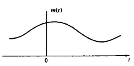
Figure: Spectrum of input Signal

Figure: (fs>2 fm)

Figure: (fs<2 fm)
The frequency spectrum of this signal when impulse sampled is plotted in figure 2 (for fs>2 fm). In figure 3 for (fs<2 fm). From figure 2 and figure 3 we can conclude that as long as fs≥2fm the original signal is preserved in the sampled signal and can be extracted from it by the low pass filter. This is known as Shannon’s Sampling theorem. This theorem states that the information contained in a signal is fully preserved in the sampled form as long as the sampling frequency is at least twice the maximum frequency contained in the signal.
Q11) Write Advantages of Digital over Analog signal processing.
A11)
1. Physical size of analog systems is quite large while digital processors are more compact and light in weight.
2. Analog systems are less accurate because of component tolerance ex R, L, C and active components. Digital components are less sensitive to the environmental changes, noise and disturbances.
3. Digital system is most flexible as software programs & control programs can be easily modified.
4. Digital signal can be stores on digital hard disk, floppy disk or magnetic tapes. Hence becomes transportable. Thus easy and lasting storage capacity.
5. Digital processing can be done offline.
6. Mathematical signal processing algorithm can be routinely implemented on digital signal processing systems. Digital controllers are capable of performing complex computation with constant accuracy at high speed.
7. Digital signal processing systems are upgradeable since that are software controlled.
8. Possibility of sharing DSP processor between several tasks.
9. The cost of microprocessors, controllers and DSP processors are continuously going down. For some complex control functions, it is not practically feasible to construct analog controllers.
10. Single chip microprocessors, controllers and DSP processors are more versatile and powerful.
Q12) Explain mapping between analog and digital frequencies.
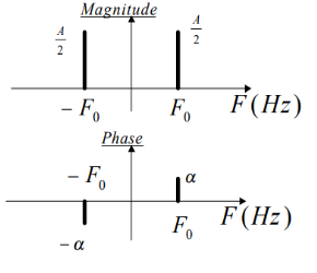
A12) A complex exponential signal, whether in continuous time or in discrete time, is completely determined by its amplitude A, phase α, and frequency which can be F0 Hz (or Ω0 rad/sec) in continuous time or w0 radians in discrete time, as in the following expressions:
X(t) =A ejα ejΩ0t = A ejα ej2πF0t
X[n] = A ejα ejw0n
When the signal is the superposition (ie sum) of two or more complex exponentials of different amplitudes and phases, we just add them in the plot and place them appropriately in frequency. So for example a sinusoidal signal, as
X(t) = A+ cos(2π F0t + α)
= (A/2) ejα ej2πF0t + (A/2) e-jα e-j2πF0t
Is represented by two complex exponentials with frequencies F0 and -F0 respectively, as shown in figure. Notice the appearance of the negative frequency -F0 which corresponds to the complex exponential with the same amplitude and opposite phase.
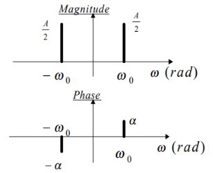
Similarly for the discrete time case.
A discrete time sinusoid
X[n] = A cos(w0n +α) = (A/2) ejα ejw0n + (A/2) e-jα e-jw0n
Q13) For the system with y(t)=x(-t), find whether the system is linear or not?
A13) To comment on linearity of system it should follow law of superposition. So, from model given below

Y(t)=ax1(-t)+bx2(-t)
Now from second model
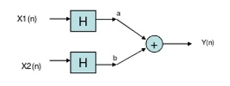
Y(t)= ax1(-t)+bx2(-t)
Since, output from both the model is same so system is linear.
Q14) For y(t)=cos[x(t)], comment whether it is time invariant or not?
A14) From model 1


Y(t)=cos[x(t-t0)]
From model 2


Y(t)=cos[x(t-t0)]
Since, time delay or advance in the input signal produces the corresponding change in the output. Hence, it is time invariant.
Q15) For y(t)=x(t2), is the system causal or anti causal?
A15) y(t)= x(t2)
If the output for any time depends on the future than its not causal. So, Let t=1
Y(1)=x(1)
t=2
y(2)=x(4)
Since, it depends on future values, so it is anti-causal.
Q16) For y(t)=x(t)+2. Comment whether system has memory or memoryless?
A16) For t=1
Y(1)=x(1)+2
For t=2
Y(2)=x(2)+2
So, for any value of t the output depends only on present input. Hence, it is memoryless.
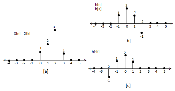
Q17) For sequence h[n]={ 1, 2 , 1, -1} determine the response of system with input signal x[n] = {1, 2 ,3 ,1}
A17)
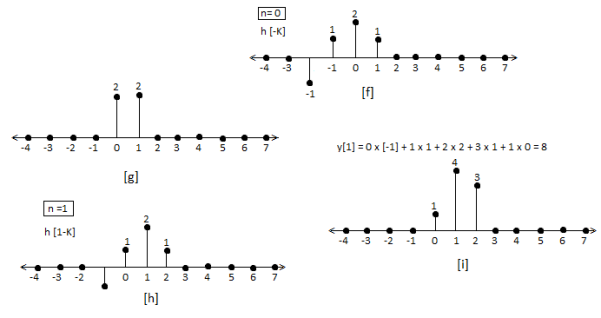
a) Finding x[k] and h[k] i.e n=k.
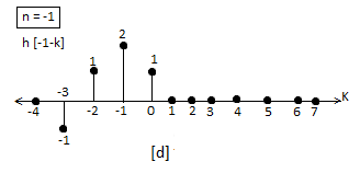
b) Folding h[k] we get h[-k].
c) Then shifting the above signal[-k] we get h[1-k]
d) Multiplying above signal h[1-k] with x[n].
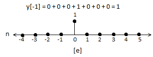
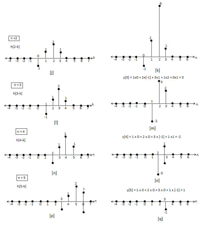
e) Again, incrementing h[1-k] by 1 we get h[2-k] multiplying with x[n].
f) Continuing this process till we get 0 for output y. In this case for n=5.
The graphical representation is shown below.
Q18) For h[n] = {1, 2, 1, -1}, x[n] = {1, 2, 3, 1}. Find x[n]*h[n]?
A18)
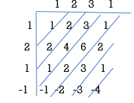
y[-1] = 1
y[0]= 2+2 = 4
y[1] = 1+4+3 = 8
y[2]= -1+2+6+1 = 8
y[3]= -2+3+2 = 3
y[4]= -3+1 = -2
y[5]= -1
y[n]= {1, 4, 8, 8, -2, -1}
The above sequence is the required convolution of x[n] and h[n].
Q19) Explain the types of discrete time systems?
A19) Even and Odd Signals
The even signals are symmetrical about Y-axis. They lie in first and second quadrants.
x[-n]=x[n]
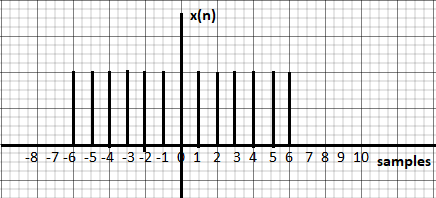
Fig: Even signal
The odd signals are symmetrical about origin. They lie in first and third quadrants.
x[-n]= -x[n]
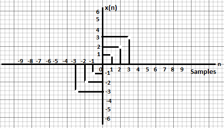
Fig: Odd signal
A signal having even and odd parts is mixed signal.
Periodic and Non-periodic signals:
A signal which repeats itself after a particular period of time is called as Periodic signal. The condition for any signal to be periodic is
x(n+N) = x(n)
Considering a cosine signal −
x(n)=A cos(2πf0n+θ) x(n)= A cos(2πf0n+θ)
x (n +N) = A cos (2πf0(n +N) +θ)
=A cos(2πf0n+2πf0N+θ) x (n+ N)
=A cos (2πf0(n +N) +θ) =A cos(2πf0n+2πf0N+θ)
=A cos(2πf0n+2πf0N+θ) = A cos(2πf0n+2πf0N+θ)
For the signal to become periodic, following condition should be satisfied;
X (n+ N) = x(n) x (n +N) = x(n)
A cos(2πf0n+2πf0N+θ) =A cos(2πf0n+θ)
A cos(2πf0n+2πf0N+θ) = A cos (2πf0n+ θ)
As, 2πf0N is an integral multiple of 2π
2πf0N=2πK
N=Kf0
Frequencies of discrete sinusoidal signals are separated by integral multiple of 2π.
Energy and Power Signals
Energy Signal
Energy of a discrete time signal is denoted as E. It can be written as
E = 
If each individual values of x(n)x(n) are squared and added, we get the energy signal. Here x(n) is the energy signal and its energy is finite over time i.e 0<E<∞
Power Signal
Average power of a discrete signal is represented as P. This can be written as
P = 

Q20) What is BIBO stability explain?
A20) BIBO stability stands for bounded input, bounded output stability. BIBO stability is the system property that any bounded input yields a bounded output. This is to say that as long as we input a signal with absolute value less than some constant, we are guaranteed to have an output with absolute value less than some other constant.
In order to understand this concept, we must first look more closely into exactly what we mean by bounded. A bounded signal is any signal such that there exists a value such that the absolute value of the signal is never greater than some value. Since this value is arbitrary, what we mean is that at no point can the signal tend to infinity, including the end behaviour.
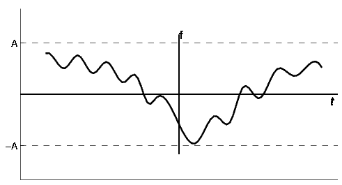
Fig: Discrete time BIBO Stable System
Now that we have identified what it means for a signal to be bounded, we must turn our attention to the condition a system must possess in order to guarantee that if any bounded signal is passed through the system, a bounded signal will arise on the output. It turns out that a continuous-time LTI system with impulse response h[n] is BIBO stable if and only if it is absolutely summable. That is
Discrete-Time Condition for BIBO Stability

In the z-domain is about as easy to demonstrate as it is for continuous-time signals in the Laplace domain. However, instead of the region of convergence needing to contain the jω-axis, the ROC must contain the unit circle. Consequently, for stable causal systems, all poles must be within the unit circle.