Back to Study material
Electronics Instruments and Measurement

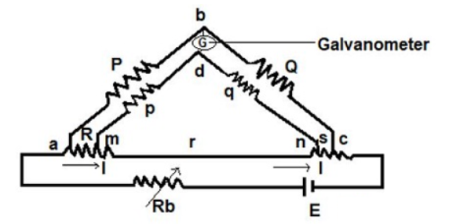
Unit-4DC Bridges Q1)Explain the construction of Kelvins double bridge? Kelvin double bridge is the modified version of Wheatstone’s bridge which measure resistance values in the range between 1 to 0.00001 ohms with high accuracy. It derives its name because it uses another set of ratio arm and a galvanometer to measure the unknown resistance value. The construction of Kelvin double bridge consists of 2 arms “P & Q”, “p & q” where the arm “p & q” is connected to one end of the galvanometer, at “d” and “P & Q” is connected to another end of the galvanometer, at ‘b’. This connection minimizes the effect of connecting lead and the unknown resistor R & a standard resistor S is placed between ” m and n”, and “a and c”.

Figure 1. Kelvins Double Bridge Q2) Derive the expression for Kelvins Double Bridge?

Derivation

The ratio p/q = P/Q,

Under the balanced condition current in galvanometer = 0

Potential difference at a & b = voltage drop between Eamd .

Eab = [P / P+Q ] Eac

Eac = I [ R + S + [( p+q)r] / [p+q+r]] …………(3)

Eamd = I [ R + (p / (p+q)) * {(p+q) r / (p+q+r)}]

Eac = I [ p r / ( p+q+r)] ………(4)

When galvanometer shows zero then

(P / P+Q) * I [ R + (p / (p+q)) * {(p+q) r / (p+q+r)} ] = I [ p r / (p+q+r)]

R = (P /R)* S + p r / (p+q+r) [ (P/Q) – (p/q)]

We know that P/Q = p/q

R = (P/Q) * S …….(5)

For obtaining perfect results, the arms ratio should be maintained equal and the thermo-electric electromagnetic field induced in the bridge while taking readings can be reduced by interchanging the polarity of the connection. Therefore the unknown resistance value can be obtained from the two arms.

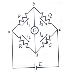
 Q3) Explain the construction of wheatstones bridge? Wheatstone bridge is an important device used in the measurement of medium resistances. The figure below shows the basic circuit of a Wheatstone bridge. It has four resistive arms, consisting of resistances P, Q R and S together with a source of emf that is battery and null detector galvanometer G or another sensitive current meter. The current through the galvanometer depends on the potential difference between points c and d.  The bridge is said to be balanced when there is no current through the galvanometer or when the potential difference across galvanometer is zero. The balanced condition occurs when voltage from point b to point a equals to voltage from point d to point b or by referring to the other battery terminal when the voltage from point d to point c equals the voltage from point b to point c.  

Figure 2. Wheatstone bridge for measurement of medium resistance. Q4) Derive the expression for wheat stone’s bridge?

For a balanced condition, we can write,

                                          I1 P = I2 R ---------------------(1)


For the galvanometer current to be zero, the following conditions also exist:


I1 = I3 = E/P+Q-----------------------------(2)

I2 = I4 = E/R+S ---------------------------------(3)

where E = emf of the battery
 

Combining the above three equations we get,


P/P+Q = R/R+S --------------------------------(4)


from which    Q.R = P.S ----------------------------------------------------------------(5)          

If three resistance are known, the unknown resistance can be obtained by  
 

                                    R = S*(P/Q)


where R is the unknown resistance, S is called the  'standard arm' of the bridge and P and Q are called the 'ratio arms'.

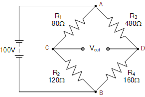
 Q5) The following unbalanced Wheatstone Bridge is constructed. Calculate the output voltage across points C and D and the value of resistor R4 required to balance the bridge circuit.

wheatstone bridge example

For the first series arm, ACB


Vc = R2/(R1+R2) x Vs


Vc = 120Ω/ 80Ω + 120 Ω x 100 = 60 volts


For the second series arm, ADB


VD = R4/(R3+R4) x Vs


VD = 160Ω/ 480Ω + 160Ω x 100 = 25 volts


The voltage across points C-D is given as:


Vout = VC – VD


Vout = 60 -25 = 35 volts


The value of resistor, R4 required to balance the bridge is given as:

R4 = R2R3/R1 = 120Ω x 480Ω/80Ω = 720 Ω

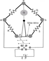
  Q6) Explain Carey-foster bridge?The Carey foster bridge circuit diagram is shown below. There are two units in the circuit
  • Bridge Unit
  • Testing Unit
  •  

    Figure 3. Carey Foster Bridge Circuit Carey Foster Bridge CircuitThe testing unit contains the power supply, galvanometer, and variable resistances which has to be measured. The DC supply is applied to eliminate the issues of battery discharge concerning time. From the figure, the bridge circuit is constructed with P, Q, R, and S resistances. P and Q are the known resistances used for comparison. R and S are unknown resistances to be measured. The slide wire with a length L is placed between the resistances R and S as shown in the figure. To equalize/equivalent the ratios of resistances P/Q and R/S, the values of P and Q can be adjusted. Slide the contact of the slide wire to equivalent the resistance ratio.Consider I1 to be the distance from the left side where the bridge is balanced. Interchanging the resistances R and S the bridge gets balanced by sliding the contact with distance I2.Q7) Derive the expression for the bridge?

    The switch is used to interchange the resistances R and S while testing. The galvanometer records zero when the bridge is balanced. The first bridge balance equation is,

    P/Q = (R+I1 r)/ [(S+(L+I1) r]

    Where r = resistance/unit length of the slide wire.

    Now interchange the resistances R and S. Then the balanced equation for the bridge circuit is given as,

    P/Q = (S+I2r)/[R+(L-I2)]

    For the first balance equation, we get,

    P/Q + 1 = [(R+I1r+ S+(L-I1) r]/[S+(L-I1) r] -------(1)

    P/Q = (R+S+I1r)/(S+(L-I1) r)

    We get a second bridge balance equation as

    P/Q + 1 = [ S + I2 r + R + (L-I1) r] / [R + (L-I2) r] -----------------------------(2)

    P/Q +1 = (S+ R+ Ir) /(R+(L-I2) r)

    From the above equations (1) and (2)

    S + (L-I1) r = R +(L-I1) r

    S-R = (I1-I2)

    At the bridge balance condition, the difference between the resistances S and R is equal to the difference of distance between the lengths l1 and l2 of the slide wire.

    Hence this type of bridge circuit is also called as Carey foster slide wire bridge circuit.

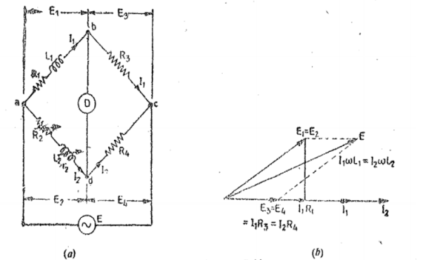
      Q8) Explain Maxwells bridge? This bridge circuit measures an inductance by comparison with a variable standard self-inductance. The connections and the phasor diagrams for balance conditions are shown in Fig. Let Li =unknown inductance of resistance Ri,L2=variable inductance of fixed resistance r2, Ra=variable resistance connected in series with inductor L2, and R3, R4=known non-inductive resistances.

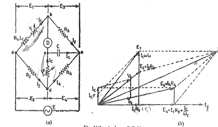
    Figure 4. Maxwells Inductance Bridge At balance L1 = R3/R4 L2 R1 = R3/R4 (R2+r2) Q9) Explain Anderson Bridge? This method is applicable for precise measurement of self-inductance over a very wide range of values. Fig. shows the connections. and the phasor diagram of the bridge for balanced conditions.

    Figure 5. Anderson Bridge 

    Let L1= self-inductance to be measured.

           R1 = resistance of self -inductor

           r 1 = resistance connected in series with self-conductor

          C = fixed standard capacitor

           R, R2, R3, R4 are known non inductive resistances.

    At balance I1=I3   and I2=Ic+I4

    I2R3 =Ic x 1/jwC      Ic = I1jwCR3

    Writing the other balance equation

    I1(r1+R1+jwL1) = I2R2+Icr    and Ic(r+1/jw) = (I2-Ic) R4.

    Substituting the values of Ic in the above equation we get

    I1(r1+C1+jwL1) =I2R2+I1jwC or I1(r1+R1-jwCR2r) =I2R2 ------(i)

    And jwCR2 I1(r+1/jwC) = (I2-I1jwcR2) R4 or I1(wCR2r+jwCR3R4+R3) = I2R4—(ii)

    From (i) and (ii) we get

    I1(r1+R1+jwL1-jwCR2r) = I1(R2R3/R4+jwCR2R3r/R4 +jwCR3R2)

    Equating real and imaginary terms

    R1=R2R3/R1 -r1

    And L1=CR3/R4[r(R4+R3) +R2R4

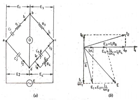
     Q10) Explain Schering Bridge ?

    Figure 6. Schering Bridge (low voltage)

    Let C1 = capacitor whose capacitance is to be determined

           r1 = series resistance representing the loss in the capacitor C1.

          C2 = standard capacitor.

          R3 = non-inductive resistance

    C4 = variable capacitor

    R4 = variable non-inductive resistance in parallel with variable capacitor C4.

    At Balance

    (r1+1/jwC1) (R4/ 1+jwC4R4) = 1/jwC2. R3

    ( r1 + 1/jwC1) R4 = R3 / jwC2 (1+jwC4R4)

    r1R4 – jR4/wC1 = -jR3/wC2 + R3R4C4/ C2

    Equating real and imaginary terms we obtain r1 = C4/C5 xR3

    And C1 = R4/R3 x C2

    Two independent balance equations are obtained if C4 and R4 are chosen as the variable elements

    Dissipation factor D1 = tan ɸ = w C1 r1 = w . R4/R3 . C2 . C4/C2 . R3 = wC4R4