Unit - 5
Compensators
Q1) Explain the need of compensation? What are the advantages of lead compensator?
A1)
For getting the required performance we need to adjust the design parameters and this is called compensation. To achieve the required output parameters a device called compensator is used. The compensators are mainly used to increase the steady state accuracy of system. These compensators minimise the overshoot. As these compensators are introduced in the system the transfer function changes and hence the performance specifications also change.
Let us discuss some of the advantages of the phase lead compensation-
- Due to the presence of phase lead network the speed of the system increases because it shifts gain crossover frequency to a higher value.
- Due to the presence of phase lead compensation maximum overshoot of the system decreases.
Q2) What is a phase lead compensator?
A2)
Phase – Lead Compensation:
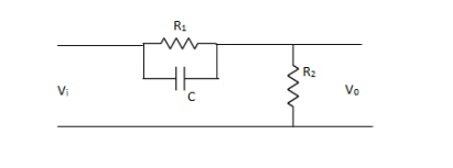
The phase of output voltage leads the phase of input voltage for the applied sinusoidal input. The circuit diagram is shown below. The transfer function is given as,

Fig. Phase Lead Compensation
Vo/Vi = α(1 + ST)/(1 + S α T)
Where, α = R2/R1 + R2 and α< 1
T = R1C
w = 1/T lower corner frequency due to zero.
w = 1/ αT upper corner frequency due to pole.
Mid frequency is given as,
wm = 1/T√ α
The maximum phase lead angle is φm
Φm = tan-1(1- α)/2√α = Sin-11- α/1 + α
Q3) Explain the phase lag compensation technique?
A3)
Phase Lag Compensation:
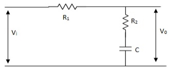
The phase of the output voltage lags the phase of the input voltage for applied sinusoidal input. The circuit diagram is shown below,

Fig. Phase Lag Compensation
Vo/Vi = 1 + ST/1 + SβT
Where, β = R1 + R2/R2, β> 1
T = R2C
w = 1/T upper corner frequency due to zero
w= 1/βT lower corner frequency due to pole
The mid frequency wm,
wm = 1/T√β
The maximum phase lead angle Φm
Φm = tan-11- β/2 √β
= sin-11 – β/1 + β
Advantages of Phase Lag Compensation
Let us discuss some of the advantages of phase lag compensation –
- Phase lag network allows low frequencies and high frequencies are attenuated.
- Due to the presence of phase lag compensation the steady state accuracy increases.
Disadvantages of Phase Lag Compensation
Some of the disadvantages of the phase lag compensation –
- Due to the presence of phase lag compensation the speed of the system decreases
Effect of Phase Lag Compensation
- Gain crossover frequency increases.
- Bandwidth decreases.
- Phase margin will be increase.
- Response will be slower before due to decreasing bandwidth, the rise time and the settling time become larger.
Q4) Explain the difference between phase lead and phase lag compensation techniques?
A4)
Phase Lead Network | Phase Lag Network |
1>. It is used to improve the transient response | 1>It is used to improve the Steady state response.
|
2>. It acts as a high pass filter. | 2>It acts as a low pass filter. |
3>. The system becomes fast as Bandwidth increases as rise Time decreases. | 3>The Bandwidth decreases through rise time the speed is slow.
|
4>. As the circuit acts as differentiator, signal to noise ratio is poor.
| 4>Signal to noise ratio is higher as it acts as integrator. |
5>. Maximum peak overshoot is reduced. | 5>It reduces steady state error thus improve the steady state accuracy |
Q5) Explain phase lead lag compensation techniques?
A5)
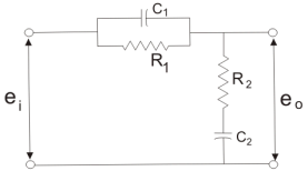
To overcome the disadvantages of lead and lag compensation, they are used together. As lead compensation does not provide phase margin but has fast response and lag compensation stabilize the system but does not provide enough bandwidth.

Fig. Lag-Lead Compensation
eo/ei = (1 + α ST1)/(1 + ST2)
Where, αT1 = R1C1
T2= R2C2
We can say in the lag-lead compensation pole is more dominating than the zero and because of this lag-lead network may introduces positive phase angle to the system when connected in series.
Q6) What are transducers?
A6)
Transducers are the devices that convert energy in one form into another form. Generally, the energy is in the form of a signal. Transducer is a term collectively used for both sensors and actuators.
The basic requirements of a sensor are:
- Range: It indicates the limits of the input in which it can vary. In case of temperature measurement, a thermocouple can have a range of 25 – 250 0C.
- Accuracy: It is the degree of exactness between actual measurement and true value. Accuracy is expressed as percentage of full range output.
- Sensitivity: Sensitivity is a relationship between input physical signal and output electrical signal. It is the ratio of change in output of the sensor to unit change in input value that causes change in output.
- Stability: It is the ability of the sensor to produce the same output for constant input over a period of time.
- Repeatability: It is the ability of the sensor to produce same output for different applications with same input value.
- Response Time: It is the speed of change in output on a stepwise change in input.
- Linearity: It is specified in terms of percentage of nonlinearity. Nonlinearity is an indication of deviation of curve of actual measurement from the curve of ideal measurement.
- Ruggedness: It is a measure of the durability when the sensor is used under extreme operating conditions.
- Hysteresis: The hysteresis is defined as the maximum difference in output at any measurable value within the sensor’s specified range when approaching the point first with increasing and then with decreasing the input parameter. Hysteresis is a characteristic that a transducer has in being unable to repeat its functionality faithfully when used in the opposite direction of operation.
Q7) What are the various types of sensors?
A7)
The scheme of classifying sensors can range from very simple to very complex. The stimulus that is being sensed is an important factor in this classification.
Some of the stimuli are
- Acoustic: Wave, spectrum and wave velocity.
- Electric: Current, charge, potential, electric field, permittivity and conductivity.
- Magnetic: Magnetic field, magnetic flux and permeability.
- Thermal: Temperature, specific heat and thermal conductivity.
- Mechanical: Position, acceleration, force, pressure, stress, strain, mass, density, momentum, torque, shape, orientation, roughness, stiffness, compliance, crystallinity and structural.
- Optical: Wave, wave velocity, refractive index, reflectivity, absorption and emissivity.
The sensors’ conversion phenomenon is also an important factor in classification of sensors. Some of the conversion phenomena are magneto electric, thermoelectric and photoelectric.
Based on the applications of sensors, their classification can be made as follows.
I. Displacement, Position and Proximity Sensors
- Resistive Element or Potentiometer
- Capacitive Elements
- Strain Gauged Element
- Inductive Proximity Sensors
- Eddy Current Proximity Sensors
- Differential Transformers
- Optical Encoders
- Hall Effect Sensors
- Pneumatic Sensors
- Proximity Switches
- Rotary Encoders
II. Temperature Sensors
- Thermistors
- Thermocouple
- Bimetallic Strips
- Resistance Temperature Detectors
- Thermostat
III. Light Sensors
- Photo Diode
- Phototransistor
- Light Dependent Resistor
IV. Velocity and Motion
- Pyroelectric Sensors
- Tachogenerator
- Incremental encoder
V. Fluid Pressure
- Diaphragm Pressure Gauge
- Tactile Sensor
- Piezoelectric Sensors
- Capsules, Bellows, Pressure Tubes
VI. Liquid Flow and Level
- Turbine Meter
- Orifice Plate and Venturi Tube
VII. IR Sensor
- Infrared Transmitter and Receiver Pair
VIII. Force
- Strain Gauge
- Load Cell
IX. Touch Sensors
- Resistive Touch Sensor
- Capacitive Touch Sensors
X. UV Sensors
- Ultraviolet Light Detector
- Photo Stability Sensors
- UV Photo Tubes
- Germicidal UV Detectors
All the sensors can be classified into two types based on the power or signal requirement. They are Active sensors and passive sensors.
Q8) Take any simple example using transducers and explain its working?
A8)
A Simple System using Transducers
A public addressing system is an example of a system using sensors and actuators.

It consists of a microphone, an amplifier and a loudspeaker. The sensor or the device with input function is a microphone. It senses the sound signals and transforms them into electrical signals. The amplifier receives these electrical signals and amplifies their strength.
The actuator or the device with output function is loudspeaker. It receives the amplified electrical signals from the amplifier and converts them back into sound signals but with more reach.
Q9) What are tachometers and list the difference between its types?
A9)
These are electromechanical devices which convert mechanical input at their shaft to corresponding electrical output. It is basically used to measure speed of motor. It has negative feedback. These devices are most commonly used to find speed of any rotating machine.
| D.C. Tachometer | A.C. Tachometer |
1. | They convert rotational speed into a proportional dc voltage. | They convert the rotational speed into a proportional ac voltage. |
2. | It uses a permanent magnet for producing magnetic field. It contains iron core rotor. | It works on principle of induction generator. |
3. | The permanent magnet controls the magnetic field therefore the induce voltage at terminal of armature is proportional to shaft speed. | The reference winding is supplied by reference voltage and the output voltage is induced across the output winding. |
4. | The polarity depends on direction of rotation. | The amplitude and phase depends on the direction of rotation. |
Q10) Explain the different types of errors in transducers?
A10)
Errors may rise from different sources and are classified as:
- Gross Errors
- Systematic errors
- Random Errors
Gross Errors: This class of errors covers human mistakes in reading instruments and recording and calculating measurement results. The responsibility of the mistake normally lies with the experimenter. The experimenter may grossly misread the scale.
Example
Due to some reasons, he might have read the temperature as 31.5 while the actual reading may be 21.5. He may transpose the reading while recording. For example, he may read 25.8 as 25.8. If human beings are involved gross errors will be committed.
Systematic Errors
These types of errors are divided into three categories:
- Instrument errors
- Environmental errors
- Observational errors
Instrumental Errors
These errors arise due to three main reasons:
(i) Due to inherent shortcomings in the instrument
(ii) Due to misuse of the instrument
(iii) Due to loading effects of instruments.
(1) Inherent short comings of instrument because of their mechanical structure. They may be due to construction, calibration or operation of the instruments or measuring device.
While making precision measurements we recognize the possibility of such errors as it is often possible to eliminate them by using the following methods:
(1) The procedure of measurement must be carefully planned. Substitution methods or calibration against standards may be used for the purpose.
(2) Correct factors should be applied after determining the instrumental errors.
(3) The instruments may be re-calibrated carefully.
(2) Misuse of instrument:
A good instrument used in an unintelligent way may give erroneous results.
Examples which may be cited for this misuse of instrument may be failure to adjust the zero of instruments, poor initial adjustments using leads too high a resistance and so on.
(3) Loading effects: One of the most common errors committed by beginners is the improper use of an instrument for measurement work. For example, a well calibrated voltmeter may give a misleading voltage reading when connected across high resistance circuit. However, when the same voltmeter is connected in low resistance circuit it may give dependable reading. These examples illustrate that the voltmeter has loading effect on the circuit.
Environmental errors will happen due to the outside situation of the measuring instruments. These types of errors mostly happen due to the temperature result, force, moisture, dirt, vibration otherwise because of the electrostatic field or magnetic. The remedial measures used to remove these unwanted effects include the following.
- The preparation should be finished to remain the situations as stable as achievable.
- By the instrument which is at no cost from these results.
- With these methods which remove the result of these troubles.
- By applying the computed modifications.
Observational Errors
The observational errors may occur due to the fault study of the instrument reading, and the sources of these errors are many. For instance, the indicator of a voltmeter retunes a little over the surface of the scale. As a result, a fault happens except the line of the image of the witness is accurately above the indicator. To reduce the parallax error extremely precise meters are offered with reflected scales.