Unit - 1
Basics of Fluid Power and Pumps
Q1) Define Fluid Power. Give advantages and disadvantages of fluid power system.
A1) “Fluid power is the technology that deals with the generation, control and transmission of forces and movement with the use of pressurized fluids in a confined system.”
Advantages of fluid power system:
- Fluid Power system provides wide range of force and pressure.
- Compared to other power systems, Fluid Power System is very effective in controlling of motion.
- The control if different components are very easy and can be automated easily.
- Force can be increased by controlling various control valves.
- Force or Torque is always constant at the end of transmission line irrespective of speed and other parameters.
- Provides very safe working conditions.
- High power – to – weight ratio.
Disadvantages of fluid power system:
- Fluid power system is not readily available.
- Cost of the components are high.
- Fluid power system works only between operating temperature range.
- Low efficiency.
- Requires regular maintenance.
Q2) What are the functions of hydraulic fluids?
A2) In fluid power systems, a hydraulic fluid has to perform various functions such as the following:
- Power transmission: To transmit power, which is the primary function.
- Lubrication: To lubricate various parts, so as to avoid metal-to-metal contact and reduce friction, wear and heat generation.
- Sealing: To seal the moving elements to avoid leakage.
- Cooling: To carry away the heat generated in the system and to dissipate the heat through a reservoir or a heat exchanger.
- Contaminant removal: To carry along the contaminations to the tank, where they can be removed through filters.
Q3) Explain concept of multiplication of force.
A3) The most useful feature of fluid power is the ease with which it is able to multiply force. This is accomplished by using an output piston that is larger than the input piston.
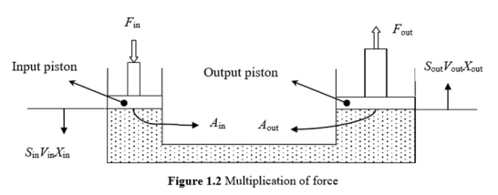
This system consists of an input cylinder on the left and an output cylinder on the right that is filled with oil. When the input force is Fin on the input piston, the pressure in the system is given by


Here to obtain the output force, the input force is multiplied by a factor that is equal to the ratio of the output piston area to the input piston area. If the output piston area is x times the input piston area, then the output force is x times the input force. Generally, the cross-sectional area of the piston is circular.
The area is given by

Hence, the above equation can be written as


Q4) Differentiate between positive displacement and non-positive displacement pump.
A4)
Positive Displacement Pumps | Non-positive Displacement Pumps |
The flow rate does not change with head | The flow rate decreases with head |
The flow rate is not much affected by the viscosity of fluid | The flow rate decreases with the viscosity |
Efficiency is almost constant with head | Efficiency increases with head at first and then decreases |
Q5) Explain construction and working of unbalanced vane pump with fixed delivery
A5) Unbalanced Vane Pump with Fixed Delivery
Construction
- The main components of the pump are the cam surface and the rotor.
- The rotor contains radial slots splined to drive shaft. The rotor rotates inside the cam ring.
- Each radial slot contains a vane, which is free to slide in or out of the slots due to centrifugal force.
- The vane is designed to mate with surface of the cam ring as the rotor turns.
- The cam ring axis is offset to the drive shaft axis.
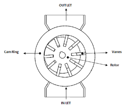
Fig. Unbalanced Vane pump with fixed delivery
Working
- When the rotor rotates, the centrifugal force pushes the vanes out against the surface of the cam ring.
- The vanes divide the space between the rotor and the cam ring into a series of small chambers.
- During the first half of the rotor rotation, the volume of these chambers increases, thereby causing a reduction of pressure.
- This is the suction process, which causes the fluid to flow through the inlet port.
- During the second half of rotor rotation, the cam ring pushes the vanes back into the slots and the trapped volume is reduced.
- This positively ejects the trapped fluid through the outlet port. In this pump, all pump action takes place in the chambers located on one side of the rotor and shaft, and so the pump is of an unbalanced design.
- The delivery rate of the pump depends on the eccentricity of the rotor with respect to the cam ring.
Q6) Explain construction and working of gear pump
A6) Construction
External gear pumps are the most popular hydraulic pumps in low-pressure ranges due to their long operating life, high efficiency and low cost. They are generally used in a simple machine.
The most common form of external gear pump is shown in Fig.
It consist of a pump housing in which a pair of precisely machined meshing gears runs with minimal radial and axial clearance.
One of the gears, called a driver, is driven by a prime mover. The driver drives another gear called a follower.
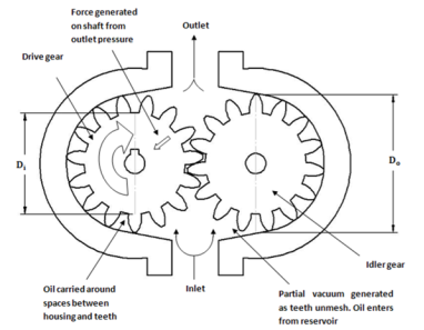
Fig. Operation of External Gear pump
Working
As the teeth of the two gears separate, the fluid from the pump inlet gets trapped between the rotating gear cavities and pump housing.
The trapped fluid is then carried around the periphery of the pump casing and delivered to outlet port.
The teeth of precisely meshed gears provide almost a perfect seal between the pump inlet and the pump outlet.
When the outlet flow is resisted, pressure in the pump outlet chamber builds up rapidly and forces the gear diagonally outward against the pump inlet.
When the system pressure increases, imbalance occurs. This imbalance increases mechanical friction and the bearing load of the two gears.
Hence, the gear pumps are operated to the maximum pressure rating stated by the manufacturer.
Q7) A gear pump has an outside diameter of 82.6 mm, inside diameter of 57.2 mm and a width of 25.4 mm. If the actual pump flow is 1800 RPM and the rated pressure is 0.00183 3 m /s, what is the volumetric efficiency?
A7)
We have,
Outside diameter Do = 82.6mm
Inside diameter Di = 57.2 mm
Width d = 25.4mm
Speed of pump N = 1800 RPM
Actual flow rate = 0.00183 3 m /s
Theoretical flow rate


QT = 2.125  10-3
10-3
Volumetric efficiency is

Q8) Write a note on pump performance characteristic curve
A8) Pump performance characteristics are first analyzed independently of the rest of hydraulic system and then as a part of the system. Both sets of data are valuable to the designer. Analyzing the pump by itself gives an indication of its capabilities and performance based on the speed of rotation, internal geometry, cost factors, etc., whereas analyzing pump performance in system essentially determines pump system compatibility. In the first case, the system designer may observe performance curves to see if a specific pump has the pressure and volume flow rate to operate a given set of actuators. In a second instance, the system designer may be computing the noise, vibration, cavitation and flow characteristics of a specific pump before or after installation to determine if the pump and existing system are compatible. Where the two are necessarily complimentary, in practice much of hands-on work is completed independently. Pump performance characteristics are interpreted from data in tabular form and then graphed.
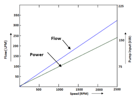
(a)
Figure (a) represents the relationship between input power and pump output flow of a variable displacement piston pump as a function of pump speed. Observe the linear relationship between the discharge flow and pump speed.
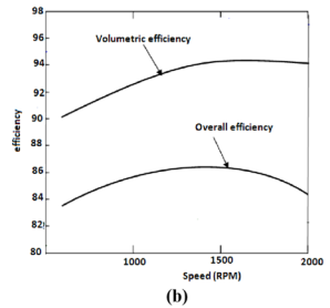
Figure (b) gives curves of overall and volumetric efficiencies as a function of speed.
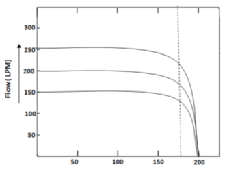
(c)
Performance curves of radial piston pump are given in Figure(c). Discharge flow of these pumps is nearly constant over a broad pressure range. Discharge flow can be varied infinitely between the point of inflection on the constant discharge portion of the curve and zero flow.
Q9) Define Mechanical, Volumetric and overall efficiencies.
A9)
Volumetric Efficiency: (ηV)
“It is the ratio of actual flow rate of the pump to the theoretical flow rate of the pump.”
Volumetric Efficiency (ηV) = | Actual Flow rate of pump |
Theoretical Flow rate of Pump | |
= | QA |
QT |
Volumetric efficiency (ηV) indicates the amount of leakage that takes place within the pump.
This is due to manufacture tolerances and flexing of the pump casing under designed pressure operating conditions.
For gear pumps, (ηV) = 80%–90%.
For vane pumps, (ηV) = 92%.
For piston pumps, (ηV) = 90%–98%.
Mechanical Efficiency: (ηm)
“It is the ratio of the pump output power assuming no leakage to actual power delivered to the pump.”
Mechanical Efficiency (ηm) = | Power output assuming no leakages |
Actual Power Delivered to pump | |
= | P QT |
TA N |
Where,
P is pump discharge pressure in Pa
QT is pump theoretical flow rate in m3/s
TA is Actual Torque delivered to pump in N-m
N is pump speed in rpm
Mechanical Efficiency can also be computed in terms of torques, as follows,
Mechanical Efficiency (ηm) = | Theoretical torque requirement for pump operations |
Actual torque Delivered to pump |
(ηm) = | Tth |
TA |
Tth= | Vd (m3) x P (Pa) | = | VdP | Nm |
2Π | 2Π |
And, TA = | 60 P |
2Π N |
Overall Efficiency: (ηo)
“It is defined as the ratio of actual power delivered by the pump to actual power delivered to the pump.”
Overall Efficiency (ηo) = | Actual Power delivered by pump |
Actual Power delivered to Pump |
Overall efficiency considers all energy losses and can be also represented mathematically as follows:
(ηo) = (ηv) (ηm)
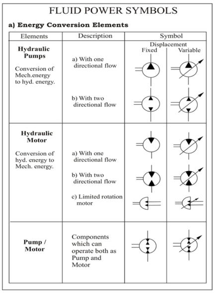
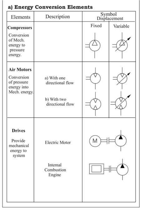
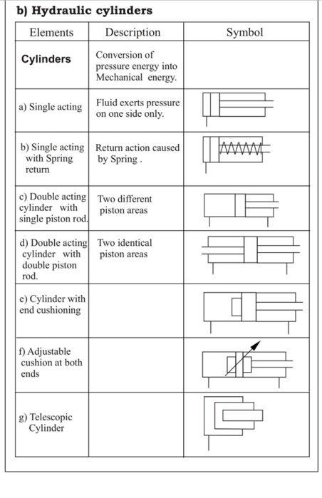
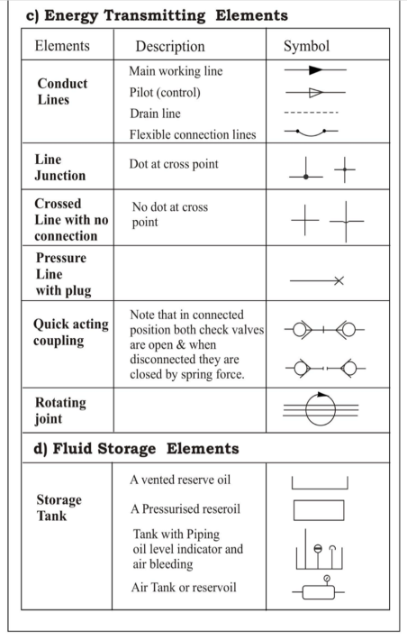
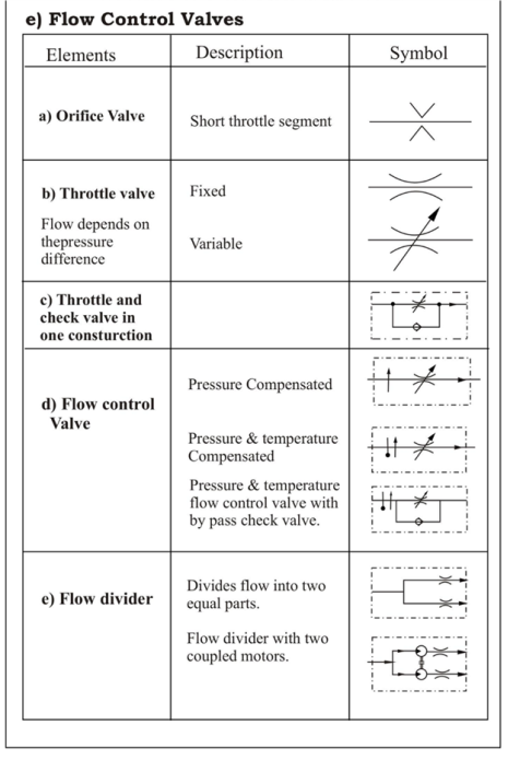
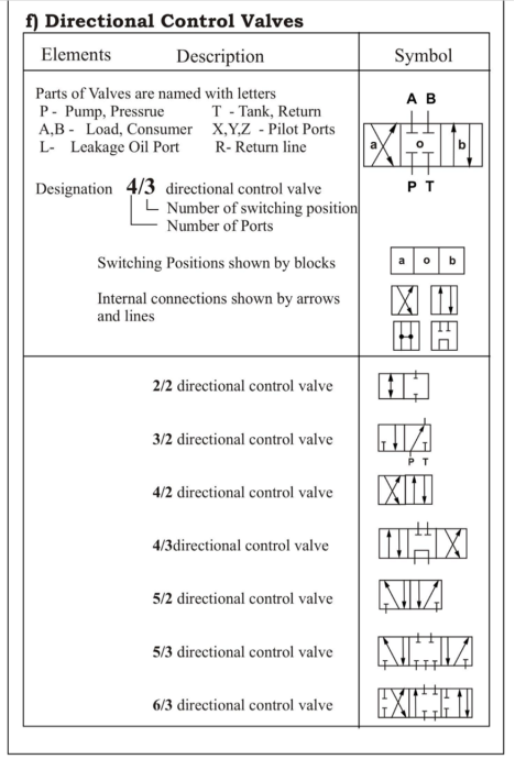
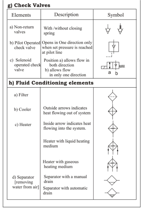
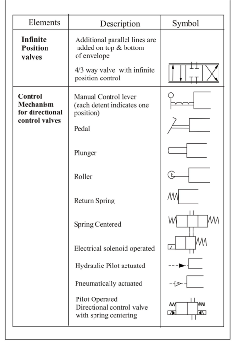
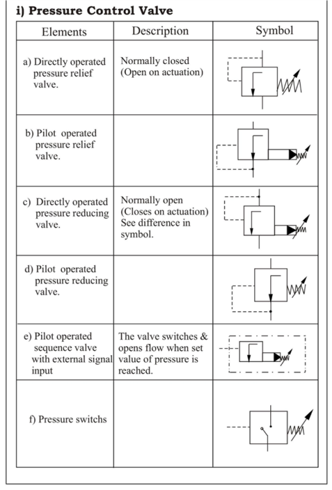
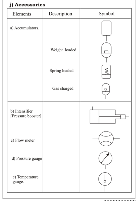
Q10) Give the symbols of the following elements.
(Note: All symbols are important)
A10)
Standard symbols:
