Unit - 2
Actuators and Power Unit
Q1) Explain Types of single acting cylinder
A1) Single Acting Cylinder:
It consists of a piston inside a cylindrical housing called barrel. On one end of the piston there is a rod, which can reciprocate. At the opposite end, there is a port for the entrance and exit of oil.
According to the type of return, single-acting cylinders are classified as follows:
- Gravity-return single-acting cylinder.
- Spring-return single-acting cylinder.
Gravity return Single Acting Cylinder:
Figure shows gravity-return-type single-acting cylinders.
- In the push type [Fig(a)], the cylinder extends to lift a weight against the force of gravity by applying oil pressure at the blank end. To retract the cylinder, the pressure is simply removed from the piston by connecting the pressure port to the tank.
- In pull-type gravity-return-type single-acting cylinder, the cylinder [Fig(b)] lifts the weight by retracting. The blank-end port is the pressure port and blind-end port is now the vent port. This cylinder automatically extends whenever the pressure port is connected to the tank.
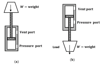
Fig. Gravity Return Single Acting Cylinder (a)push type (b)pull type
Spring Return Single Acting Cylinder:
A spring-return single-acting cylinder is shown in Fig.
- In push type [Fig(a)], the pressure is sent through the pressure port situated at the blank end of the cylinder. When the pressure is released, the spring automatically returns the cylinder to the fully retracted position. The vent port is open to atmosphere so that air can flow freely in and out of the rod end of the cylinder.
- [Fig(b)] shows a pull type spring-return single-acting cylinder. In this design, the cylinder retracts when the pressure port is connected to the pump flow and extends whenever the pressure port is connected to the tank. Here the pressure port is situated at the rod end of the cylinder.

Fig. Spring Return Single Acting Cylinder (a)Push type (b)Pull type
Q2) Write a note on Telescopic cylinder
A2) A telescopic cylinder (shown in Fig.) is used when a long stroke length and a short retracted length are required.
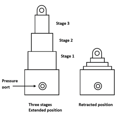
Fig. Telescopic Cylinder
The telescopic cylinder extends in stages, each stage consisting of a sleeve that fits inside the previous stage. One application for this type of cylinder is raising a dump truck bed. Telescopic cylinders are available in both single-acting and double-acting models.
- They generally consist of a nest of tubes and operate on the displacement principle.
- The tubes are supported by bearing rings, the innermost (rear) set of which have grooves or channels to allow fluid flow. The front bearing assembly on each section includes seals and wiper rings.
- Stop rings limit the movement of each section, thus preventing separation.
- When the cylinder extends, all the sections move together until the outer section is prevented from further extension by its stop ring.
- The remaining sections continue out-stroking until the second outermost section reaches the limit of its stroke;this process continues until all sections are extended, the innermost one being the last of all.
Q3) Explain Tandem Cylinder
A3)
- A tandem cylinder, shown in Fig., is used in applications where a large amount of force is required from a small-diameter cylinder.
- Pressure is applied to both pistons, resulting in increased force because of the larger area.
- The drawback is that these cylinders must be longer than a standard cylinder to achieve an equal speed because flow must go to both pistons.
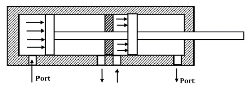
Fig. Tandem Cylinder
Q4) A 10 cm hydraulic cylinder has 5 cm diameter rod. If the cylinder receives flow at 100 LPM and 15 MPa. Find
1. Extension and retraction speeds
2. Extension and retraction load carrying capacities
A4)
Given:


To find :

a) 


b) 


Ans:
a) 
b) 
Q5) Write a note on Gear motor.
A5)
- A gear motor develops torque due to hydraulic pressure acting against the area of one tooth. There are two teeth trying to move the rotor in the proper direction, while one net tooth at the center mesh tries to move it in the opposite direction.
- In the design of a gear motor, one of the gears is keyed to an output shaft, while the other is simply an idler gear.
- Pressurized oil is sent to the inlet port of the motor. Pressure is then applied to the gear teeth, causing the gears and output shaft to rotate. The pressure builds until enough torque is generated to rotate the output shaft against the load.
- Most of the gear motors are bidirectional. Reversing the direction of flow can reverse the direction of rotation.
- The gear motors are simple in construction and have good dirt tolerance, but their efficiencies are lower than those of vane or piston pumps and they leak more than the piston units.
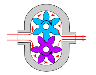
Fig. Hydraulic gear motor
Q6) Explain Vane motor in detail
A6)
- Unbalanced Vane motor consists of a circular chamber in which there is an eccentric rotor carrying several spring or pressure-loaded vanes.
- Because the fluid flowing through the inlet port finds more area of vanes exposed in the upper half of the motor, it exerts more force on the upper vanes, and the rotor turns counterclockwise.
- Close tolerances are maintained between the vanes and ring to provide high efficiencies.
- The displacement of a vane hydraulic motor is a function of eccentricity.
- The radial load on the shaft bearing of an unbalanced vane motor is also large because all its inlet pressure is on one side of the rotor.
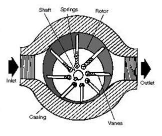
Fig. Unbalanced Hydraulic Vane Motor
Following figure shows the balanced vane motor.
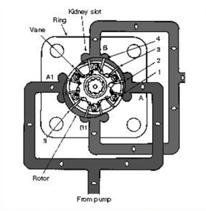
Fig. Balanced Hydraulic Vane Motor
- The radial bearing load problem is eliminated in this design by using a double-lobed ring with diametrically opposite ports.
- Side force on one side of bearing is canceled by an equal and opposite force from the diametrically opposite pressure port.
- The like ports are generally connected internally so that only one inlet and one outlet port are brought outside.
- The balanced vane-type motor is reliable open-loop control motor but has more internal leakage than piston-type and therefore generally not used as a servo motor.
Q7) A hydraulic motor has a 95 cm3, volumetric displacement. If it has a pressure rating of 130 bar and receives oil from a 0.001 m3/s theoretical flow rate pump, find the motor speed, theoretical torque and theoretical power in kW.
A7) Given: Use
 1)
1) 
P=130bar= 2)
2) 
 3) Power=
1) Speed : Theoretical flow rate can be given as,


2) Theoretical Torque:


3) Theoretical Power(kW):-


Power=P=13,000W =13kW
Q8) Write a note on cylinder mountings
A8) The various kinds of mountings normally used in industries are as follows
- Foot mounting:
It should be designed to give a limited amount of movement on one foot only to allow for thermal or load expansion. That is, the cylinder should be positively located or dowelled at one end only.
2. Rod-end flange or front flange mounting:
During the extend stroke, pressure in the hydraulic fluid acts on the cylinder-end cap, the force set up being transmitted to the front mounting flange through the cylinder body.
3. Rear flange, back flange or head-end flange mounting:
No stress is present in the cylinder owing to load on the extend stroke; only hoop stress is present. The load acts through the fluid onto the rear flange.
4. Trunnion mounting:
It allows angular movement. It is designed to take shear load only. Bearing should be as close to the cylinder body as possible.
5. Eye or clevis mounting:
There is a tendency for the cylinder to jack knife under load. Side loading of bearing must be carefully considered.
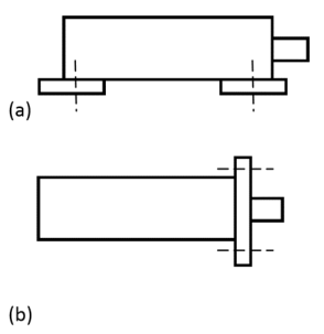
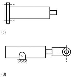
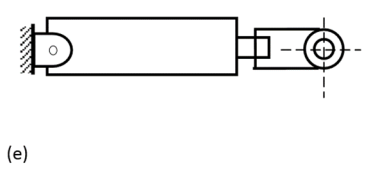
Fig. (a) Foot mounting; (b) rod-end flange or front flange mounting; (c) rear flange, back flange or head-end flange mounting; (d) trunnion mounting; (e) eye or clevis mounting.
Q9) Explain Cylinder cushioning
A9)
- For the prevention of shock due to stopping loads at the end of the piston stroke, cushion devices are used.
- Cushions may be applied at either end or both ends.
- They operate on the principle that as the cylinder piston approaches the end of stroke, an exhaust fluid is forced to go through an adjustable needle valve that is set to control the escaping fluid at a given rate.
- This allows the deceleration characteristics to be adjusted for different loads.
- When the cylinder piston is actuated, the fluid enters the cylinder port and flows through the little check valve so that the entire piston area can be utilized to produce force and motion.
A typical cushioning arrangement is shown in Fig.
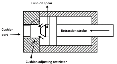
Fig. Hydraulic Cylinder with cushioning
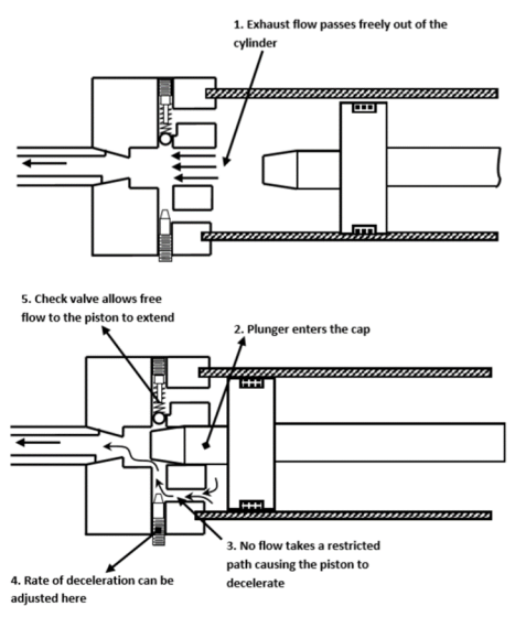
Fig. Operations of Cylinder Cushions
Q10) What are seals? Classify Seal.
A10) “Seals are used in hydraulic systems to prevent excessive internal and external leakage and to keep out contamination.”
Various functions of seals include the following:
- They prevent leakage – both internal and external.
- They prevent dust and other particles from entering into the system.
- They maintain pressure.
- They enhance the service life and reliability of the hydraulic system.
Classification of hydraulic seals
1. According to the method of sealing:
- Positive sealing: A positive seal prevents even a minute amount of oil from getting past. A positive seal does not allow any leakage whatsoever (external or internal).
- Non-positive sealing: A non-positive seal allows a small amount of internal leakage, such as the clearance of the piston to provide a lubrication film.
2. According to the relative motion existing between the seals and other parts:
- Static seals: These are used between mating parts that do not move relative to one another. Typical examples are flange gaskets and seals, o-rings, etc. These are relatively simple. They are essentially non-wearing and usually trouble-free if assembled properly.
- Dynamic seals: These are assembled between mating parts that move relative to each other. Hence, dynamic seals are subject to wear because one of the mating parts rubs against the seal.
3. According to geometrical cross-section:
- O-ring seal: O-ring is the most widely used seal for hydraulic systems. It is a molded synthetic rubber seal that has a round cross-section in its free state. O-ring can be used for the most static and dynamic conditions. It gives effective sealing through a wide range of pressures, temperatures and movements
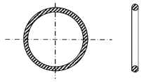
Fig. O-ring
- V-ring seal and U-ring seal: V- and U-ring seals are compression-type seals used in virtually in all types of reciprocating motion applications. These include piston rods and piston seals in pneumatic and hydraulic cylinder, press rank, jacks and seals on plungers and piston in reciprocating pumps. They are also readily suited to certain slow rotary applications such as valve stems. These packings (which can be molded into U-shapes as well as V-shapes) are frequently installed in multiple quantities for more effective sealing.

Fig. V-ring and U-ring Seal
- T-ring seal: T-ring seal isa dynamic seal that is extensively used to seal cylinder-pistons, piston rods and other reciprocating parts. It is made of synthetic rubber molded in the shape of the cross-section T and reinforced by backup rings on either side. The sealing edge is rounded and seals very much like an O-ring.
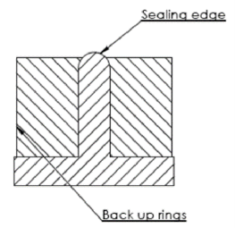
Fig. T-ring seal
- Piston rings: Piston rings are seals that are universally used for cylinder pistons. Metallic piston rings are made of cast iron or steel and are usually plated or given an outer coating of materials such as zinc phosphate or manganese phosphate to prevent rusting and corrosion. Piston rings offer substantially less opposition to motion than synthetic rubber (elastomer) seals.
Q11) Explain Filters and strainers.
A11)
- Filters:
They are devices whose primary function is the retention, by some fine porous medium, of insoluble contaminants from fluid. Filters are used to pick up smaller contaminant particles because they are able to accumulate them better than a strainer. Generally, a filter consists of fabricated steel housing with an inlet and an outlet. The filter elements are held in position by springs or other retaining devices. Because the filter element is not capable of being cleaned, that is, when the filter becomes dirty, it is discarded and replaced by a new one. Particle sizes removed by filters are measured in microns. The smallest sized particle that can be removed is as small as 1 µm. A strainer is a device whose function is to remove large particles from a fluid using a wire screen. The smallest sized particle that can be removed by a strainer is as small as 0.15 mm or 150 µm.
2. Hydraulic strainers:
A strainer is a coarse filter. Fluid flows more or less straight through it. A strainer is constructed of a fine wire mesh screen or of screening consisting of a specially processed wire of varying thickness wrapped around metal frames. It does not provide as fine a screening action as filters do, but offers less resistance to flow and is used in pump suction lines where pressure drop must be kept to a minimum. A strainer should be as large as possible or wherever this is not practical, two or more may be used in parallel.