Unit - 3
Fluid Power Control
Q1) What are different method of Actuation of DCV?
A1) Direction control valves may be actuated by a variety of methods. Actuation is the method of moving the valve element from one position to another.
There are four basic methods of actuation:
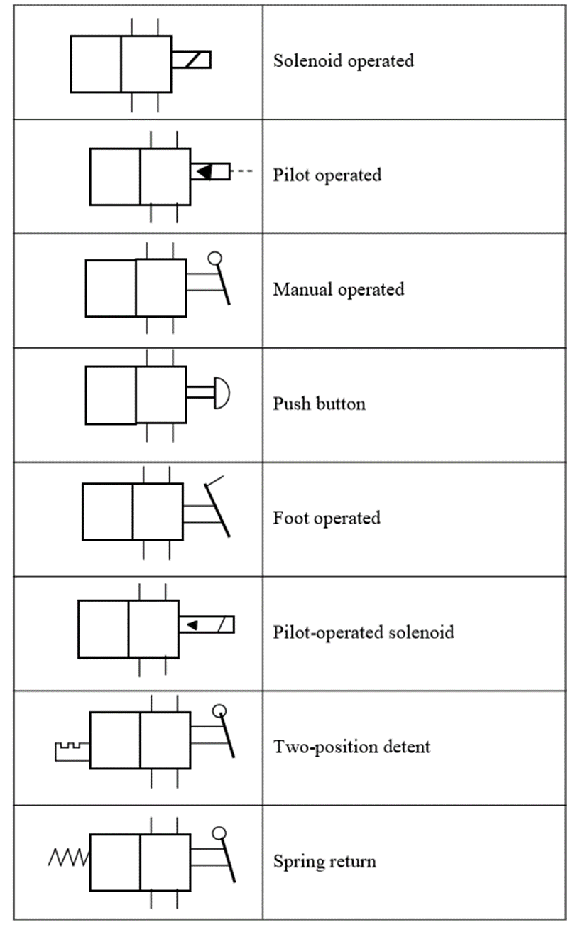
- Manually operated: In manually operated DCVs, the spool is shifted manually by moving a handle pushing a button or stepping on a foot pedal. When the handle is not operated, the spool returns to its original position by means of a spring.
- Mechanically operated: The spool is shifted by mechanical linkages such as cam and rollers.
- Solenoid operated: When an electric coil or a solenoid is energized, it creates a magnetic force that pulls the armature into the coil. This causes the armature to push the spool of the valve.
- Pilot operated: A DCV can also be shifted by applying a pilot signal (either hydraulic or pneumatic) against a piston at either end of the valve spool. When pilot pressure is introduced, it pushes the piston to shift the spool.
Several combinations of actuation are possible using these four basic methods. Graphical symbols of such combinations are given in Table
Q2) Explain with construction ball type check valve
A2)
- In Fig. Below, a light spring holds the ball against the valve seat.
- Flow coming into the inlet pushes the ball off the seat against the light force of the spring and continues to the outlet.
- A very low pressure is required to hold the valve open in this direction.
- If the flow tries to enter from the opposite direction, the pressure pushes the ball against the seat and the flow cannot pass through.
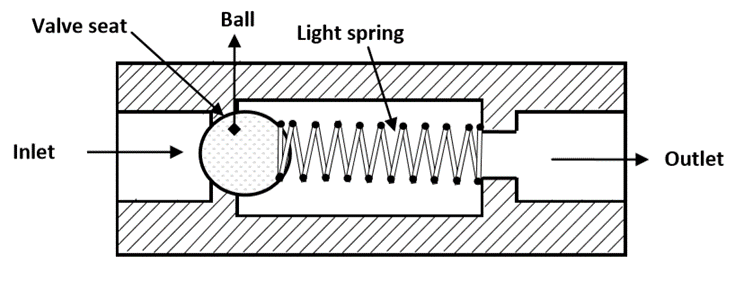
Fig. Ball-type Check Valve
Q3) What are Neutral positions? Give application of any one
A3)
- The four-way, two-position DCVs used in the previous two applications are sometimes impractical because they continually send pump flow and pressure to the actuator in one direction or the other.
- Many cylinder and motor applications require a third DCV position or neutral in which the actuator is subjected to pump pressure.
- Four-way three-position circuits are therefore used in many hydraulic circuits.
Many types of neutrals are available; the most common of them are as follows:
- Closed neutral.
- Tandem neutral.
- Float neutral.
- Open neutral.
- Regenerative neutral.
Application of 4/3 DCV (closed neutral) for controlling a double-acting cylinder
- The valve shown here is spring centered, which means that it always returns to the neutral position automatically when not actuated.
- For closed neutral, the pump line is blocked so that the flow must pass over the pressure relief valve the pressure is at the system maximum.
- This is wasteful thing because it generates power in the form of pressure and flow, but does not use it. The wasted energy in the system goes as heat. This is undesirable because the hydraulic fluid becomes thinner (less viscous) as it heats up.
- When the fluid becomes too thin, it does not lubricate effectively. This is the result of increased wear.
- The outlet lines to the cylinder are blocked, so the cylinder is held trimly in position. This is because the lines are full of hydraulic fluid that is incompressible.
- This type of neutral could also be used to control a motor. Just like cylinder, the motor is held tired in position when the valve is in the neutral.
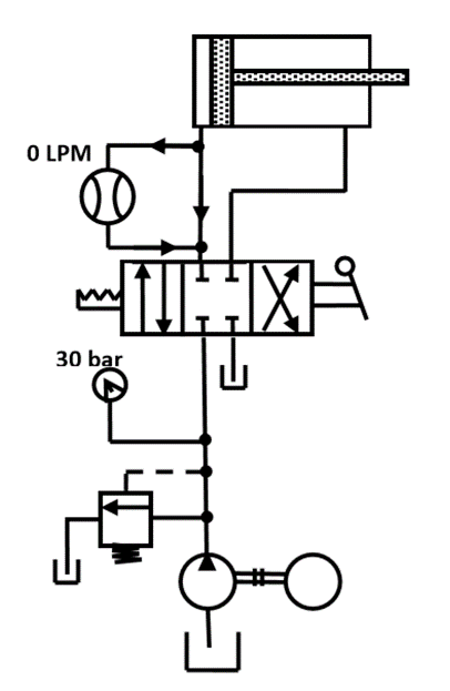
Fig. Application of closed neutral position in 4/3 DCV
Q4) Explain pressure compensated flow control valve in detail
A4) Schematic diagram of a pressure compensated flow-control valve is shown in Fig
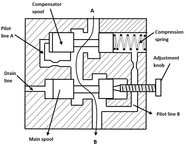
Fig. Pressure Compensated Flow Control Valve
- A pressure-compensated flow-control valve consists of a main spool and a compensator spool. The adjustment knob controls the main spool’s position, which controls the orifice size at the outlet. The upstream pressure is delivered to the valve by the pilot line A.
- Similarly, the downstream pressure is ported to the right side of the compensator spool through the pilot line B.
- The compensator spring biases the spool so that it tends toward the fully open position.
- If the pressure drop across the valve increases, that is, the upstream pressure increases relative to the downstream pressure, the compensator spool moves to the right against the force of the spring.
- This reduces the flow that in turn reduces the pressure drop and tries to attain an equilibrium position as far as the flow is concerned.
- In the static condition, the hydraulic forces hold the compensator spool in balance, but the bias spring forces it to the far right, thus holding the compensator orifice fully open.
- In the flow condition, any pressure drop less than the bias spring force does not affect the fully open compensator orifice, but any pressure drop greater than the bias spring force reduces the compensator orifice.
- Any change in pressure on either side of the control orifice, without a corresponding pressure change on the opposite side of the control orifice, moves the compensator spool.
- Thus, a fixed differential across the control orifice is maintained at all times. It blocks all flow in excess of the throttle setting.
- As a result, flow exceeding the preset amount can be used by other parts of the circuit or return to the tank via a pressure-relief valve.
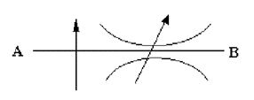
Fig. Graphical Symbol of pressure compensated flow control valve
Q5) What do you understand by temperature compensation?
A5)
- Performance of flow-control valve is also affected by temperature changes which changes the viscosity of the fluid.
- Therefore, often flow-control valves have temperature compensation.
- When the temperature increases, the viscosity of oil decreases, this leads to increased velocity, thus increased flow.
- Now to keep the flow constant, the flow area must be reduced.
- This is achieved by using special alloy rod, which expands and contracts on even small variation in temperature.
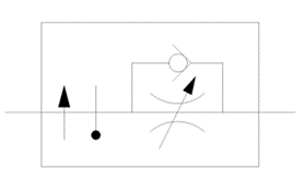
Fig. Symbol of Pressure and temperature compensated flow control valve
Q6) Draw schematically a pilot operated relief valve and explain its function
A6)
A pilot-operated pressure-relief valve consists of a small pilot relief valve and main relief valve as shown in Fig
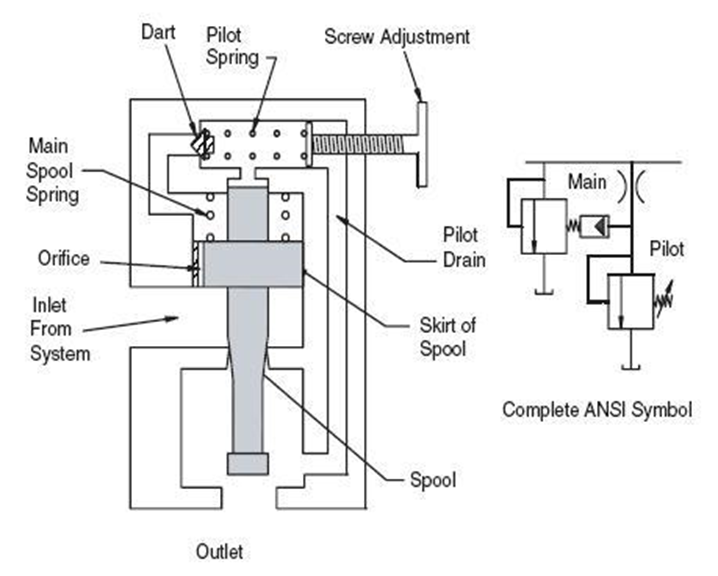
Fig. Compound Pressure Relief Valve
- The pilot-operated pressure-relief valve has a pressure port that is connected to the pump line and the tank port is connected to the tank. The pilot relief valve is a poppet type.
- The main relief valve consists of a piston and a stem. The main relief piston has an orifice drilled through it.
- The piston has equal areas exposed to pressure on top and bottom and is in a balanced condition due to equal force acting on both the sides.
- It remains stationary in the closed position. The piston has a light bias spring to ensure that it stays closed.
- When the pressure is less than that of relief valve setting, the pump flow goes to the system. If the pressure in the system becomes high enough, it moves the pilot poppet off its seat.
- A small amount of flow begins to go through the pilot line back to the tank.
- Once flow begins through the piston orifice and pilot line, a pressure drop is induced across the piston due to the restriction of the piston orifice.
- This pressure drop then causes the piston and stem to lift off their seats and the flow goes directly from the pressure port to the tank.
Q7) Explain the function of the direct operated sequence valve
A7) A sequence valve is a pressure control valve that is used to force two actuators to be operated in sequence. They are similar to pressure relief valves. The symbol for sequence valve is as shown below.
Instead of sending flow back to tank, a sequence valve allows flow to a branch circuit, when a preset pressure is reached. The check valve allows the sequence valve to be bypassed in the reverse direction. The component enclosure line indicates that the check valve is an integral part of the component. The sequence valve has an external drain line; therefore a line must be connected from the sequence valve’s drain port to the tank.
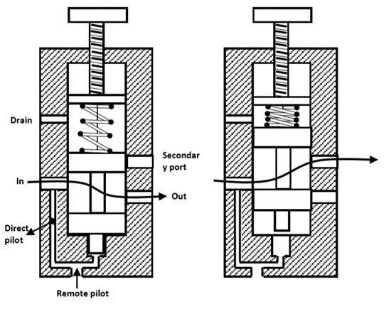
Fig. Sequence Valve
Q8) What are the difference between the relief valve and the sequence valve
A8) A sequence valve is a pressure control valve that is used to force two actuators to be operated in sequence. They are similar to pressure relief valves. Instead of sending flow back to tank, a sequence valve allows flow to a branch circuit, when a preset pressure is reached.
Q9) Explain the application of counterbalance valve
A9) Figure illustrates the use of a counterbalance or back-pressure valve to keep a vertically mounted cylinder in the upward position while the pump idles, that is, when the DCV is in its center position. During the downward movement of the cylinder, the counterbalance valve is set to open at slightly above the pressure required to hold the piston up (a check valve does not permit flow in this direction).
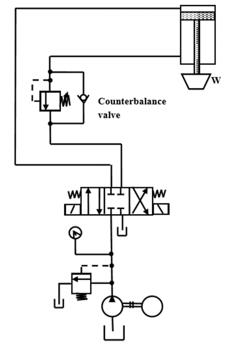
Fig. Application of Counter balance valve
Q10) What is the advantage of using an unloading circuit, when feed and speed of a machine need to be varied?
A10)
- When high speed is required during air cutting, high flow pump can be used to get the rapid extension and cutting time is saved.
- When cutting is taking place ( torque requirement is high), low flow pump can be used
- This circuit eliminates the necessity of having a very expensive high pressure, high flow pump.