Unit - 5
Pneumatics – Components, Control Valves and Circuits
Q1) Differentiate between hydraulic and pneumatic systems
A1)
Sr. No. | Hydraulic System | Pneumatic System |
1 | It employs a pressurized liquid as fluid | It employs a compressed gas usually air as a fluid |
2 | Oil hydraulics system operates at pressures upto 700 bar. | Pneumatics systems usually operate at 5 to 10 bar. |
3 | Generally designed for closed systems | Pneumatic systems are usually designed as open system |
4 | System get slow down of leakage occurs | Leakage does not affect the system much more |
5 | Valve operations are difficult | Easy to operate the valves |
6 | Heavier in weight | Light in weight |
7 | Pumps are used to provide pressurized liquids | Compressors are used to provide compressed gas |
8 | System is unsafe to fire hazards | System is free from fire hazards |
9 | Automatic lubrication is provided | Special arrangements for lubrication needed. |
Q2) Write down advantages and disadvantages of pneumatic system
A2) Advantages of Pneumatic system
- Low inertia effect of pneumatic components due to low density of air. o Pneumatic Systems are light in weight.
- Operating elements are cheaper and easy to operate
- Power losses are less due to low viscosity of air
- High output to weight ratio
- Pneumatic systems offers a safe power source in explosive environment
- Leakage is less and does not influence the systems. Moreover, leakage is not harmful.
Disadvantages of Pneumatic systems
- Suitable only for low pressure and hence low force applications
- Compressed air actuators are economical up to 50 kN only.
- Generation of the compressed air is expensive compared to electricity
- Exhaust air noise is unpleasant and silence has to be used.
- Rigidity of the system is poor o Weight to pressure ratio is large o Less precise. It is not possible to achieve uniform speed due to compressibility of air.
- Pneumatic systems is vulnerable to dirt and contamination.
Q3) Explain with neat sketch piston compressor
A3) Piston compressors are by far the most common type of compressor, and a basic single cylinder form is shown in Figure.
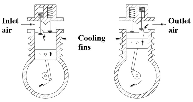
Fig. Single Cylinder Piston Compressor
- As the piston descends during the inlet stroke, the inlet valve opens and air is drawn into the cylinder.
- As the piston passes the bottom of the stroke, the inlet valve closes and the exhaust valve opens allowing air to be expelled as the piston rises.
- The valves are similar to valves in an internal combustion engine.
- In practice, spring-loaded valves are used, which open and close under the action of air pressure across them.
- Piston compressors which go direct from atmospheric to required pressure in a single operation. This is known as a single stage compressor.
- A single cylinder compressor gives significant pressure pulses at the outlet port. This can be overcome to some extent by the use of a large receiver, but more often a multi-cylinder compressor is used.
- If the exit pressure is above about 5 bar in a single- acting compressor, the compressed air temperature can rise to over 200~ and the motor power needed to drive the compressor rises accordingly.
- For pressures over a few bar it is far more economical to use a multistage compressor with cooling between stages. Figure shows an example.
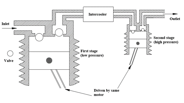
Fig. Multi stage Piston Compressor
- As cooling (undertaken by a device called an intercooler) reduces the volume of the gas to be compressed at the second stage there is a large energy saving.
- Normally two stages are used for pneumatic pressures of 10 to 15 bar, but multistage compressors are available for pressures up to around 50 bar.
Q4) Write a note on Air Filter
A4) The purpose of the air filter is to clean the compressed air of all impurities and any condensate it contains.
Function of air filters
- To remove all foreign matter and allow dry and clean air flow without restriction to regulator and then to the lubricator
- To condensate and remove water from the air
- To arrest fine particles and all solid contaminants from air
Filters are available in wide range starting from a fine mesh wire cloth (which strains heavy foreign particles) to elements made of synthetic material (which removes very small particles)
Usually in line filter elements can remove contaminants in the 5-50 micron range.
The construction of typical cartridge type filter along with graphical symbols is shown in Figure
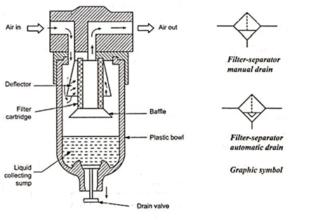
Fig. Typical Air Filter
- It consists of filter cartridge, Deflector, bowl, water drain valve. Filter bowl is usually made of plastic and transparent.
- For pressure more than 10 bar, bowl may be made of brass.
- Air enters the inlet port of the air filter through angled louvers. This causes the air to spin as it enters the bowl. The centrifugal action of the rotating air causes the larger pieces of dirt and water particles to be thrown against the inner wall of the filter bowl. These contaminants then flow down into the bottom of the filter bowl.
- A baffle prevents turbulent air from splashing water on to the filter element. The air, which has been pre-cleaned in this way, then passes through the filter element, where the fine dirt particles are filtered out. The size of the dirt particles which can be filtered out depends on mesh size of filter element (usually 5-50 microns). The compressed air then exits through the outer port.
- The pressure difference between inlet and outlet will indicate the degree to which the filter element is clogged. Commercially available filters have many additional features like automatic drain facility, coalescing type filter element, service life indicator etc.
Q5) What is the function of dryer? Explain any one in detail
A5) Function of dryer is to lower the dew point of the compressed air by removing the moisture from it. For simple applications, to remove excess humidity, we need simple after cooler, an air receiver, and a filter with condensate traps.
Types of Dryer
Generally four basic types of air dryers are used in Industries.
- Absorption type dryer
- Adsorption type dryer
- Refrigeration dryer
Absorption type dryer
Schematic diagram of absorption dryer is shown in Figure
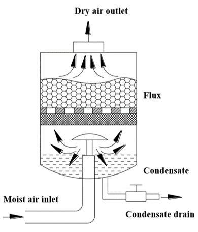
Fig. Absorption Dryer
- Absorption drying is a purely chemical process.
- The moisture in the compressed air forms a compound with drying agent like phosphoric pentaoxide in the tank.
- This causes the drying agent to break down.
- It is then discharged in the form of a fluid at the base of the tank.
- Oil Vapour and oil particles are also separated in the absorption dryer. Large quantities of oil have an effect on the efficiency of the dryer.
- Therefore it is advisable to include a fine filter in front of the dryer.
Q6) Explain Ball seat DCV
A6) Ball seat valve.
- In a poppet valve, discs, cones or balls are used to control flow.
- Figure shows the construction of a simple 2/2 normally closed valve.
- If the push button is pressed, ball will lift off from its seat and allows the air to flow from port P to port B.
- When the push button is released, spring force and air pressure keeps the ball back and closes air flow from port P to port B.
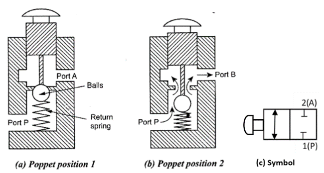
Fig. 2/2 Ball seat poppet valve
Q7) What is shuttle Valve?
A7)
- It is also known as a double control valve or double check valve. A shuttle valve has two inlets and one outlet.
- At any one time, flow is shut off in the direction of whichever inlet is unloaded and is open from the loaded inlet to the outlet.
- A shuttle valve may be installed, for example, when a power unit (cylinder) or control unit (valve) is to be actuated from two points, which may be remote from one other.
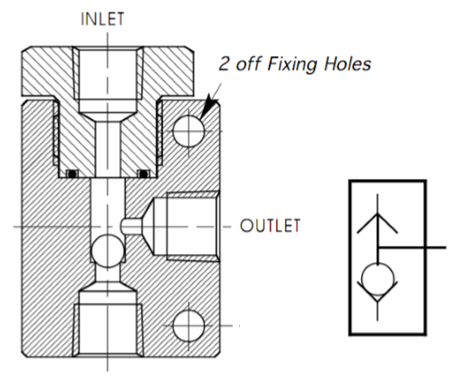
Fig. Shuttle valve
Q8) Write a note on Quick Exhaust Valve with its application.
A8)
- A quick exhaust valve is a typical shuttle valve.
- The quick exhaust valve is used to exhaust the cylinder air quickly to atmosphere. Schematic diagram of quick exhaust valve is shown in Figure.
- In many applications especially with single acting cylinders, it is a common practice to increase the piston speed during retraction of the cylinder to save the cycle time.
- The higher speed of the piston is possible by reducing the resistance to flow of the exhausting air during the motion of cylinder.
- The resistance can be reduced by expelling the exhausting air to the atmosphere quickly by using Quick exhaust valve.
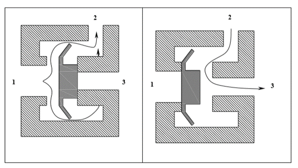
Fig. Quick Exhaust Valve
The construction and operation of a quick exhaust valve is shown in Figure.
- It consist of a movable disc (also called flexible ring) and three ports namely, Supply port 1, which is connected to the output of the final control element (Directional control valve).
- The Output port, 2 of this valve is directly fitted on to the working port of cylinder.
- The exhaust port, 3 is left open to the atmosphere
Forward Motion: During forward movement of piston, compressed air is directly admitted behind the piston through ports 1 and 2 Port 3 is closed due to the supply pressure acting on the diaphragm. Port 3 is usually provided with a silencer to minimize the noise due to exhaust.
Return Motion: During return movement of piston, exhaust air from cylinder is directly exhausted to atmosphere through opening 3 (usually larger and fitted with silencer) .Port 2 is sealed by the diaphragm. Thus exhaust air is not required to pass through long and narrow passages in the working line and final control valve
Typical applications of quick exhaust valves for single acting and double acting cylinders are shown in Figure.
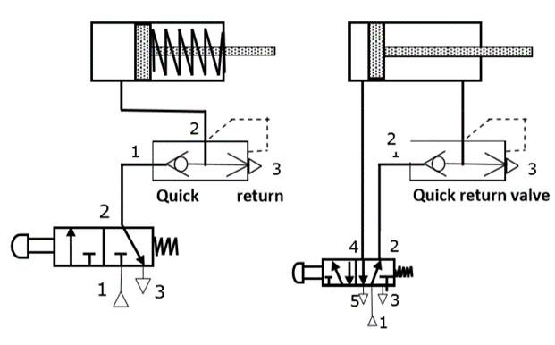
Fig. Application of Quick Exhaust Valve
Q9) Explain Tandem Cylinder in detail
A9)
- Tandem cylinders are two separate double acting air cylinders arranged in line to one cylinder body so that the power generated by the two is added together, thereby approximately doubling the piston output.
- A tandem cylinder is used in applications where a large amount of force is required from a small-diameter cylinder.
- Basically, a tandem cylinder is simply two or more separate cylinders stacked end to end in a unit and with all the pistons mounted on a common piton rod.
- Pressure is applied to both pistons, resulting in increased force because of the larger area.
- Tandem cylinders are used where large output force is required with appreciable saving in bulk and weight.
- Tandem cylinders are employed where a small diameter of the assembly is required.
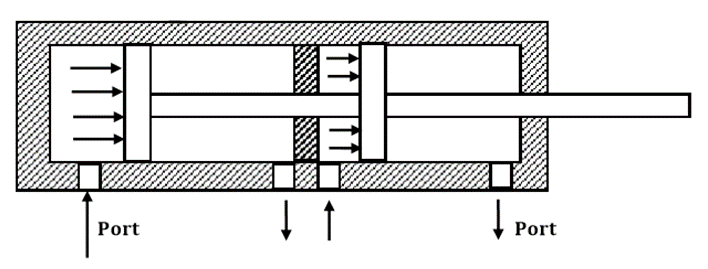
Fig. Tandem Cylinder
Q10) Explain Pneumatic OR Valve
A10)
- Shuttle valve is also known as double control valve or double check valve.
- At any one time, flow is shut off in the direction of whichever inlet is unloaded and is open from the loaded inlet to the outlet. This valve is also called an OR valve.
- A shuttle valve may be installed for example, when the cylinder or valve is to be actuated from two points, which may be remote from one another.
- The single acting cylinder in Figure can be operated by two different circuits.
- Examples include manual operation and relying on automatic circuit signals, that is, when either control valve 1 or control valve 2 is operated, the cylinder will work. Therefore, the circuit in Figure possesses the OR function.
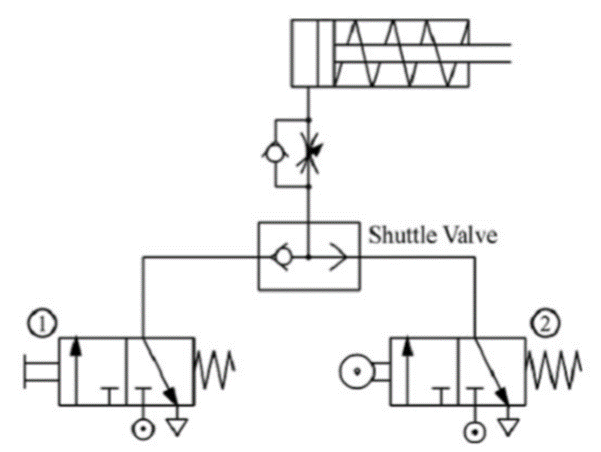
Fig. Control of a single acting cylinder using OR valve
Q11) Explain Pneumatic AND Valve
A11)
- Two Pressure valve is used as a AND valve in Pneumatics
- A two pressure valve requires two pressurized inputs to allow an output from itself.
- Another name for an AND function is interlock control.
- This means control is possible only when two conditions are satisfied.
- A classic example is a pneumatic system that works only when its safety door is closed and its manual control valve is operated.
- The flow passage will open only when both control valves are operated.
- Figure shows the circuit diagram of an AND function circuit.
- The cylinder will work only when both valve 1 and 2 are operated.
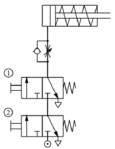
Fig. Control of a single acting cylinder using AND valve