Unit - 7
Flow through Pipes
Q1) Explain the forces exerted on the immersed bodies.
A1) When a fluid is flowing over a stationary body, a force is exerted by the fluid on the body. Similarly, when a body is moving in a stationary fluid, a force is exerted by the fluid on the body.
Also, when the body and fluid both are moving at different velocities, a force is exerted by the fluid on the body.
Some of the examples of the fluids flowing over stationary bodies or bodies moving in a stationary fluid are:
1. Flow of air over buildings
2. Flow of water over bridges
3. Submarines, ships, airplanes and automobiles moving through water or air.
Total pressure: The total pressure is the sum of static pressure and dynamic pressure and the gravitational potential energy per unit volume. It is therefore sum of mechanical energy per unit volume in a fluid.
PTotal= P1+P2+P3+….
Total pressure on the immersed surface: The total pressure exerted by a liquid on an immersed surface may be:
- Horizontal
- Vertical
- Inclined
Q2) Discuss the concept of separation.
A2) According to Bernoulli’s principle, a change in kinetic energy is directly linked to a change in static pressure. In this case, the increase in kinetic energy is at the expense of the pressure (energy). The static pressure thus decreases to a minimum up to the thickest point of the cylinder. The pressure gradient in x-direction is negative in this area (∂p∂x<0).
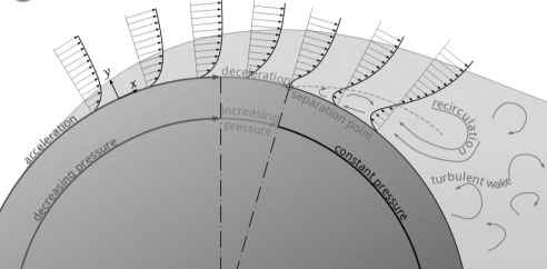
Figure: Flow of fluid in air craft
Now the effective cross-section of the flow increases, as the cylinder cross-section decreases (the flow has more space, so to speak). The flow slows down and the static pressure rises again in the x-direction to finally reach the level of the atmosphere (∂p∂x>0). This pressure gradient acting against the actual direction of flow is called adverse pressure gradient. Note that this pressure gradient is mathematically positive and not negative, as the pressure increases in the positive x-direction.
Depending on the shape of the body, the resulting adverse pressure gradient can become very large due to the decrease in speed and the boundary layer thickness increases significantly. In the case of the cylinder, the adverse pressure gradient even becomes so large that the flow is forced back against the actual flow direction. This results in a backflow area and the laminar flow detaches itself from the contour at this point. A so-called turbulent wake is formed behind the body.
From a mathematical point of view, flow separation begins at that point on the surface where the flow is pushed back so strongly that the velocity gradient in the y-direction becomes zero (there is now an inflection point in the velocity profile!). According to Newton’s law of fluid friction, this means that the shear stress at the wall, the so-called wall shear stress τw, also becomes zero.
 condition for flow separation.
The separation of the boundary layer takes place at the point where the wall shear stress becomes zero. The fluid particles follow the pressure drop which acts against the main flow direction (recirculation area).
Q3) Explain drag force.
A3) Drag Force (D) is defined as the force that resists the motion of a body with fluid. If the motion of the body exists in the fluid-like air it is known as aerodynamic drag. And, if the fluid is water it is known as hydrodynamic drag. The drag force always acts in the opposite direction to the flow of fluid.
When a body moves through a moving a fluid, it is acted upon by two forces exerted by the flow upon it: -
- Shear Force.
- Pressure Force.
Resolving these forces into horizontal and vertical components: -
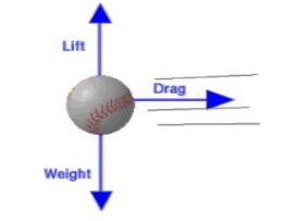
Figure: Diagrammatical representation of drag force, lift and weight.
The resultant of shear & pressure forces acting in the direction of flow, is called Drag Force.
Drag is the retarding force exerted on a moving body in a fluid medium.
It does not attempt to turn the object, simply to slow it down.
It is a function of the speed of the body, the size (and shape) of the body, and the fluid through which it is moving.

Where  = Drag Coefficient
 Drag force
Q4) A vehicle travels with a speed of 80 km per h, with a drag coefficient of 0.25. If the cross-sectional area is 6 square meters, then find out the drag force.
A4) Velocity, V = 80 km per h = 80 × 5/18 m per sec
= 22.22 m per sec
Drag coefficient, Cd= 0.25
Cross-sectional area, A =6 m2
Density of fluid,  =1.2 kg/cm3
The drag force formula is:
D=(Cd× ×V2×A)/2
D=444.35 N
Q5) The drag coefficient of a car at the design conditions of 1 atm, 20°C and 95 km/h is to be determined experimentally in a large wind tunnel in a full-scale test (Fig 11-90. The frontal area of the car is 2.07  . If the force acting on the car in the flow direction is measured to be 300 N, determine the drad coefficient of this car.
A5)
The drag force acting on a car is measured in a wind tunnel. The drag coefficient of the car at test conditions is to be determined.
Assumptions:
1. The flow of air is steady and incompressible.
2. The cross section of the tunnel is large enough to simulate free flow over the car.
3. The bottom of the tunnel is also moving at the speed of air to approximate actual driving conditions or this effect is negligible.
Properties: The density of air 1 atm and 20°C is 𝛒 = 1.204 kg/m3
Analysis: The drag force acting on a body and the drag coefficient are given by
 and
and 
Where a is the frontal area. Substituting and noting that 1 m/s =3.6 km/h, the drag coefficient of the car is determined to be

Q6) What is circulation in fluid mechanics?
A6) The circulation, C, about a closed contour in a fluid is defined as the line integral evaluated along the contour of the component of the velocity vector that is locally tangent to the contour.
Circulation, which is a scalar integral quantity, is a macroscopic measure of rotation for a finite area of the fluid.
“Meaning” of Circulation:
Circulation can be considered as the amount of force that pushes along a closed boundary or path. Circulation is the total “push” you get when going along a path, such as a circle.
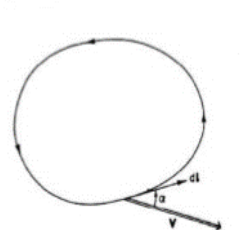
Figure: Circulation


Q7) Elaborate about the lift force in detail.
A7) The force per unit length of cylinder due to pressure on the cylinder surface can be obtained by integrating the surface pressure around the cylinder.
The tangential velocity along the cylinder surface is obtained by letting r=

The surface pressure as obtained from Bernoulli equation is

Where is the pressure at far away from the cylinder.
Hence,

The force due to pressure in x and y directions are then obtained by-

Where 

The development of the lift on rotating bodies is called the Magnus effect. It is clear that the lift force is due to the development of circulation around the body.
An airfoil without rotation can develop a circulation around the airfoil when Kutta- condition is satisfied at the rear tip of the air foil.
Therefore, the tangential velocity along the cylinder surface is obtained by letting r=
This forms the base of aerodynamic theory of airplane.
Q8) Water is flowing over a thin smooth plate of length 4 m and width 2 m at a velocity of 1 m/s. If the boundary layer flow changes from laminar to turbulent at a Reynold number  Find (i) the distance from leading edge upto which boundary layer is laminar, (ii) the thickness of the boundary layer the transition point, and (iii) the drag force on one side of the plate. Take viscosity of water μ=9.81×10⁻⁴ Ns/m2.
A8) Given:
Length of plate, 
Width of plate, 
Velocity of flow, 
Reynold number for laminar boundary layer = 5× 
Viscosity of water, 
(i) Let the distance from leading edge upto which laminar boundary layer exists =

∴
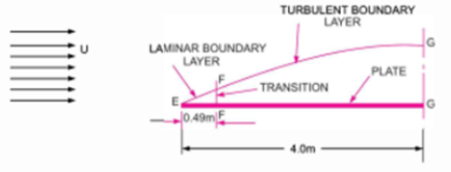
(ii) Thickness of boundary layer at the point where the boundary layer changes from laminar turbulent i.e., at Reynold number= , is given by Blasius’s solution as
 Here
Here 


(iii) Drag force on the plate on one side=Drag due to laminar boundary layer + Drag due to turbulent boundary.
a) Drag due to laminar boundary layer (i.e., from E to F)

Where  is given by Blasius solution for laminar boundary layer as
 where for EF,

A = Area of plate up to laminar boundary layer

Substituting the value of  and A in equation (i) we get

(b) Drag force due to turbulent boundary layer from F to G =
Drag force due to turbulent boundary layer form E to G – Drag force due to turbulent flow from E to F


Where  Area of plate upto EF =EF×b=0.49×2=0.98 m2 and


Drag force due to turbulent boundary layer from F to G = 

Drag force on the plate on one side = Drag force due to laminar boundary layer up to F +Drag due to turbulent boundary layer form F to G

Q9) Oil with a free-stream velocity of 2 m/s flows over a thin plate 2m wide and 2m long. Calculate the boundary layer thickness and the shear stress at the trailing end point and determine the total surface resistance of the plate. Take specific gravity as 0.86 and kinematic viscosity as 
A9) Given:
Free stream velocity of oil, U=2 m/s
Width of plate, b=2 m
Length of plate, L=2 m
 Area of plate, A=b×L=2×2=4
Specific gravity of oil, S=0.86
 Density of oil, =0.86×1000=860kg/
Kinematic viscosity, v = 
Now the Reynold number at the trailing end,

Since  is less than
 , the boundary layer is laminar oer the entire length of the plate.
Thickness of boundary layer at the end of the plate from Blasius’s solution is,

Shear stress at the end of the plate is 
Surface resistance on one side of the plate is given by

Where 

Total Resistance 
Q10) Derive an expression for drag and lift.
A10)
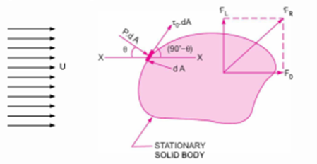
Figure. Stationary solid body
Consider an arbitrary shaped solid body placed in a real fluid, which is flowing with a uniform velocity U in a horizontal direction as shown in Fig 14.2 Consider a small elemental area  on the surface of the body. The forces acting on the surface area
  are.
are.
1. Present force equal to p× , acting perpendicular to the surface and
2. Shear force equal to  acting along the tangential direction to the surface.
Let θ= Angle made by pressure force with horizontal direction.
(a) Drag force ( The drug force on elemental area = Force due to pressure in the direction of fluid motion + Force due to shear stress in the direction of fluid motion=
Total drag, 

The term  is called the pressure drag or form drag while the term
  is called the friction drag or skin drag or shear drag.
(b) Lift Force (


Negative sign is taken with pressure force as it is acting in the down ward direction while shear force is acting vertically up.
 Total lift,

The drag and lift for a body moving in a fluid of density , at a uniform velocity u are calculated mathematically as


Where  Co-efficient of drag,
 Co-efficient of lift,
 Area of the body which is the projected area of the body perpendicular to the direction of flow
Or
= Largest projected area of the immersed body
The resultant force on the body.

The equation (3) and (4) which give the mathematical expression for drag and lift are derived by the method of dimensional analysis.
Q11) Three water tanks A, B and C with water surface levels (100.00), (50.00) and (10.00) m are connected by pipes AJ, BJ and CJ to a common joint J of a level (45.00) m. The three pipes have the same length, diameter and friction coefficient. a) Calculate the head at the joint J? b) Determine the discharge in each pipe?
A11) Assume, QAJ = QJB + QJC
Applying Bernoulli’s equation between A and J:
HA = HJ + hf AJ
100 + 0 + 0 = HJ + hf AJ
100 - HJ = hf AJ = K Q 2AJ
Where, K = 32 f l / 2 g d5
Q AJ = (100 - H J )1/2 / (K) ½ …………………….(1)
Similarly, applying Bernoulli’s equation between J and B:
HJ = HB + hf JB
HJ - 50 = hf JB = K Q2 JB
QJB = (HJ - 50) 1/2 / (K) 1/2 .............. (2)
Also, applying Bernoulli’s equation between J and C:
HJ = HC + hf JC
HJ - 10 = hf JC = K Q2 JC
QJC = (HJ - 10)1/2/ (K)1/2……………………………..(3)
Solving equations 1, 2 and 3 by trial and error, we get:
Assumed HJ | QAJ x (K)1/2 | JB x (K)1/2 | QJC x (K) | (QJB+QJC)x(K)1/2 |
70 60 53 51 50.5 50.45 50.4 50
| 5.48 6.325 6.855 7 7.036 7.039 7.043 7.071 | 4.47 3.162 1.732 1 0.707 0.671 0.632 0 | 7.745 7.07 6.557 6.4 6.364 6.36 6.356 6.324 | 112.216 10.233 8.389 7.4 7.07 7.031 6.988 6.324 |
From the table:
HJ = 50.45 m
QAJ = 7.039 / (K)1/2
QJB = 0.671 / (K)1/2
QJC = 6.36 / (K)1/2
It has to be noted that if HJ < 50, then the flow will be from B to J.
Q12) Two tanks A and B have 70 m difference in water levels, and are connected by a pipe 0.25 m diameter and 6 km long with 0.002 friction coefficient. The pipe is tapped at its mid point to leak out 0.04 m3 /s flow rate. Minor losses are ignored. Determine the discharge leaving tank A? Find the discharge entering tank B?
A12) hf = hf1 + hf2
70 = hf1 + hf2
70 = k1 Q12 + k2 Q22
k1 = k2 = 32 f L /2 g d2
= 32 X0.002 X 3000 / 2 X 9.81X 0.255
= 2032.7
70 = k1 Q12 + k1 Q22
Q1 = Q2 + Q3
= Q2 + 0.04
70 = k1 (Q2 + 0.04)2 + k1 Q22
= k1 (Q22+ 0.08 Q2 + 0.0016) + k1 Q22
= k1 Q22 + 0.08 k1 Q2 + 0.001
= 2 k1 Q22 + 0.08 k1 Q2 + 0.0016 k1
= 4065.4 Q2 2 + 162.6 Q2 + 3.25 0.0172
= Q22 + 0.04 Q2 + 0.0008 Q22 + 0.04 Q2 – 0.0164 = 0

Q2 = 0.11 m3 /s & Q1 = 0.15 m3 /s
Q13) A tank transmits 100 L/s of water to the point C where the pressure is maintained at 1.5 kg/cm2 . The first part AB of the pipe line is 50 cm diameter and 2.5 km long, and the second part BC is 25 cm diameter and 1.5 km long. The friction coefficient is 0.005 and minor losses are ignored. Assuming level at C is (0.0); find the water level (L) in the tank?
A13) hC = PC / ᵧ
= 1500 / 1
= 1500 cm = 15 m
HC = 15 = L – hfAB - hfBC
hfAB = 32 f1 L1/2 g d15
= 32 X 0.005X 2500 /2X 9.81X 0.55 = 1.32
HfBC = 32 f2 L2/2 g d25
= 32X0.005X1500//2X 9.81X 0.255 =25.38
15 = L – 1.32 – 25.38
L = 41.7 m
Q14) Two reservoirs have 6 m difference in water levels, and are connected by a pipe 60 cm diameter and 3000 m long. Then, the pipe branches into two pipes each 30 cm diameter and 1500 m long. The friction coefficient is 0.01. Neglecting minor losses, determine the flow rates in the pipe system?
A14) hf = hf1 + hf2
6 = hf1 + hf2
6 = k1 Q12 + k2 Q2 2
K1 = 32 f1 L1/2 g d15 = (32 x0.01 x 3000) /(2 x9.8x0.65 ) =127.64
K2 = 32 f2 L2/2 g d25 = (32 x0.01 x 1500) /(2 x9.8x0.35 ) =4084.48
k2 = 32 k1
6 = k1 Q12 + 32 k1 Q22
Hf2 = hf3 & k2 = k3 Q2 = Q3
Q1 = Q2 + Q3 = 2 Q2
6 = k1 Q12 + 8 k1 Q12 = 9 k1 Q12 = (9 x 127.64) Q1 2 = 1148.76Q12
Q1 = 0.072 m3 /s
& Q2 = 0.036 m3 /s
Q15) Two pipes are connected in parallel between two reservoirs that have difference in levels of 3.5 m. The length, the diameter, and friction factor (4 f) are 2400 m, 1.2 m, and 0.026 for the first pipe and 2400 m, 1 m, and 0.019 for the second pipe. Calculate the total discharge between the two reservoirs
A15) HL = 32 f1 L1/2 g d15 = 32 f2 L2/2 g d25
3.5 = 32 f1 L1/2 g d25 =8x0.026x2400xQ12 /2 9.81 X(1.25)5
Q1 = 1.29 m3/sec
3.5 = 32 f1 L1/2 g d25 = 8x0.019x2400xQ22 /2x9.81 x1 5
Q2 = 0.96 m3/sec
Q = Q1 + Q2
= 1.29 + 0.96
Q = 2.25 m3/sec
Q16) A pipe, 40 m long, is connected to a water tank at one end and flows freely in atmosphere at the other end. The diameter of pipe is 15 cm for first 25 m from the tank, and then the diameter is suddenly enlarged to 30 cm. Height of water in the tank is 8 m above the centre of pipe. Darcy’s coefficient is 0.01. Determine the discharge neglecting minor losses?
A16) Loss due to friction,
HLf = hf1 + hf2
HF = 32 f L/2 g d5 , f = 0.01 Total losses,
hT = Q2 [ ( 32 f L1/2 gd15 ) + 32 f L2 / 2 gd25
8 = Q2 ( (32x0.01) x (25)/ 2g (0.15)5+ (32x0.01) (15)/ 2 g (0.3)5 )
Q = 0.087 m3/sec
Q17) A pipe transmits water from a tank A to point C that is lower than water level in the tank by 4 m. The pipe is 100 mm diameter and 15 m long. The highest point on the pipe B is 1.5 m above water level in the tank and 5 m long from the tank. The friction factor (4 f) is 0.08, with sharp inlet and outlet to the pipe. a. Determine the velocity of water leaving the pipe at C? b. Calculate the pressure in the pipe at the point B.
A17) Applying Bernoulli’s equation between A and C,
Head loss due to entry (tank exit, from table) = 0.5 (v2 C/2g)
Head loss due to exit into air without contraction = 0
ZA + 0 + 0 = ZC + 0 + (v2 C/2g) + 0.5 (v2 C/2g) + 0 + 4fLV2c/2gd
4 = (v2 C/2g) x {1 + 0.5 + (4x0.08x15)/0.1}
Vc = 1.26 m/s
(b) Applying Bernoulli’s equation between A and B,
ZA + 0 + 0 = ZB + PB/ρg + (v2 B/2g) + 0.5 (v2 B/2g) + 4fLV2/2gd
- 1.5 = PB/(1000x9.81) + (1.262 /2x9.81) X {1 + 0.5 + (4x0.08x5)/0.1}
PB = - 28.61 kN/m2