Unit-2
Instrumentation system element
Q1) Write a note on performance terminology of instrumentation system.
A1) Range
Range is the region between upper and lower limit within which instrument is design to operate for measuring, indicating, recording a physical quantity. For example, a thermometer has a scale from −40°C to 100°C. Thus the range varies from −40°C to 100°C.
Span
Span is algebraic difference of upper and lower limit. For example, a thermometer, its scale goes from −40°C to 100°C. Thus its span is 140°C.
Error
Error is defined as the difference between the result of the measurement and the true value of the quantity being measured. For example displacement sensor shows displacement of 29.8 mm, but the actual displacement is 30 mm, therefore the error is - 0.2 mm.
Accuracy
Accuracy is closeness with which instrument reading approaches true value of variable under measurement. If the difference between reading and true value is very less then instrument it is said to be having high accuracy i.e. accuracy refers to how closely the measured value is close to its corresponding true value. It is often expressed as a percentage of the full range output or full–scale deflection. A piezoelectric transducer used to measure dynamic pressure is capable to detect pressures between 0.1 and 10,000 psig (0.7 KPa to 70 MPa). If it is specified with the accuracy of about±1% full scale, then the reading given can be expected to be within ± 0.7 MPa.
Sensitivity The ratio of change in output to the change in input of the instrument is known as sensitivity of instrument. For example, consider a voltmeter in which the input voltage  changes by 2 V, then the output reading should also change by 2 V. Therefore, the sensitivity is expressed as
  thus it represent how instrument respond to change in input.
Nonlinearity
| |
|
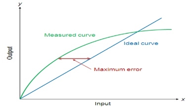
Maximum deviation of the actual measured curve of a sensor from the ideal curve is known as non-linearity error. Figure 1show graph between measured value and ideal values. Linearity is often specified in terms of percentage of nonlinearity, which is defined as:
Nonlinearity (%) = Maximum deviation in input ⁄ Maximum full scale input |
|
The static nonlinearity depend on environmental factors, including temperature, vibration, acoustic noise level, and humidity. Therefore it is important to know under what conditions the specification is valid.
Hysteresis
| |
|
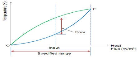
The hysteresis is an error of a sensor, which is defined as the maximum difference in output at any measurement value within the sensor's specified range when approaching the point first with increasing and then with decreasing the input parameter. Figure 2.1.2 shows the hysteresis error might have occurred during measurement of temperature using a thermocouple. The hysteresis error value is normally specified as a positive or negative percentage of the specified input range.
Resolution
Resolution is the smallest detectable incremental change of input parameter that can be detected in the output signal. Resolution can be expressed either as a proportion of the full-scale reading or in absolute terms. For example, if a LVDT sensor measures a displacement up to 20 mm or it provides an output as a number between 1 and 100 then the resolution of the sensor device is 0.2 mm.
Stability
Stability is the ability of a sensor device to give same output when used to measure a constant input over a period of time. The term ‘drift’ is used to indicate the change in output that occurs over a period of time. It is expressed as the percentage of full range output.
Dead band/time
The dead band or dead space of a transducer is the range of input values for which there is no output. The dead time of a sensor device is the time duration from the application of an input until the output begins to respond or change.
Repeatability
It specifies the ability of a sensor to give same output for repeated applications of same input value. It is usually expressed as a percentage of the full range output:
Repeatability = (maximum – minimum values given) X 100/full range |
|
Response time
Response time describes the speed of change in the output on a step-wise change of the measurand. It is always specified with an indication of input step and the output range for which the response time is defined.
Q2) Explain Potentiometer sensor.
A2) Potentiometer sensor:
Potentiometer sensor consists of resistance element, sliding contact which moves over a length of element. Displacement is converted into potential difference. For rotary potentiometer rotatable sliding contact rotate over circular wire wound track or conductive plastic film as shown in figure 3. Input voltage  is supplied between terminal 1 and 3. Output voltage
  is measured between terminal 2 and 3.
  . Output is proportional to angle through which slider is rotated when wire wound track have constant resistance per unit length i.e. per unit angle. When slider moving from one turn to other causing voltage change in steps. Each step is being a movement of one turn. Resolution as percentage is 100/N for N turn of potentiometer. Thus resolution of wire track depends upon diameter of wire. For coarsely wound track diameter is about 0.15mm and 0.5mm for finely wound track. Load
  is connected across output and potential difference across load
  is directly proportional to
  if load resistance is infinite. For finite load, effect of load is to transform linear relationship between output voltage and angle into a non-linear relationship.
  is parallel with fraction x of the potentiometer resistance
  therefor combine resistance is
|
|
Voltage across load is fraction that resistance across the load is of total resistance across which the applied voltage is connected.
If the load is of infinite resistance then
|
Potentiometers are used as sensors in machine-tool controls, elevators, liquid-level assemblies, forklift trucks, automobile throttle controls. In manufacturing, potentiometers are used for control of injection moulding machines, woodworking machinery, printing, spraying, robotics, etc. These are also used in computer-controlled monitoring of sports equipment.
Q3) Explain Strain gauge.
A3) Strain gauge-
Electrical resistive type strain gauges are consists of metal wire or metal foil strip or semiconductor material strip which so thin like wafer and can be stuck onto surfaces as shown in figure 4. These strips are made of Constantan alloy (copper-nickel 55-45% alloy) and are bonded to a backing material plastic (ployimide), epoxy or glass fiber reinforced epoxy. The strain gauges are stuck to the work piece by using epoxy or Cyanoacrylate cement Eastman 910 SL. The strain in an element is a ratio of change in length in the direction of applied load to the original length of an element. Principle behind strain gauge is fractional change is resistance is proportional to strain.
|
where G, the constant of proportionality and called the gauge factor.
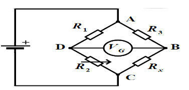
Due to external loading; work piece undergoes change in its shape the resistance of strain gauge element changes. This change in resistance is detected by Wheatstone’s resistance bridge as shown in figure 5. Wheatstone’s resistance bridge balance equation is given by
|
where Rx is resistance of strain gauge element, R2 is balancing/adjustable resistor, R1 and R3 are known constant value resistors. The measured deformation by the stain gauge is calibrated against change in resistance of adjustable resistor R2 which makes the voltage across nodes A and B equal to zero.
|
The gauge factor G is generally taken about 2.0-4.0 and resistances are generally taken about 100 Ω.
|
Strain gauges are widely used in experimental stress analysis and diagnosis on machines and failure analysis. They are basically used for multi-axial stress fatigue testing, proof testing, residual stress and vibration measurement, torque measurement, bending and deflection measurement, compression and tension measurement and strain measurement.
Strain gauges are primarily used as sensors for machine tools and safety in automotives. In particular. Strain gauges are also employed for force measurement in machine tools, hydraulic or pneumatic press and as impact sensors in aerospace vehicles.
Q4) Explain Linear variable differential transformer (LVDT).
A4) Alternating electro-magnetic forces (emfs) are generated in secondary coil because of alternating voltage input to primary coil. If core is displaced towards secondary coil 1 than in secondary coil 2, then more emf is generated in secondary one coil and there is a resultant voltage from the coils. As magnetic core is moves further value of resultant voltage increases in proportion with the displacement. With the help low pass filters and demodulators, precise displacement can be measured by using LVDT sensors. LVDT have good repeatability and reproducibility and high reliable.
Applications of LVDT
Q5) Explain.
A5) Eddy current proximity sensor
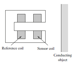
This sensors are used to detect non-magnetic but conductive materials. When an alternating current is passed thru this coil, an alternative magnetic field is generated. If a metal object comes in the close proximity of the coil, then eddy currents are induced in the object due to the magnetic field. These eddy currents create their own magnetic field which distorts the magnetic field responsible for their generation. As a result, impedance of the coil changes and so the amplitude of alternating current. This can be used to trigger a switch at some pre-determined level of change in current. Eddy current sensors are relatively inexpensive, available in small in size, highly reliable and have high sensitivity for small displacements. Figure 10 shows basic form of eddy current proximity sensors.
|
Applications of eddy current proximity sensors
Inductive proximity switch
|
This sensors are used to detect metals espeacilly ferrous metals.
It consists of four components coil, oscillator, detection circuit and output circuit. An alternating current is supplied to the coil which generates a magnetic field. When,a metal object comes closer to the end of the coil, inductance of the coil changes. This is continuously monitored by a circuit which triggers a switch when a preset value of inductance change is occurred.
Applications of inductive proximity switches
Q6) Explain Strain Gauge as force Sensor
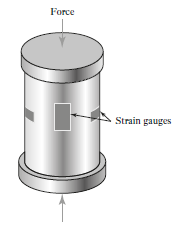
A6) Working of strain gauges are based on principle of change in electrical resistance. When element is subjected to load casuses tension or compression depending on load direction this causes change in resistance of material. Figure 16 shows strain gauge load cell. It consists of cylindrical tube to which strain gauges are attached. A load applied on the top collar of the cylinder compress the strain gauge element which changes its electrical resistance. Generally strain gauges are used to measure forces up to 10 MN.
|
Q7) Write a short note on Fluid pressure sensors.
A7) Fluid Pressure
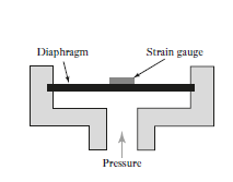
It necessary to measure pressure of system regularly for pertoleum, chemical, power industries. There are various types instruments such as diaphragms, capsules, and bellows are used to monitor the fluid pressure. Figure shows 17 specially designed strain gauges doped in diaphragms which is speacilly used in automobile to measure inlet manifold pressure.
|
Pressurized fluid displaces the diaphragm and this displacement is measured by strain gauge which placed above diaphragm.
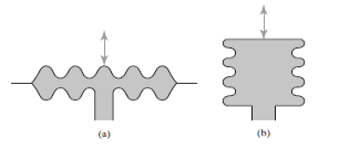
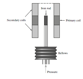
Capsules are formed by combining two corrugated diaphragm which increase the sensitivity as compare to diaphragm. A stack of capsules is called as Bellows. Bellows with a LVDT sensor measures the fluid pressure in terms of change in resultant voltage
|
|
The above figure shows schematic arrangement of LVDT with bellows which is used to measure Fluid pressure. The principle behind this sensor is change in pressure is measured interms of change in resultant voltage across secondary coil.
Q8) Explain Liquid flow sensors.
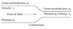
A8) Liquid flow measuremment is generally based on Bernoulli’s principle of fluid flow through constriction (figure 22). Quantity of fluid flow is measured by using pressure drop when fluid flows through constriction. For horizontal tube Bernoulli’s equation given as
|
where v1=fluid velocity p1= pressure A1=cross-sectional area of the tube prior to the constriction v2= the velocity p2= pressure A2=cross-sectional area at constriction, |
|
mass of liquid passing per second through the tube prior to the constriction must equal that passing through the tube at the constriction,
we have
|
Where
Q = quantity liquid passing through the tube per second
Orifice plate
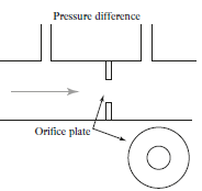
Orifice plate is simply as disc with hole at its center which is placed in the tube through which the fluid is flowing (Figure 23). The pressure difference is measured between a point equal to the diameter of the tube upstream and a point equal to the half the diameter downstream. Orifice plate is inexpensive and simple in construction with no moving parts. It exhibits nonlinear behavior and does not work with slurries. It has accuracy of ± 1.5%.
|
Turbine meter
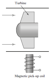
Turbine meter consists of multiblade rotor supported at center of pipeline through which flow is to be measured (Figure 24). As fluid flows through pipe so causing rotation of rotor. Angular velocity of is approximatly proportional to flow rate. A magnetic pick up coil is placed near the pipe which can determine rate of revolution of rotor. Turbine meter is expensive with accuracy of  .
.
|
Q9) Explain Bimetallic strips.
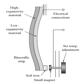
A9) It consists of two metal strips bonded together (Figure 26). These metals have different coefficients of expansion and when the temperature changes the composite strip bends into a curved strip, the higher coefficient metal is on the outside of the curve. This sensor can be used as controlling switch to control temperature rising above pre-set value. When the strips bend, the soft iron comes closer to magnet and further touches. Then the electric circuit completes and generates an alarm.
|
Q10) Explain: Temperature sensors.
A10) Resistance temperature detectors (RTDs)
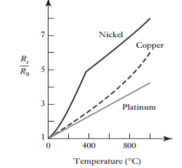
Electric resistance of a metal changes due to change in its temperature; this is the principle behind working RTDs. On heating up metals up to certain their resistance increases and follows a linear relationship as given below
Where Rt = Resistance at temperature T (°C) and R0 = Temperature at 0°C α = Temperature coefficient of resistance. The figure given below shows Variation of resistance with temperature for metals.
|
|
RTDs are simple resistive elements in the form of coils of wire of metals such as platinum, nickel or nickel–copper alloys; platinum is the most widely used due to its linear variation of resistance as temperature change thin-film platinum elements are often made by depositing the metal on a suitable substrate, wire-wound elements involving a platinum wire held by a high-temperature glass adhesive inside a ceramic tube (Figure 28). Such detectors are highly stable and give reproducible responses over long periods of time. They tend to have response times of the order of 0.5 to 5 s or more.
|
Applications of RTD
Thermistors
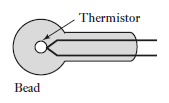
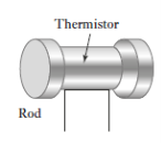
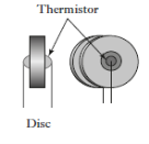
Thermistors are made from mixture of metal oxide such as those of chromium, cobalt, iron, manganese and nickel. These oxides are semiconductor. Materials are formed into various forms such as beads, discs and rods as shown in figure 29.
|
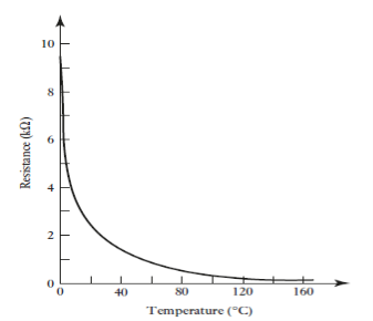
As temperature increases resistance of conventional metal-oxide thermistors decreases in non-linear manner (Figure 30). This is the principle behind working of Thermistors. And these Thermistors are known as negative temperature coefficient (NTCs). The resistance–temperature relationship can be describe mathematically as follows
Where
K and
|
Applications of Thermistors
|
Thermocouples
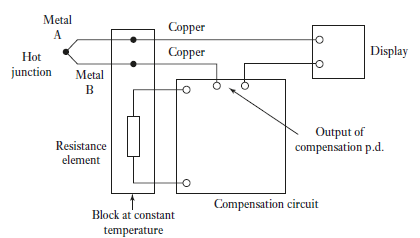
Thermocouple works on the fact that when a junction of dissimilar metals heated, it produces an electric potential related to temperature. As per Thomas Seebeck (1821), when two wires composed of dissimilar metals are joined at both ends and one of the ends is heated, then there is a continuous current which flows in the thermoelectric circuit. Figure 31 shows the schematic of thermocouple circuit. The net open circuit voltage (the Seebeck voltage) is a function of junction temperature and composition of two metals. It is given by,
ΔVAB = αΔT
Where α, the Seebeck coefficient, is the constant of proportionality.
|
Applications of Thermocouples
Q11) Explain Light sensors.
A11) Light sensors
Photoresistor
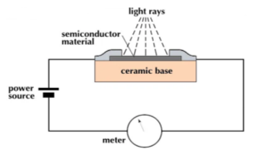
Photoresistor are also known as light dependant resistor (LDR). When incident light intensity is increases resistance of resistor in photoresistor decreases. This is working principle of photoresistor. It is made of a high resistance semiconductor material, cadmium sulfide (CdS). The resistance of a CdS photoresistor varies inversely to the amount of light incident upon it.Photoresistor follows the principle of photoconductivity which results from the generation of mobile carriers when photons are absorbed by the semiconductor material. Figure 32 shows basic construction of photoresistor.
|
The CdS resistor coil is mounted on a ceramic substrate. This assembly is encapsulated by a resin material. The sensitive coil electrodes are connected to the control system though lead wires. On incidence of high intensity light on the electrodes, the resistance of resistor coil decreases which will be used further to generate the appropriate signal by the microprocessor via lead wires.
Applications of photo resistor
Photodiodes
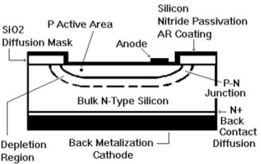
Photodiode is a solid-state device which converts incident light into an electric current. Photodiodes are semiconductor junction diodes connected into a circuit in reverse bias, so they give very high resistance. When there is no incident light, the reverse current is negligible and is termed the dark current. When light falls on the junction, extra hole–electron pairs are produced and there is an increase in the reverse current and the diode resistance drops. The reverse current is very nearly proportional to the intensity of the light. A photodiode can thus be used as a variable resistance device controlled by the light incident on it. Photodiodes have a very fast response to light.
|
It is constructed from single crystal silicon wafers. It is a p-n junction device. The upper layer is p layer. It is very thin and formed by thermal diffusion or ion implantation of doping material such as boron. Depletion region is narrow and is sandwiched between p layer and bulk n type layer of silicon. Light irradiates at front surface, anode, while the back surface is cathode. The incidence of light on anode generates a flow of electron across the p-n junction which is the measure of light intensity.
Applications of photo diodes
Safety Equipment
Automotive
Communications
