Unit – 1
Deformation in solids
Question 1: Describe the Elastic moduli and their relationships.
Answer:
Elastic moduli and the relationship between them
For all isotropic polymeric materials where Hook's law is valid, simple relationships exist between the elastic constants such as Young's modulus E, shear modulus G, bulk modulus B, and Poisson's ratio ν) As long as two of them are known, all others can be predicted. There are many different elastic constants from which we can choose. Often the relation between two moduli is expressed as a function of the Poisson ratio:


And for the Poisson’s ratio

From these relations it follows that −1 < ν < 1/2 are the classical bounds to the Poisson’s ratio. However, almost all classical materials lie within 1/5 < ν < 1/2.1 For isotropic weakly compressible materials such as liquids and rubbers, the Poisson's ratio approaches the upper bound ν = 1/2. In that case the elastic tensile modulus is three time the shear modulus and the bulk modulus is much larger than the Young's modulus,
E ≈ 3 G and B »E
The Poisson's ratio of rubber is never exact 0.5 because this means the elastic bulk modulus would go to infinity which is not possible. However, values very close to 1/2 have been reported (0.4999). In the case of quasi-isotropic polycrystalline polymers and other rather stiff isotropic polymers like polystyrene (polymers with bulky side groups), the Poisson's ratio reaches a value of about ν ≈ 1/3.
E ≈ 8/3 G and E ≈ B
For most engineering plastics, ν is in the range 0.35 < ν < 0.45 (see table of Poisson's ratios).
For a (hypothetical) material with no lateral contraction, ν = 0, the elastic tensile modulus is about two times the shear modulus and three times the bulk modulus:
E ≈ 2 G = 3 B
However, most common plastics have much larger Poisson's ratios, ν > 0.3.
Question 2: The state of plane stress at a point is represented by the stress element below. Determine the principal stresses and draw the corresponding stress element.
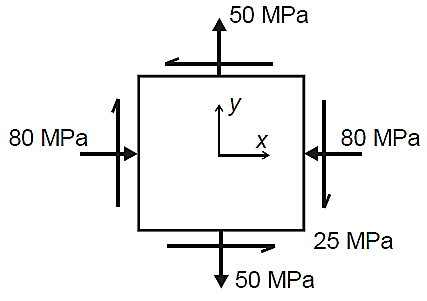
Answer:
Given:


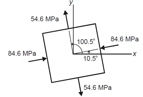
But we check we angle goes with which principal axis


Question 3: Define stress and its types.
Answer:

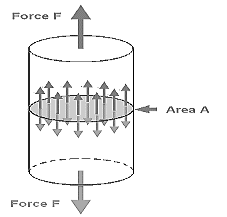
Types of Stress
Stress could be of the following types:
Question 4: Define:
Answer:
Tensile Stress:
The stress induced in a body, when subjected to two equal and opposite pulls as shown as a result of which there is an increase in length, is known as tensile stress. The ratio of increase in length to the original length is known as tensile strain. The tensile stress acts normal to the area and it pulls on the area.
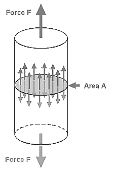
Fig. Tensile stress
Tensile stress Fig. 1.2 (a) shows a bar subjected to a tensile force P at its ends. Consider a section x-x, which divides the bar into two parts. The part left to the section x-x, will be in equilibrium if P = Resisting force (R). This is shown in Fig. 1.2 (b). Similarly, the part right to the section x-x, will be in equilibrium if P = Resisting force as shown in Fig. 1.2 (c). This resisting force per unit area is known as stress or intensity of stress.
∴Tensile stress

And tensile strain is given by,

Compressive Stress:
The stress induced in a body, when subjected to two equal and opposite pushes as shown in Fig. 1.3 (a) as a result of which there is a decrease in length of the body, is known as compressive stress. And the ratio of decrease in length to the original length is known as compressive strain. The compressive stress acts normal to the area and it pushes on the area. Let an axial push P is acting on a body in cross-sectional area A. Due to external push P, let the original length L of the body decreases by dL.
The compressive stress is given by-

The compressive strain is given by-


Shear Stress:
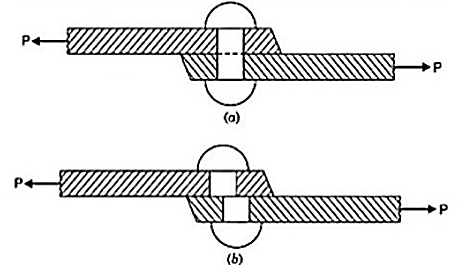
The stress induced in a body, when subjected to two equal and opposite forces which are acting tangentially across the resisting section as shown in Fig. 1.4 as a result of which the body tends to shear off across the section, is known as shear stress. The corresponding strain is known as shear strain. The shear stress is the stress which acts tangential to the area. It is represented by τ.
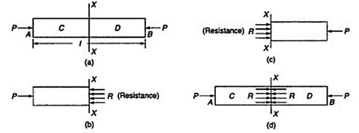
Fig. Shear stress
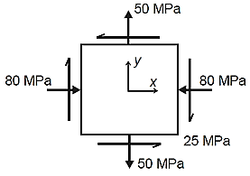
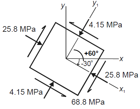
Question 5: The state of plane stress at a point is represented by the stress element below. Determine the stresses acting on an element oriented 30 degree clockwise with respect to the original element.
Answer:
Given:


Question 6: Define:
Answer:
Volumetric strain:
Volumetric strain of a deformed body is defined as the ratio of the change in volume of the body to the deformation to its original volume. If V is the original volume and dV the change in volume occurred due to the deformation, the volumetric strain ev induced is given by-
ev=dV/V


This means that volumetric strain of a deformed body is the sum of the linear strains in three mutually perpendicular directions.
Linear Strain:
It is defined as Linear strain may be either tensile or compressive. If there is some increase in the length of a body due to external force, then the strain is known as tensile strain.

On the other hand, if there is some decrease in the length of the body due to external force, then the strain is known as compressive strain. Please note that both are linear strain only. In the case of rod having uniform cross-section A. the normal stress ζ could be assumed to have a constant value P/A. Thus, it is appropriate to define ε as the ratio of the total deformation δL over the total length L of the rod. Whereas in the case of a member of variable cross-section, however, the normal stress ζ = P/A varies along the member, and it is necessary to define the strain at a given point as:

Shear Strain:
It is a measure of the angle through which a body is deformed by the applied force, denoted by γ. The shear strain is represented by the angle through which the other two faces have rotated as shown in Fig.

Question 7: Describe the Principal stresses and Principal plane.
Answer:
Principal stresses and principal plane
The magnitude of normal stress and shear stress may vary with respect to the inclination of planes. If we are concerned with the safety of solids under stress, we are required to find on which planes extreme values of normal and shear stress components are present. Hence, it is essential to know:
(a) Maximum tensile stress,
(b) Maximum compressive stress, and
(c) Maximum shear stress.
The extreme values of normal stresses are called the Principal Stresses and the planes on which the principal stresses act is called the principal planes.
In two-dimensional problems, there are two principal stresses, namely the major principal stress and the minor principal stress which are defined as the maximum and minimum values of the normal stresses respectively. Here, the maximum or minimum is to be considered algebraically.
For example, if the principal stresses happen to be 20 N/mm2 tensile and 75 N/mm2 compressive, the tensile stress of 20 N/mm2 is to be taken as the major principal stress denoted by the symbol σ1 and the compressive stress of 75 N/mm2 is to be taken as the minor principal stress (algebraically – 75 N/mm2) and denoted by the symbol σ2. The corresponding planes are defined as major and minor principal planes.
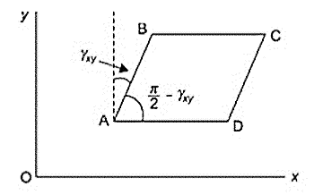
Fig: Principal Stress
Expressions of Principal Planes and Principal Stresses:
In calculus, you have learnt that when a function reaches maximum or minimum its derivative with respect to the independent variable becomes zero. Since the normal stress on an arbitrary plane is a function of the aspect angle θ as given by the expression,

Expression for major and minor principal stresses as follows

Above equations may be used to readily determine the principal planes and principal stresses.
Question 8: How much force is needed to pull a spring with a spring constant of 20 N/m a distance of 25 cm?
Answer:
The k of the spring is 20 N/m.
Δx is 25 cm.
We need this unit to match the unit in the spring constant, so convert the distance to meters.
Δx = 25 cm = 0.25 m
Plug these values into the Hooke’s Law formula. Since we’re looking for the force required to pull the spring apart, we don’t need the minus sign.
F = k·Δx
F = 20 N/m ⋅ 0.25 m
F = 5 N
A force of 5 Newtons is needed to pull this spring a distance of 25 cm.
Question 9: A spring is pulled to 10 cm and held in place with a force of 500 N. What is the spring constant of the spring?
Answer:
The change in position is 10 cm. Since the units on the spring constant are Newtons per meter, we need to change the distance to meters.
Δx = 10 cm = 0.10 m
F = k·Δx
Solve this for k by dividing both sides by Δx
F/Δx = k
Since the force is 500 N, we get
500 N / 0.10 m = k
k = 5000 N/m
The spring constant of this spring is 5000 N/m.
Question 10: A 2.0-m-long steel rod has a cross-sectional area of 0.30cm2. The rod is a part of a vertical support that holds a heavy 550-kg platform that hangs attached to the rod’s lower end. Ignoring the weight of the rod, what is the tensile stress in the rod and the elongation of the rod under the stress?
Answer:
Substituting numerical values into the equation gives us:


