Unit - 1
Design of Simple Machine Elements
Q1) Differentiate between Hardness, Toughness & Strength.
A1) The ability of a material to withstand friction, or abrasion resistance, is referred to as hardness.
The amount of force required for a material to deform is defined as its strength. The greater the force required to change the shape of a material, the more powerful it is.
How well the material resists fracture when subjected to force is known as Toughness. Toughness necessitates both strength and ductility, which allows a material to deform before fracturing.
Q2) Differentiate between Ductile & Brittle Materials.
A2)
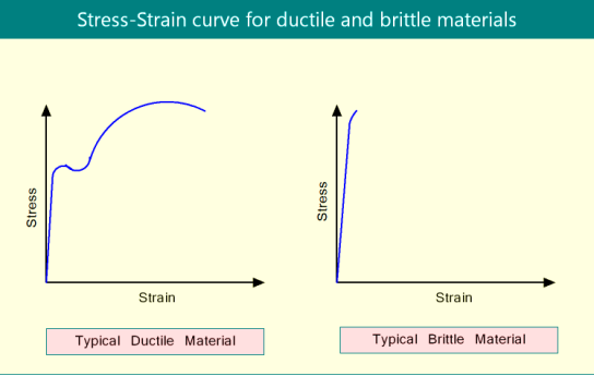
Ductile Materials:
- Ductile materials are solids that can undergo significant plastic deformation prior to fracture.
- Under tensile testing, the percentage elongation of ductile materials before fracture is greater.
- Under the action of external tensile loading, ductile materials fail gradually by neck formation.
- The energy absorbed by ductile materials prior to fracture during tensile testing is greater.
- When fatigue loading is applied to ductile materials, they have a longer life.
Brittle Material:
- Brittle materials are solids that exhibit negligible plastic deformation.
- Brittle materials have a very low percentage elongation before fracture in tensile testing.
- Brittle materials fail as a result of a sudden fracture (without any warning such as necking.
- Brittle materials absorb very little energy before breaking down.
- When fatigue loading is applied to brittle materials, they fail faster.
Q3) Differentiate between Yield strength & Ultimate strength.
A3) Yield Strength
- The maximum stress that a solid material can withstand when deformed within its elastic limit is defined as yield strength.
- Under tensile loading, it is the stress corresponding to the yield point (upper) in the engineering stress-strain curve.
- Brittle materials don't have a yield point. As a result, they lack yield strength.
- The yield strength of ductile materials is much lower than the ultimate strength.
- Yield strength is used when designing ductile material components or structures.
Ultimate Strength
- The ultimate strength of a solid material is defined as the maximum stress that it can withstand before failing.
- It is the stress in the engineering stress-strain curve that corresponds to the ultimate tensile strength (UTS) point under tensile loading.
- Ultimate strength is roughly 1.5 times greater than yield strength in ductile materials.
- Ultimate tensile strength is used when designing brittle material components or structures.
Q4) Define factor of safety & state different factors affecting it.
A4) It is defined, in general, as the ratio of the maximum stress to the working stress. Mathematically,

In case of ductile materials example mild steel, where the yield point is clearly defined the factor of safety is based upon the yield point stress. In such cases,

In case of brittle materials example cast iron, the yield point is not well defined as for ductile materials. Therefore, the factor of safety for brittle materials is based on ultimate stress.

This relation may also be used for ductile materials.
Selection of factor of safety
Before selecting a proper factor of safety, a design engineer should consider the following points:
- The reliability of the properties of the material and change of these properties during service.
- The reliability of test results and accuracy of application of these results to actual machine parts.
- The reliability of applied load
- The certainty as to exact mode of failure.
- The extent of simplifying assumptions.
- Extent of localised stresses.
- The extent of initial stresses set up during manufacture.
- The extent of loss of life is failure occurs; and
- The extent of loss of property failure occurs.
Q5) Define service factor.
A5)
- The service factor is defined as the minimum ratio between calculated capacity and average transmitted load for any component of the system.
For motors
- Service Factor is defined as a multiplier that is applied to the motor’s normal power rating to specify the load it can bear under nominal service conditions.
For gearbox
- The service factor is the ratio of the gearbox rated horsepower (or torque) to the application’s required horsepower (or torque)
Q6) Write down design procedure of spigot & socket cotter joint with neat sketch.
A6) The socket and spigot cotter joint is shown in figure
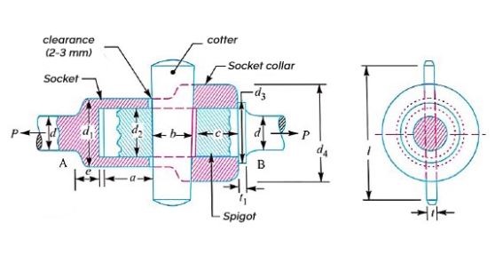
Let P=load carried by the rods
d=diameter of the rods,
 = outside diameter of socket,
 = diameter of spigot or inside diameter of socket,
 = outside diameter of Spigot collar,
 = thickness of spigot collar
 = diameter of socket collar,
c= thickness of socket collar,
b= mean width of cotter
t= thickness of cotter
l=length of cotter
a=distance from the end of the slot to the end of the rod,
 = Permissible tensile stress for the rod’s material,
 = Permissible shear stress for the cotter material, and
 = Permissible crushing stress for the cotton material.
Failure of the rods in tension
The roads may fail in tension due to the tensile load P. We know that
Area resisting tearing 
Tearing strength of the rods,

Equating this to load(P) we have

From this equation diameter of the rods (d) may be determined
Failure of Spigot in tension occurs the weaker section
Since the weakest section of the spigot is that section which has a slot in it for the cotter as shown in figure therefore
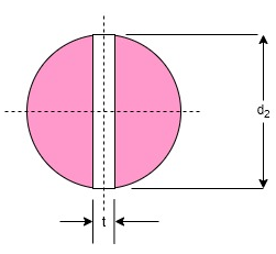
Area resisting tearing of the spigot across the slot

And tearing strength of the spigot across the slot

Equation this to load(P) we have

From this equation, the diameter of spigot or inside diameter of socket  may be determined
Assume the thickness of cotter is usually taken as 
Failure of the rod or cotter in crushing
We know that the area that resist crushing of a rod or cotter

Crushing strength=
Equating this to load (P) we have

From this equation, the induced crushing stress may be checked
Failure of the socket in tension across the slot
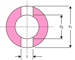
We know that the resisting area of the socket across the slot, as shown in figure

Tearing strength of the socket across the slot

Equating this to load (P) we have

From this equation, outside diameter of socket  may be determined
Failure of cotter in shear
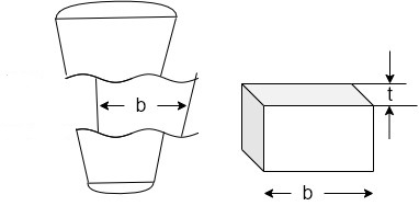
Considering the failure of cotter in share as shown in figure since the cotter is in double shear therefore shearing area of the cotter
=2 b×t
And shearing strength of the cotter

Equating these to load (P) we have

From this equation width of cotter b is determined
Failure of the socket collar in crushing
Considering the failure of socket collar in crushing as shown in figure
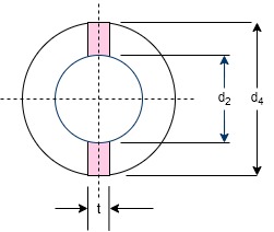
We know that area that resist crushing of socket collar

And crushing strength=
Equating this to load (P) we have
P=
From this equation, the diameter of socket  collar may be obtained
Failure of socket and in shearing
Since the socket end is in double shear, therefore area that resist shearing of socket collar

And shearing strength of socket collar

Equating this to load (P) we have

From this equation, thickness of socket collar c may be obtained
Failure of rod end in shear
Since the road end is in double share, therefore the area resisting shear of the road end

And shear strength of the rod end

Equating this to load (P) we have

From this equation the distance from the end of the slot to the end of the rod a may be obtained
Failure of Spigot collar in crushing
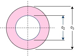
Considering the failure of the spigot collar in crushing as shown in figure we know that area that resist crushing of the collar

And crushing strength of the collar

Equating this to load (P) we have

From this equation, the diameter of the spigot collar  may be obtained
Failure of the spigot collar in shearing
Considering the failure of the spigot collar in shearing as shown in figure we know that area that resist sharing of the collar

And shearing strength of the collar,

Equating this to load (P) we have

From this equation, thickness of Spigot collar  may be obtained
Failure of cotter in bending
- In all the above relations, it is assumed that the load is uniformly distributed over the various cross sections of the joint.
- But in actual practice this does not happen and the cotter is subjected to bending.
- In order to find out the bending stress induced, it is assume that the load on the cotter in the rod end is uniformly distributed while in the socket and it varies from zero at the outer diameter and maximum at the inner diameter as shown in figure
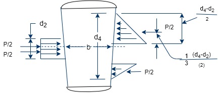
The maximum bending moment occurs at the centre of the quarter and is given by


Vinod that section modulus of the cotter,

Therefore bending stress induced in the cotter

This bending stress induced in the cotter should be less than the allowable bending stress of the cotter.
The length of cotter (l) is taken as 4d.
- The taper in cotter should not exceed 1 in 24.
- The draw of cotter is generally taken as 2 to 3mm.
Q7) Write down design procedure of knuckle joint with neat sketch.
A7)
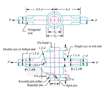
- The dimensions of various parts of the knuckle joint are fixed by empirical relations as given below.
If d is the diameter of rod, then diameter of pin,

Outer diameter of eye,

Diameter of knuckle pin head and collar

Thickness of single eye or rod end,

Thickness of fork, 
Thickness of pin head,
Other dimensions of the joint are shown in figure.
Failure of the solid rod in tension
Since the rods are subjected to direct tensile load, therefore tensile strength of the road,

Equating this to the load (P) acting on the rod, we have

From this equation, diameter of the rod (d) is obtained
Failure of the knuckle pin in shear
Since the pin is in double shear, therefore cross-sectional area of the pin under shearing

And the shear strength of the pin

Equating this to the load (P) acting on the rod, we have

From this equation, diameter of the knuckle pin  is obtained. This assumes that there is no slack and clearance between the pin and fork and hence there is no bending of the pin.
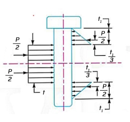
In case, the stress due to bending is taken into account, it is assumed that the load on the pin is uniformly distributed along the middle portion and varies uniformly over the forks as shown in figure.
Thus in the forks, a load  acts through a distance of
  from the inner edge and bending moment will be maximum at the centre of the pin. The value of maximum bending moment is taken by


And section modulus, 
Therefore, maximum bending tensile stress,
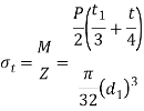
From this expression, the value of  may be obtained
Failure of the single eye or rod end in tension
The single eye on rod end may tear off due to the tensile load. We know that area resisting tearing

Tearing strength of single eye or rod end

Equating this to the load P we have

From this equation, The induced tensile stress ( for the single eye. In case the induced tensile stresses more than the allowable working stress, then increase the outer diameter of the eye
Failure of the single eye for rod end in shearing
The single eye rod end may fail in sharing due to tensile load. We know that area resisting sharing

Therefore, shearing strength of single eye

Equating this to the load P, we have

From this equation, the induced shear stress ( for the single eye or rod end may be checked.
Failure of the single eye on rod end in crushing
The single eye or pin may fail in crushing due to the tensile load. We know that area resisting crushing

Therefore, crushing strength of single eye or rod end

Equating this to the load P we have,

From this equation, the induced crushing stress ( for the single eye or pin maybe checked. In case induced crushing stress in more than the allowable working stress, then increase the thickness of the single eye (t).
Failure of the forked end in tension
The forked end or double eye may fail in tension due to the tensile load. We know that area resisting tearing

Therefore, tearing strength of the forked end

Equating this to the load P, we have

From this equation for the induced tensile stress for the forked end may be checked
Failure of the forked end in shear
The forked end may fail in shearing due to the tensile load. We know that area resisting shearing

Therefore, shearing strength of the forked end

Equating this to the load P, we have

From this equation, the induced shear stress for the forked end may checked. In case, the induced shear stress is more than the allowable working stress, then thickness of the fork  is increased.
Failure of the forked end in crushing
The forked end or pin me fail in crushing due to the tensile load. We know that area resisting crushing

Therefore, crushing strength of the forked end

Equating this to the load P we have

From this equation, the induced crushing stress for the forked end maybe checked.
Q8) Write down design procedure of hand lever with neat sketch.
A8) Hand lever with suitable dimensions and proportions is shown in figure.
Let, P = force applied at the handle
L = effective length of the lever
 = Permissible tensile stress and
 = Permissible shear stress
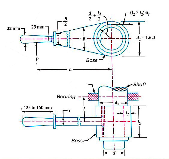
In designing hand levers, the following procedure may be followed
The diameter of the shaft (d) is obtained by considering the shaft under pure torsion. We know that twisting moment on the shaft

And resisting torque, 
From this relation, the diameter of the shaft (d) may be obtained.
The diameter of the boss  s taken as 1.6d and thickness of the boss
  as 0.3d.
The length of the boss  be taken from d to 1.25 d. It may be checked for a trial thickness
  by taking moments about the axis. Equating the twisting moment (P ×L) to the moment of resistance to tearing parallel to the axis, we get

The diameter of the shaft at the centre of the bearing  obtained by considering the shaft in combined bending and twisting.
We know that bending moment of the shaft,
M = P × l
And twisting moment, T = P × L
Therefore equivalent twisting moment

We also know that equivalent twisting moment,

The length l may be taken as 2
From the above expression, the value of  may be determined.
The key for the shaft is designed as usual for transmitting a torque of P × L.
The cross section of the lever near the boss may be determined by considering the lever in the bending.
Let, t = thickness of lever near the boss and
B = width or height of lever near the boss
We know that the bending moment on the lever,
M = P × L
Section modulus, Z = 
We know that the bending stress,

The width of the lever near the boss may be taken from four to five times the thickness of lever i.e., B =4t to 5t.
The width of the lever is tapered but the thickness (t) is kept constant. The width of the lever near the handle is 
Q9) Explain lever for safety valve.
A9)
- A Lever safety valve is shown in figure.
- It is used to maintain a constant safe pressure inside the boiler.
- When the pressure inside the boiler increases the safe value, the excess steam blows off through the valve automatically.
- The valve rests over the gunmetal seat which is secured to a casing fixed upon the boiler.
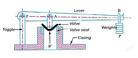
- One end of the liver is pivoted at the fulcrum F by a pin to the toggle, while the other and carries the weights.
- The valve is held on its seat against the upward steam pressure by the force P provided by the weights at B.
- The weights and its distance from the fulcrum are so adjusted that when the steam pressure acting upward on the valve exceeds the normal limit, it lifts the valve and the lever with its weights.
- The excess steam thus escapes until the pressure falls to the required limit.
- The lever maybe designs in the similar way as discussed earlier.
- The maximum steam load (W), at which the valve blows off, is given by

D = diameter of the valve and
P = steam pressure
Q10) Explain procedure to calculate stresses in the components subjected to eccentric loading.
A10)
- An external load, whose line of action is parallel but does not coincide with the centroidal axis of the machine component, is known as an eccentric load.
- The distance between the centroidal axis of the machine component and the eccentric load is called eccentricity and is generally denoted by e.
- The examples of eccentric loading, are c clamp, punching machines, brackets, offset connecting links etc.
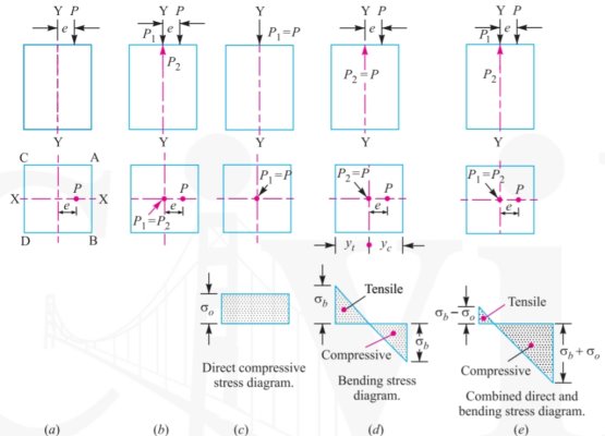
- Consider a short prismatic bar subjected to a compressive load P acting at an eccentricity of as shown in figure a
- Let us introduced two forces
 along the centre line or neutral axis equal in magnitude to P, without altering the equilibrium of the bar as shown in figure b.
 - The force
 will induce a direct compressive stress over the entire cross section of the bar, as shown in figure c
 - The magnitude of this direct compressive stress is given by
 where A is cross-sectional area of the bar.
- The force
 will form a couple equal to P×e which will cause bending stress.
 - This bending stress is compressive at the edge AB and tensile at edge CD, as shown in figure d.
- The magnitude of bending stress at the edge AB is given by
 compressive
And bending stress at the edge CD,
 tensile
Where,  = distance of the extreme fibres on the compressive and tensile sides, from the neutral axis respectively, and
I= second moment of area of the section about the neutral axis i.e., Y-axis
According to the principle of superposition, the maximum or the resultant compressive stress at the edge AB.

And the maximum or resultant tensile stress at the edge CD,

Q11) A tensioned rod with a cross-sectional area of A and an axial force of P = 2000 lbf experiences a stress of σ = P/A. Determine the diameter of a solid circular rod using a material strength of 24 kpsi and a design factor of 3.0.
A11)
Since A = πd2/4, σ = P/A
As,

(Or)


So,

Q12) Three rivets hold two plates together that have a tensile strength of 50 KN. The plates are made of plain carbon steel and have a tensile yield strength of 250N/mm2 Shear yield strength is 50% of tensile yield strength, with a factor of safety of 2.5. Then Determine the diameter of rivets and thickness of the plate neglecting stress concentration factors.
A12)

Syt = 250 N/mm2
Fos = 2.5
Permissible shear stress for rivets:

Diameter of rivets:
Since, there are3 rivets

Solving, we get d = 20.60 or 22 mm
Permissible tensile stress for plates:

Thickness of plates:


So, t= 3.73 or 4 mm
Q13) A colter joint must be designed to connect two steel rods of equal diameter. Each rod is subjected to a 50 kN (50 * 10^3 N) axial tensile force. Create the joint and specify its primary dimensions. Given:  . Rods, spigot end and socket end are assumed as 6, while for the cotter, it is taken as 4.
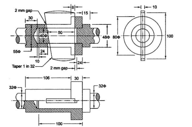
A13) Calculation of permissible stresses for rods, spigot, and socket


Calculation of permissible stresses for Cotter


Diameter of rods

Thickness of cotter

Diameter of spigot d1


Outside diameter  of socket


Diameter of spigot collar (d3) and socket Collar (d4)


a = c= 0.75d=24 mm
Width of collar (b)


Check crushing and shear stress in spigot


Check crushing and shear stress in socket


As, 
Thickness of spigot collar

Q14) A cotter joint is used to connect two rods. The inside diameter of the socket is 50 mm, and the outside diameter of the socket collar is 100 mm. A tensile force of 50 kN is applied to the rods. The cotter is made of steel 30C8 (Syt= 400 Nlmm2) and has a safety factor of 4. The cotter's width is five times its thickness. Calculate Width & Thickness of cotter on basis of shear failure and bending failure.
A14)
Permissible stresses for Cotter

Width and thickness based on shear failure
t = 10 mm
b = 5t = 50 mm
Width and thickness on basis of bending failure
d4 = 100 mm
d2 = 50 mm
t= 10.77 or 12 mm
b= 5t = 60 mm
(* NOTE: For Detailed Solution Refer Question 13)
Q15) It is necessary to design a knuckle joint to connect two circular rods subjected to an axial tensile force of 50 kN (50*10^3 N). The rods are co-axial, and a small amount of angular movement between their axes is allowed. Design the joint and specify the dimensions of its components. Choose appropriate materials for the components. Syt = 400 N/mm^2, Fos = 5. Assume Compressive strength is much higher than tensile strength.
A15)
Given
P=50*10^3 N
Syt = 400 N/mm^2
Fos = 5
Calculation of permissible stresses


Diameter of Rod

d = 28.21 or 30 mm
Enlarge diameter of rods (d1)
d1 = 1.1 d = 33 or 35 mm
Dimensions a & b
Thickness of fork
a = 0.75d=22.5 or 25 mm
Thickness of single eye or rod end
b = 1.25d=37.5 or 40 mm
Diameter of Pin

d = 28.2 mm
Also,

d = 40 mm
Outer diameter of eye 2d

Diameter of knuckle pin head and collar

Stresses in eye


Stresses in fork


So, Stress is within limits
Q16) Design cotter joint for a load varying from 30 KN inn compression to 30 Kn in tension. Tensile stress = compressive stress = 50 MPa; shear stress = 35 MPa and crushing stress = 90 MPa.
A16)
1. Diameter of the rods
Let d=diameter of the rods
Considering the failure of the rod in tension. We know that load (P)


2. Diameter of spigot and thickness of cotter
Let us now check the induced crushing stress in the rod or cotter. We know that load (P)


Since this value of  is more than the given value of
  , therefore the dimensions
  are not safe. Now let us find the values of
  and
and  by substituting the valure of
  in the above expression, i.e.

Let  Diameter of spigot or insider diameter of socket, and
 Thickness of cotter. It may be taken as
Considering the failure of the spigot in tension across the weakest section. We know that load (P)

 and thickness of cotter
  are not safe. Now let us find the values of
  and t by substituting the value of
  in the above expression


And 
 Outside Diameter of socket
Let 
Considering the failure of socket in tension at cotter. We know that load (P)


(Taking +ve sign)
4. Width of cotter
Let b= Width of cotter
Considering the failure of cotter in shear. Since the cotter is in double shear, therefore load (P)


5. Diameter of the socket collar
Let  Diameter of the socket collar
Considering the failure of the socket collar and cotter in crushing. We know that the load (P)


6. Thickness of socket collar
Let c=Thickness of socket collar
Considering the failure of the socket end in shear. Since the socket end is in double shear, therefore load (P)


7. Distance from the end of the slot to the end of the rod
Let  Distance from the end of the slot to the end of the rod
Considering the failure of the rod end in shear. Since the rod end is in double shear, therefore load (P)


8. Diameter of spigot collar
Let  = Diameter of spigot collar
Considering the failure of spigot collar in crushing. We know that load (P)


9. Thickness of spigot collar
Let 
Considering the failure of spigot collar in shearing. We know that load (P)


10. The length of cotter(l) is taken as 4d

11. The dimension e is taken as 1.2 d

Q17) Design a sleeve and cotter joint to resist a tensile load of 60 kN. All parts of the joint are made of the same material with the following allowable stresses:

A17)
Given: P = 60 kN = 60 × 103 N; σt = 60 MPa = 60 N/mm2 ; τ = 70 MPa = 70 N/mm2 ; = 125 MPa = 125 N/mm2
1. Diameter of the rods
Let  Diameter of the rods.
Considering the failure of the rod in tension. We know that load (P)


 or
or  36 mm
36 mm
2.Diameter of enlarged end of rod and thickness of cotter
Let  Diameter of enlarged end of rod, and t= Thickness of cotter. It may be taken as
Considering the failure of the rod in tension across the weakest section (i.e slot). We know that load (P)


 and thickness of cotter

Let us now check the induced crushing stress in the rod or cotter. We know that load (P)


Since the induced crushing stress is less than the given value of 125 N/ , therefore the dimension
  and t are within safe limits.
3. Outside diameter of Sleeve
Let 
Considering the failure of sleeve in tension across the slot. We know that load (P)


4. Width of cotter
Let b=width of cotter
Considering the failure of cotter in shear. Since the cotter is in double shear, therefore load (P)


5. Distance of the road from the beginning to the cotter hole (insider the sleeve end)
Let a= Required distance
Considering the failure of the rod end in shear. Since the rod end is in double shear, therefore load(P).


6. Distance of the rod end form its end to the cotter hole
Let c=Required distance
Considering the failure of the sleeve end in shear. Since the sleeve end is in double shear therefore load (P)


Q18) The big end of a connecting rod, as shown in Fig, is subjected to a maximum load of 50 kN. The diameter of the circular part of the rod adjacent to the strap end is 75 mm. Design the joint, assuming permissible tensile stress for the material of the strap as 25 MPa and permissible shear stress for the material of cotter and gib as 20 MPa.
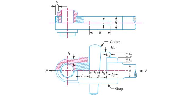
A18)
Given: P = 50 kN = 50 × 103 N; d = 75 mm ; σt = 25 MPa = 25 N/mm2 ; τ = 20 MPa = 20 N/mm2
1. Width of the strap
 Width of the strap
The width of the strap is generally made equal to the diameter of the adjacent end of the round part of the rod(d)


Thickness of gib
 and length of gib head
  Thickness of cotter=20mm
2. Thickness of the strap at the thinnest part
Let  Thickness of the strap at the thinnest part
Considering the failure of the strap in tension. We know that load (P)


3. Thickness of the strap at the cotter
Let  Thickness of the strap at the cotter
The thickness of the strap at the cotter is increased such that the area of the cross-section of the cotter hole is not less than the area of the strap at the tinnest part. In other words.

 or
or 

4.Total width of gib and cotter
Let B=Total width of gib and cotter
Considering the failure of gib and cotter in double shear. We know that load (P)

Since on gib is used, therefore width of giv,

And width of cotter, 
The other dimensions are fixed as follows:


Q19) Design a cotter joint to connect piston rod to the crosshead of a double acting steam engine. The diameter of the cylinder is 300 mm and the steam pressure is 1 N/mm2. The allowable stresses for the material of cotter and piston rod are as follows: 
A19)
Given: D = 300 mm; p = 1 N/mm2; σt = 50 MPa = 50 N/mm2; τ = 40 MPa = 40 N/mm2; σc = 84 MPa = 84 N/mm2
We know that maximum load on the piston rod

The various dimensions for the cotter joint are obtained by considering the different modes of failures as discussed below:
Let  Diameter of piston rod at cotter, and
 Thickness of cotter. It may be taken as 0.3
Considering the failure of piston rod in tension at cotter. We know that load (P)
We know that maximum load on the piston rod,

The various dimensions for the cotter joint are obtained by considering the different modes of failure as discussed below:
1. Diameter of piston rod at cotter
Let  Diameter of piston rod at cotter, and
 Thickness of cotter. It may be taken as 0.3
Considering the failure of piston rod in tension at cotter. We know that load (P)


And

2. Width of cotter
Let  width of cotter
Considering the failure of cotter in shear. Since the cotter is in double shear, therefore load (P)


 Diameter of socket
Let 
Considering the failure of socket in tension at cotter. We know that load (P)


 (Taking +ve sign)
Let us now check the induced crushing stress in the socket. We know that load (P).


Since the induce crushing is greater than the permissible value of 84  . Therefore let us find the value of
  by substituting
  in the above expression i.e.,

 mm
mm
We know the tapered length of the piston rod

Assuming the taper of the piston rod as 1 in 20 therefore the diameter of the parallel part of the piston rod,

And diameter of the piston rod at the tapered end

Q20) Design a knuckle joint for a tie rod of a circular section to sustain a maximum pull of 70 kN. The ultimate strength of the material of the rod against tearing is 420 MPa. The ultimate tensile and shearing strength of the pin material are 510 MPa and 396 MPa respectively. Determine the tie rod section and pin section. Take factor of safety = 6.
A20)
Given: P=70kN=70,000N;  for rod=420 MPa;
  for pin=510 MPa;
 ;
;
We know that the permissible tensile stress for the rod material.

And permissible shear stress for the pin material.

 Failure of the rod in tension
Let 


The other dimensions of the joint are fixed as given below.
Diameter of the knuckle pin

Outer diameter of the eye

Thickness of single eye or rod end,

Thickness of single eye or rod end.
Thickness of fork 
Now we shall check for the induced stresses as discussed below:
2. Failue of the knuckle pin in shear
Since the knuckle pin is in double shear, therefore load9P)


3. Failure of the singel eye or rod end in tension
The single eye or rod end may fail in tension due to the load. We know that load(P)/


4. Failure of the forked end in tension
The forked end may fail in tension due to the load. We know that load (P)

