Unit - 6
Mechanical Springs
Q1) What are the different types of springs?
A1)
1. Helical springs
- The helical springs are made up of a wire coiled in the form of a helix and is primarily intended for compressive or tensile loads.
- The cross section of the wire from the spring is made maybe circular, square or rectangular. The two forms of helical springs are compression helical spring as shown in figure (a) and tension helical spring as shown in figure (b).
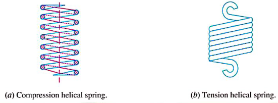
- The helical springs are said to be closely coiled when the spring wire is coiled so close that the plane containing each turn is nearly at right angles to the axis of the helix and the wire is subjected to torsion
- In an open coiled helical spring, the spring wire is coiled in such a way that there is a gap between the two consecutive turns as a result of which the helix angle is large.
2. Conical and volute springs
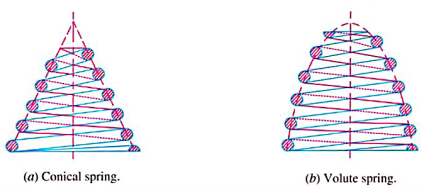
- The conical and volute springs, as shown in figure are used in special applications where a telescoping spring or a spring with a spring rate that increases with the load is desired.
- The conical spring, as shown in figure (a) is wound with a uniform pitch whereas the volute springs, as shown in figure (b) are wound in the form of paraboloid with constant pitch and lead angles.
3. Torsion springs
- These springs maybe of helical or spiral type as shown in figure.
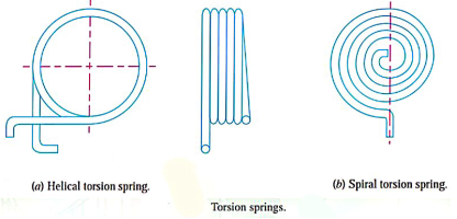
- The helical type may be used only in applications where the load tends to wind up the spring and are used in various electrical mechanism.
- The spiral type is also used where the load tends to increase the number of coils and when made of flat strip are used in watches and clocks.
4. Laminated or leaf springs
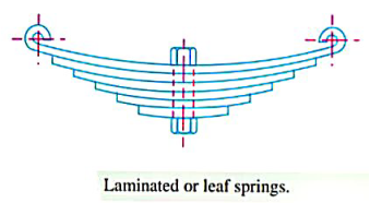
- The laminated or leaf spring consists of a number of flat place (known as leaves) of varying length held together by means of clamps and bolts, as shown in figure, these are mostly used in automobiles.
5. Disc or bellevile springs
- These springs consists of a number of conical disc held together against sleeping by a central bolt or tube as shown in figure.
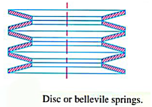
- These springs are used in applications where high spring rate and compact spring units are required.
6. Special purpose springs
- These springs are air or liquid springs, rubber springs, ring springs etc.
- The fluid (air or liquid) can behave as a compression spring.
- These springs are used for special types of application only.
Q2) State the different applications of spring.
A2)
Applications of spring
- To cushion, absorb or control energy due to either shock or vibration as in car springs, Railway buffers, aircraft landing gears, shock absorbers and vibration dampers.
- To apply forces, as in brakes, clutches and spring-loaded valves.
- To control motion by maintaining contact between two elements as in cams and followers.
- To measure forces, as in spring balances and engine indicators.
- To store energy, as in watches, toys etc.
Q3) What are the different materials used for springs?
A3)
- There are four basic varieties of Steel wire which are used in spring in the majority of applications:
- Patented and cold drawn Steel wires (unalloyed)
- Oil hardened and tempered spring Steel wires and valve spring wires.
- Oil hardened and tempered steel wires (alloyed) and
- Stainless Steel spring wires.
- The most extensively used spring material is high carbon hard drawn spring steel.
- It is often called 'patented and cold drawn' Steel wire. This operation produces a tough uniform structure that is suitable for severe cold drawing.
- The patented and cold drawn Steel wires are made of high carbon steel and contain 0.85 – 0.95 percent carbon.
- It has ability to withstand high stresses under repeated loadings.
- The patented and cold drawn Steel wires are the least expensive of all spring materials.
- The patented and cold drawn Steel wire are mainly used in springs subjected to static forces and moderate fluctuating forces.
- There are four grades of this wire, which are as follows:
Grade I: It is used in springs subjected to static or low load cycles.
Grade II: It is used in springs subjected to moderate load cycles.
Grade III: It is used in highly stressed static springs or springs subjected to moderate dynamic loads.
Grade IV: It is suitable for springs subjected to severe stresses.
- The second group of spring wires is unalloyed oil hardened and tempered spring Steel wires and valve spring wires.
- Oil hardened and tempered spring Steel wire contains 0.55 – 0.75% carbon.
- The wire is cold drawn and then hardened and tempered.
- Valve spring wire contains 0.60 – 0.75% carbon.
- It is the highest quality of oil hard and tempered Steel wire.
- It has excellent surface finish and considered to be most reliable for applications involving fluctuating forces.
- It is used for applications where the stresses are severe.
- There are two grades of unalloyed, oil hardened and tempered spring steel wire SW and VW.
- Grade SW is suitable for spring subjected to moderate fluctuating stresses, whereas grade VW is recommended when the spring is subjected to a high magnitude of fluctuating stresses.
- There are two popular varieties of alloy Steel wires, namely chromium vanadium Steel and chromium silicon Steel.
- Chromium vanadium Steel contains 0.48 -0.53 % carbon, 0.80 – 1.10 % chromium, and 0.15% vanadium.
- These wires are used for applications involving higher stresses and for spring subjected to impact for shock loads, such as in pneumatic hammer.
- Chromium silicon Steel contains 0.51 – 0.59 percent carbon, 0.60 – 0.80 percent chromium and 1.2 – 1.6% silicon. These wires are used for applications involving highly stressed springs subjected to shock for impact loading.
Q4) Derive stress & deflection equations for helical spring.
A4)
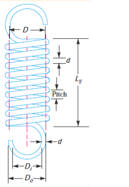
- Helical spring made from the wire of circular cross section is shown in figure (a).
- D and d are mean coil diameter and wire diameter respectively.
- The number of active coils in this spring is N. The spring is subjected to axial force P.
- When the wire of the helical spring is uncoiled and straightened it takes the shape of a bar as shown in figure(b).
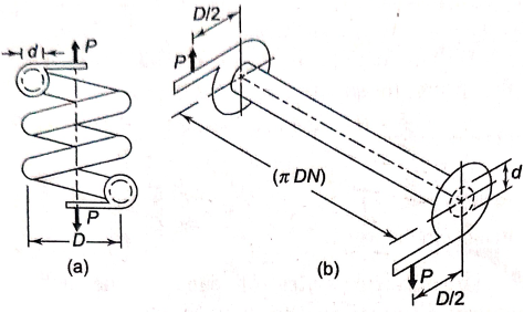
- In deriving stress equation, this is considered to be equivalent to the actual helical spring.
- The dimensions of equivalent bar are as follows
(i) The diameter of the bar is equal to the wire diameter of the spring (d).
(ii) The length of one coil in the spring is  There are N such active coils. Therefore, the length of equivalent bar is
(iii) The bar is fitted with bracket at each and. The length of this bracket is equal to mean coil radius of the spring (D/2).
- The force P acting at the end of the bracket induces torsional shear stress in the bar. The torsional moment M is given by

- The torsional shear stress in the bar is given by

- When the equivalent bar is bent in the form of helical coil, there are additional stresses on account of following two factors:
(i) There is a direct or transverse shear stress in the spring wire.
(ii) When the bar is bent in the form of coil, the length of the inside fibre is less than the length of the outside fibre. This result in stress concentration at the inside fibre of the coil.
- The resultant stress consists of superimposition of torsional shear stress, direct shear stress, and additional stresses due to the curvature of the coil.
- Equation (a) does not take into consideration the effect of direct shear stress and stress concentration due to curvature effect.
- It requires modification. We will assume following two factors to account for these effects.
 factor to account for direct shear stress
 fector to account for stress concentration due to curvature effect
- The combined effect of these two factors is given by

Where K is the factor to account for combined effect of two factors.
- As shown in figure (b) the direct shear stress in the bar is given by

- Superimposing the two stresses of expressions (a) and (b) the resultant shear stress in the spring wire is given by

- The shear stress correction factor
 is defined as
 (d)
(d)

Substituting above equation in expression (c)

- A.M Wahl equation is given by
 (10.6)
Where K is called stress factor or Wahl factor. The Wahl factor is given by

Where C is spring index
- Wahl factor provides simple method to find out resultant stresses in the spring.
- In normal applications, the spring is designed by using Wahl factor. When the spring is subjected to fluctuating stresses, two factors
 are separately used.
 - The angle of twist
 for the equivalent bar, illustrated in figure (b) is given by

Where.  =Angle of twist (radians)
 torsional moment (PD/2)
l= length of bar (
J = polar moment of inertia of bar 
G = modulus of rigidity
Substituting values in equation f

- As shown in figure and the deflection of the spring, for small values of is given by,

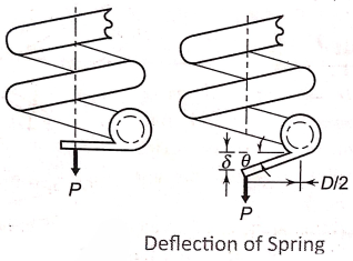
Substituting value of  from equation (g) in (h)

The above equation is called load deflection equation.
Q5) What are the different styles of ends?
A5)
- There are four common methods which are used in forming the ends of the helical compression spring plain ends, plane and ground ends, square ends and square and ground ends as shown in figure.
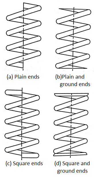
- The turns at the two ends do not affect the deflection calculated by the load deflection equation.
- Therefore, while calculating the number of active turns, the and turns should be subtracted from the total number of turns.
- The number of active terms for different styles of end is as follows
Types of ends | Number of active turns (N) |
Plain ends |  |
Plain ends (ground) |  |
Square ends |  |
Square ends (ground) |  |
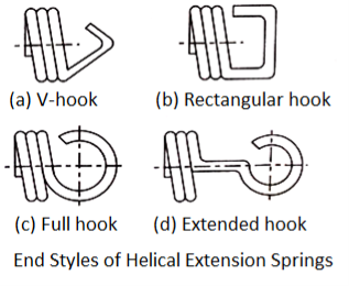
- The different styles of end for the helical extension spring as shown in figure.
- The end should be designed in such a way that the stress concentration at the bend is minimum.
- Sometimes, the effect of stress concentration in the end coils is so severe that the spring body becomes stronger than the end coils and failure occurs in the end coils.
- For helical extension springs, all coils are active coils. The number of active coils (N) is the same as the total number of coils

Q6) Write down design procedure of helical compression spring.
A6)
The basic procedure for the design of helical spring consists of following steps
(i) For the given application, estimate the maximum spring force (P) and the corresponding required deflection  of the spring. In some cases, maximum spring force and stiffness k, which is
  , are specified.
(ii) Select suitable spring material and find out ultimate tensile strength  from the data. Calculate the permissible shear stress for the spring wire by following relationship

(iii) Assume a suitable value for spring index (C). For industrial applications, the spring index varies from 8 to 10. A spring index of 8 is considered as a good value. The spring index for springs in valves and clutches is 5. The spring index should never be less than 3.
(iv) Calculate Wahl factor by following equation

(v) Determine wire diameter (d) by equation

(vi) Determine mean coil diameter (D) following relationship,
D=Cd
(vii) Determine the number of active coils (N), equation
The modulus of rigidity (G) for steel wires 81 370 

(viii) Decide the style of ends for the spring depending upon the configuration of the application. Determine the number of inactive coils. Adding active and inactive coils, find out the total number of coils 
(ix) Determine the solid length of the spring by following relationship
Solid length = 
(x)Determine the actual deflection of the spring by equation

(xi) Assume gap of 0.5 to 2 mm between adjacent coils, when the spring is under the action of maximum load. The total gap between coils is given by
Total gap=  gap between two adjacent coils
In some cases, the total axial gap is taken 15% of the maximum deflection.
(xii) Determine the free length of the spring by following relationship
Free length =solid length+ total gap + 
(xiii) Determine the pitch of the coil by following relationship
p = 
(xiv) Determine the rate of spring by equation

(xv) Prepare a list of spring specifications.
Q7) Explain spring in series & parallel.
A7)
- There are two types of springs connections - series and parallel.
- The objectives of series and parallel combinations are as follows:
- To save the space
- To change the rate of the spring at a certain deflection and
- To provide a fail safe system
Figure shows two springs, with spring rates  connected in series. For series connection,
- The force acting on each string is same and equal to the external force.
- The total deflection of spring combination is equal to the sum of the deflections of individual springs.

Therefore, 
Where  deflections of two springs.
We know

Substituting equation (b) in (a)

Where k is the combined stiffness of all springs in the connection.
The above expression can be written in the following form

Figure shows two springs, with spring rates  , connected in parallel. For parallel connection,
- The force acting on the spring combination is equal to the sum of forces acting on individual springs.
- The deflection of individual springs is same and equal to the deflection of the combination.
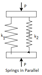
Therefore, 
We know

From equation c and d

Where k is the combined stiffness of all strings in the connection.
Q8) Explain concentric spring & derive stress equation for same.
A8)
- A concentric spring consists of two helical compression springs, one inside the other, having the same axis.
- It is shown in figure. Concentric spring is also called nested spring.
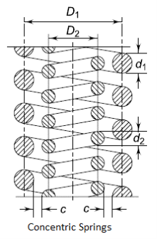
- In general, there are two springs. However, in certain applications, concentric springs consists of three coaxial springs namely inner, middle and outer springs.
- Two springs showing figure 10.24 have opposite hand of helices.
- If the outer spring has right hand helix, the inner spring has always left-hand helix and vice versa.
- Adjacent springs having opposite hand, prevents the locking of coils, in the event of axial misalignment or buckling of springs.
- Concentric spring has following advantages
- Since there are two springs, the load carrying capacity is increased and heavy load can be translated in a restricted space.
- In concentric spring, the operation of the mechanism continues even if one of the spring brakes. This results in fail safe system.
- In concentric spring, the spring vibrations called surge are eliminated.
- Concentric springs are used as valve springs in heavy duty diesel engines, aircraft engines, and rail road suspensions.
- The design analysis of concentric spring shown in figure is based on following assumptions:
- The springs are made of the same material.
- The maximum torsional shear stresses induced in outer and inner springs are equal.
- They have the same free length.
- Both springs are deflected by same amount and therefore, have same solid length.
Following notations are used in the analysis.
 wire diameter of outer spring
 wire diameter of the inner spring
 mean coil diameter of outer spring
 mean coil diameter of innerspring
 Axial force transmitted by outer spring
 Axial force transmitted by innerspring
P= total axial force
 = Deflection of outer spring
 = Deflection of inner spring
 = Number of active coils in outer spring
 = Number of active coils in innerspring
Since the maximum torsional shear stresses induced in both strings are equal


For the time being, we will neglect the effect of Wahl factor (K) and assume

Substituting above equation

Since the deflections of two strings are equal


When both springs are completely compressed, their adjacent coils touch each other. The length of spring in this case is called solid length. Since deflection corresponding to this condition is equal for both springs,
Solid length of outer spring = solid length of inner spring

In above equation, it is assumed that there are no inactive coils. The total number of coils is equal to the number of active coils.
Rearranging equation (b)

Substituting equation c in above equation

Dividing equation (d) by equation (a)


Therefore, two springs should have the same spring index. This also result in same Wahl factor and confirms our earlier assumption 
Substituting equation e to equation a


Therefore, the load shared by each spring is proportional to the cross-sectional area of the wire.
The clearance between the inner diameter of the outer spring and the outer diameter of the inner spring is important parameter in design of concentric springs.
It should have certain minimum value to account for diametral expansion of spring under the lord.
Suppose 'c' is the radial clearance between the springs. It is illustrated in figure and following relationship can be written.


In design of concentric springs, the diametral clearance (2c) is taken as the difference between wire diameters. Therefore,


Substituting,
 in above expression

Q9) Explain surge in spring.
A9)
- When the natural frequency of vibrations of spring coincides with frequency of external periodic force, which acts on it, resonance occurs.
- In this state, the spring is subjected to a wave of successive compressions of coils that travels from one end to the other and back.
- This type of vibratory motion is called ' surge' of spring.
- Surge is found in valve springs, which are subjected to periodic force.
- Consider a helical compression spring, one end of which is held against a flat rigid surface and other end is subjected to a periodic external force.
- It always takes some time to transmit this force from one end to the other.
- The force is transmitted by compression of coils.
- Initially, the end coil in contact with external force compressors and then it transmits a large portion of its compression to the adjacent second coil.
- The coil compresses and in turn, transmits its major compression to 3rd coil.
- This process continues and a wave of compressed coil travels along the length of string till it reaches the end supported on rigid surface where it is reflected back.
- The reflected wave travels back to the end in contact with external force.
- If the time required for the wave to travel from one end to the other and back coincides with the time interval between successive load applications of periodic external force, resonance occurs and very large deflection of the coil are produced resulting in very high stress.
- Many times, this stress in the coil is more than the endurance limit stress of the spring and the fatigue failure occurs.
- Surge is the main cause of failure in valve springs.
- The natural frequency of helical compression springs held between two parallel plates is given by

- The natural frequency of helical compression spring with one end on flat plate and other and free supporting external force is given by,

Where k= stiffness of spring (N/m)
m = mass of spring (kg)
The mass of spring is given by
m=A l  . (c)
. (c)
Where A =cross sectional area of spring 
l=length of spring=(πDN)
 = mass density of spring material
Surge in springs is avoided by following methods
- The spring is designed in such a way that the natural frequency of the spring is 15 to 20 times the frequency of excitation of the external force. This prevents the resonance condition to occur.
- The spring is provided with friction dampers on central coils. This prevents propagation of surge wave.
- Spring made of stranded wire reduces the surge.
Q10) Explain multi leaf spring & state its application.
A10)
- Multi leaf springe are widely used for the suspension of cars, trucks and Railway wagons.
- It consists of a series of flat plates, usually of semi elliptical shape, as shown in figure.
- The flat plates are called leaves of the spring. The leaves have graduated length.
- The leaf at the top has maximum length.
- The length gradually decreases from the top leaf to the bottom leaf.
- It is bent at both ends to from the spring eyes. Two boats are inserted through these eyes to fix the leaf spring to the automobile body.
- The leaves are held together by means of two U bolts and a center clip.
- Rebound clips are provided to keep the leaves in alignment and prevent lateral shifting of the leaves during operation.
- At the centre, the leaf spring is supported on the axle.
- Multi leaf spring are provided with one or two extra full length leaves in addition to master leave.
- The extra full length leaves are stacked between the master leaf and the graduated length leaves.
- The extra full length leaves are provided to support the transverse shear force.
- For the purpose of analysis, the leaves are divided into two groups namely, master leaf along with graduated length leaves forming one group and extra full length leaves forming the other.
Q11) What is nipping?
A11)
- The stresses in extra full length leaves are 50% more than the stresses in graduated length leaves.
- All leaves should be stressed to the same level in order to utilize the material to the best advantage.
- One of the methods of equalizing the stresses in different leaves is to prestress the spring.
- The prestressing is achieved by bending the leaves to different radii of curvature, before they are assembled with the center clip and U bolts.
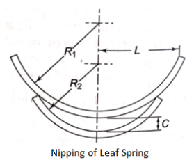
- As shown in figure, the full length leaf is given a greater radius of curvature than the adjacent leaf.
- This will leave a gap or clearance space between leaves.
- When the center clip is drawn up by tightening U bolts, the upper leaf will bend back and have an initial stress opposite to that produced by the normal load P.
- The lower leaf will have an initial stress if the same nature as that produced by normal load P
- When the normal load is applied, the stress in the upper leaf is relieved and then increased in the normal way.
- The initial gap between the leaves can be adjusted in such a way that under maximum load condition, the stress in all leaves will be same.
- The initial gap C between extra full length leaf and the graduated length leaf before assembly is called a 'nip'.
- Such prestressing, achieved by a difference in radii of curvature, is known as nipping.
- Nipping is common in automobile suspension springs.
Q12) Explain helical torsion spring.
A12)
- A helical torsion spring is a device used to transmit the torque to a particular component of a machine or mechanism.
- It is widely used in door hinges, brush holders, automobile starters and door locks.
- As shown in figure, the construction of the helical torsion spring is similar to that of compression or extension springs, except that the ends are formed in such a way that the spring is loaded by a torque about the axis of the coils.
- The helical torsion spring resist the bending moment (P×r), which tend to wind up the spring.
- The primary stresses in this spring are flexural in contrast with torsional shear stresses in compression for extension springs.
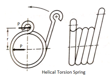
- Each individual section of the torsion spring is, in effect, a portion of a curved beam.
- Using the curved beam theory, the bending stresses are given by

Where K is the stress concentration factor due to curvature. For a wire of circular cross section,

Substituting the above values in equation (a) we get,

A.M. Wahl analytically derive the expression for stress concentration factor K. They are given by


Where  are stress concentration factors at the inner and outer fibres of the coil respectively.
Referring to figure

The strain energy stored in the spring is given by

The integration is to be carried over the entire length of the wire, Therefore,

The deflection in the direction of force P is approximately . Using Castigliano's theorem,

Substituting  we have

The stiffness of the helical torsion spring is defined as the bending moment required to produce unit angular displacement. Therefore,

The design of the helical torsion spring is based on the torque stress and torque deflection equations.
Q13) A compression coil spring made of an alloy steel is having the following specifications: Mean diameter of coil = 50 mm; Wire diameter = 5 mm; Number of active coils = 20. If this spring is subjected to an axial load of 500 N; calculate the maximum shear stress (neglect the curvature effect) to which the spring material is subjected.
A13)
534.7 Mpa
Given D=50mm d=5mm; *n=20; W=500 N
We know that the spring index

∴ Shear stress factor, 
And maximum shear stress (neglecting the effect of wire curvature),

Q14) A helical spring is made from a wire of 6 mm diameter and has outside diameter of 75 mm. If the permissible shear stress is 350 MPa and modulus of rigidity 84 kN/mm2, find the axial load which the spring can carry and the deflection per active turn.
A14)
Given d=6mm; 
We know that mean diameter of the spring,

∴ Spring index, 
Let W=Axial load, and  Deflection per active turn
1. Neglecting the effect of curvature
We know that the shear stress factor,

And maximum shear stress induced in the wire ().


We know that deflection of the spring,

∴ Deflection per active turn,

2. Considering the effect of curvature
We know that Wahl’s stress factor,

We also know that the maximum shear stress induced in the wire ()


And deflection of the spring,

∴ Deflection per active turn,

Q15) Design a spring for a balance to measure 0 to 1000 N over a scale of length 80 mm. The spring is to be enclosed in a casing of 25 mm diameter. The approximate number of turns is 30. The modulus of rigidity is 85 kN/mm2. Also calculate the maximum shear stress induced.
A15)
Given: W = 1000 N; δ = 80 mm; n = 30; G = 85 kN/mm2 = 85 × 103 N/mm2
Design of spring
Let  Mean diameter of the spring coil,
d= Diameter of the spring wire, and
C=Spring index=D/d
Since the spring is to be enclosed in a casing of 25 mm diameter, therefore the outer of the spring coil  should be less than 25 mm.
We know that deflection of the spring (δ)


Let us assume that d=4mm. Therefore

And 
We know that outer diameter of the spring coil,

Since the value of  is less than the casing diameter of 25mm, therefore the assumed dimension, d=4mm is correct.
Maxmimum shear stress induced
We know that Wahl’s stress factor,

Maximum shear stress induced


Q16) A compression coil spring made of an alloy steel is having the following specifications: Mean diameter of coil = 50 mm; Wire diameter = 5 mm; Number of active coils = 20. If this spring is subjected to an axial load of 500 N; calculate the maximum shear stress (neglect the curvature effect) to which the spring material is subjected.
A16)
Given D=50 mm; d-5mm; *n=20; W=500 N
We know that the spring index

∴ Shear stress factor
 and maximum shear stress (neglecting the effect of wire curvature)

Q17) A mechanism used in printing machinery consists of a tension spring assembled with a preload of 30 N. The wire diameter of spring is 2 mm with a spring index of 6. The spring has 18 active coils. The spring wire is hard drawn and oil tempered having following material properties:
Design shear stress = 680 MPa Modulus of rigidity = 80 kN/mm2 Determine: 1. The initial torsional shear stress in the wire; 2. Spring rate; and 3. The force to cause the body of the spring to its yield strength.
A17)
Given 
1. Initial torsional shear stress in the wire
We know that Wahl’s stress factor,

Initial torsional shear stress in the wire


2. Spring rate
We know that spring rate (or stiffness of the spring)

 Force to cause the body of the spring to its yield strength
Let W= Force to cause the body of the spring to its yield strength.
We know that design or maximum shear stress ()


Q18) Design a helical compression spring for a maximum load of 1000 N for a deflection of 25 mm using the value of spring index as 5.
The maximum permissible shear stress for spring wire is 420 MPa and modulus of rigidity is 84 kN/mm2
Take Wahl’s factor, 
A18)
Given W=1000 N; δ=25 mm; C=D/d=5; =420 Mpa=420 N/m ; G=94 kN/m
1. Mean diameter of the spring coil
Let D=Mean diameter of the spring coil, and
d= Diameter of the spring wire.
We know that Wahl’s stress factor,

And maximum shear stress ()


From table 23.2 we shall take a standard wire of size SWG 3 having diameter (d)=6.401mm.
Mean diameter of the spring coil

And outer diameter of the spring coil

2. Number of turns of the coils
Let n= Number of active turns of the coils.
We know that compression of the spring (δ),


For squared and ground ends, the total number of turns
n’=n+2=14+2=16
3. Free length of the spring
We know that free length of the spring
=n’d+δ+0.15δ=16×6.401+25+0.15×25=131.2mm
4. Pitch of the coil
We know that Pitch of the coil

Q19) Design a close coiled helical compression spring for a service load ranging from 2250 N to 2750 N. The axial deflection of the spring for the load range is 6 mm. Assume a spring index of 5. The permissible shear stress intensity is 420 MPa and modulus of rigidity, G = 84 kN/mm2.
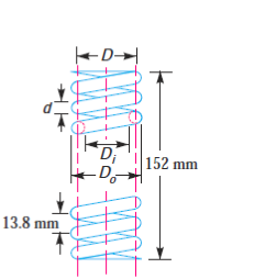
Neglect the effect of stress concentration. Draw a fully dimensioned sketch of the spring, showing details of the finish of the end coils.
A19)
Given: W1 = 2250 N; W2 = 2750 N; δ = 6 mm; C = D/d = 5; τ = 420 MPa = 420 N/mm2; G = 84 kN/mm2 = 84 × 103 N/mm2
1. Mean diameter of the spring coil
Let D=Mean diameter of the spring coil for a maximum load of

We know that twisting moment on the spring,

We also know that twisting moment (T)


From table 23.2 we shall take a standard wire of size SWG 3/0 having diameter (d)=9.49 mm
∴ Mean diameter of the spring coil,

We know that outer diameter of the spring coil,

And inner diameter of the spring coil,

2. Number of turns of the spring coil
Let n=Number of active turns
It is given that the axial deflection (δ) for the load range from 2250 N to 2750 N(ie for W=500N ) is 6mm.
We know that the deflection of the spring (δ)

For squared and ground ends, the total number of turns
n’=10+2=12
3. Free length of the spring
Since the compression produced under 500 N is 6 mm, therefore maximum compression produced under the maximum load of 2750 N is

We know that free length of the spring,


4. Pitch of the coil
We know that pitch of the coil
Q20) Design a helical spring for a spring-loaded safety valve (Ramsbottom safety valve) for the following conditions:
Diameter of valve seat = 65 mm; Operating pressure = 0.7 N/mm2; Maximum pressure when the valve blows off freely = 0.75 N/mm2; Maximum lift of the valve when the pressure rises from 0.7 to 0.75 N/mm2 = 3.5 mm; Maximum allowable stress = 550 MPa; Modulus of rigidity = 84 kN/mm2; Spring index = 6.
Draw a neat sketch of the free spring showing the main dimensions.
A20)
Given: D1 = 65 mm; p1 = 0.7 N/mm2; p2 = 0.75 N/mm2; δ = 3.5 mm; τ = 550 MPa = 550 N/mm2; G = 84 kN/mm2 = 84 × 103 N/mm2; C = 6
1. Mean diameter of the spring coil
Let D=Mean diameter of the spring coil, and
D=Diameter of the spring wire.
Since the safety valve is a Ramsbottom safety valve, therefore the spring will be under tension. We know that initial tensile force acting on the spring (i.e., before the valve lifts)

And maximum tensile force acting on the spring (ie when the valve blows off freely).

∴ Force which produces the deflection of 3.5 mm

Since the diameter of the spring wire is obtained for the maximum spring load  therefore maximum twisting moment on the spring.

We know that maximum twisting moment (T)


We shall take a standard wire of size SWG 2/0 having diameter (d)
= 8.839 mm Ans
 Mean diameter of the coil,

Outside diameter of the coil, 
And inside diameter of the coil, 
2. Number of turns of the coil
Let n=Number of active turns of the coil
We know that the deflection of the spring (δ)


For a spring having loop on both ends, the total number of turns,

3. Free length of the spring
Taking the least gap between the adjacent coils as 1 mm when the spring is in free state, the free length of the tension spring,

4. Pitch of the coil
We know that pitch of the coil

