Unit - 3
Cams
Q1) Define cams and Classification of cams?
A1) A cam is a mechanical component used for transmitting motion to a follower by direct contact. The driver of the system is known as the cam and the driven one is called the follower.
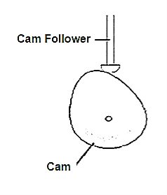
Fig.3.1. Cam
Classification of Cams:
Cams can be classified based on their physical shape.
- Disk or plate cam: The disk (or plate) cam has an irregular contour to impart a specific motion to the follower. The follower moves in a plane perpendicular to the axis of rotation of the cam shaft and is held in contact with the cam by springs or gravity.
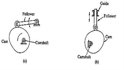
Fig. 3.2. Disk or plate cam
2. Cylindrical cam: The cylindrical cam has a groove cut along its cylindrical surface. The roller follows the groove, and the follower moves in a plane parallel to the axis of rotation of the cylinder.
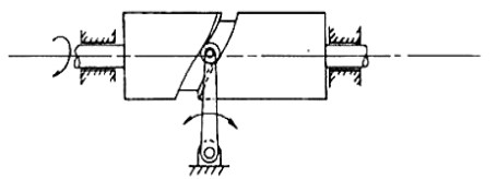
Fig. 3.3. Cylindrical cam
3. Translating cam: The translating cam is a contoured or grooved plate sliding on a guiding surface(s). The follower may oscillate (Fig.3a) or reciprocate (Fig. 3b). The contour or the shape of the groove is determined by the specified motion of the follower.
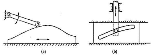
Fig. 3.4. Translating cam
Q2) What are the classification of follower?
A2)
(i)Based on surface in contact
a.Knife edge
b.Roller follower
c.Flat faced
d.Spherical follower
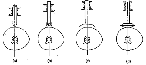
Fig.3.5. Spherical follower
(ii)Based on type of motion
(a)Oscillating
(b)Translating
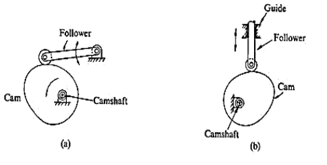
Fig.3.6. Based on type of motion
(iii)Based on line of motion
•Radial follower: The lines of movement of in-line cam followers pass through the centers of the camshafts.
•Off-set follower: For this type, the lines of movement are offset from the centers of the Cam shafts.
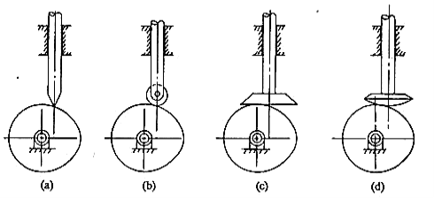
Fig.3.7. Based on line of motion
Q3) Draw the labelled displacement, velocity and acceleration diagrams for a follower when it moves with uniform velocity.
A3)
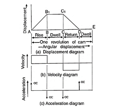
Fig.3.8. Follower when it moves with uniform velocity
Q4) Give detailed classification of followers.
A4) Types of followers
The followers may be classified as discussed below:
1. According to the surface in contact.
(a)Knife edge follower. When the contacting end of the follower has a sharp knife edge, it is called a knife edge follower.
(b) Roller follower. When the contacting end of the follower is a roller, it is called a roller follower.
(c) Flat faced or mushroom follower. When the contacting end of the follower is a perfectly flat face, it is called a flat faced follower and when the flat faced follower is circular, it is then called a mushroom follower.
(d) Spherical faced follower. When the contacting end of the follower is of spherical shape, it is called a spherical faced follower.
2.According to the motion of the follower.
(a) Reciprocating or translating follower. When the follower reciprocates in guides as the cam rotates uniformly, it is known as reciprocating or translating follower.
(b) Oscillating or rotating follower. When the uniform rotary motion of the cam is converted into predetermined oscillatory motion of the follower, it is called oscillating or rotating follower.
3. According to the path of motion of the follower.
(a) Radial follower. When the motion of the follower is along an axis passing through the centre of the cam, it is known as radial follower.
(b) Off-set follower. When the motion of the follower is along an axis away from the axis of the cam centre, it is called off-set follower.
Q5) Draw neat sketch of radial cam with follower and show on it
(i) Base circle.
(ii) Pitch point.
(iii) Prime Circle.
(iv) Cam profile
A5)
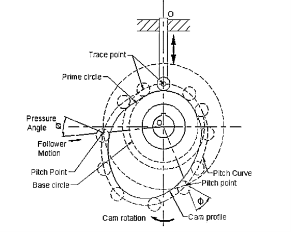
Fig.3.9. Radial cam with follower
Q6) What are the different types of follower motion? Also draw displacement diagram for uniform velocity.
A6) Different types of follower motions –
The follower during its travel may have one of the following motions: -
Uniform velocity, Simple harmonic motion, Uniform acceleration and retardation, Cycloidal motion.
Displacement Diagram of Uniform Velocity:
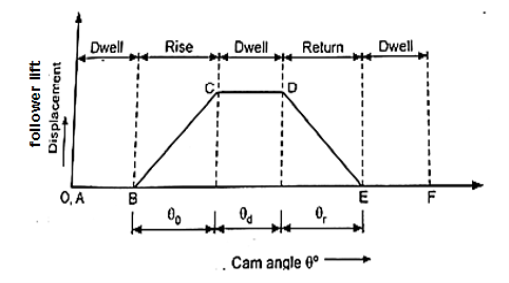
Fig.3.10. Displacement Diagram of Uniform Velocity
In above displacement diagram, abscissa(base) represents angular displacement of Cam in degrees (Cam angle) and ordinate represent lift or stroke of follower in mm. In uniform velocity, slope is constant. The lines AB, CD, and EF represent dwell period (no follower motion) and lines BC and DE represent rise and return stroke respectively, with uniform velocity.
Q7) Discuss the following motion of the follower by drawing the displacement velocity and acceleration diagram. (i) Uniform Velocity (ii) Uniform acceleration and retardation
A7)
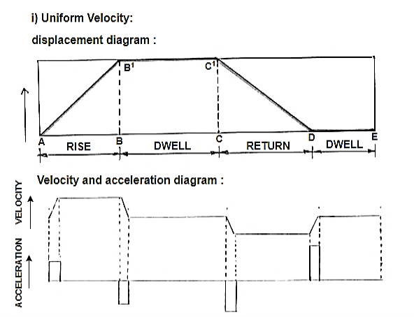
Fig.3.11. Displacement velocity and acceleration diagram
Uniform acceleration and retardation:
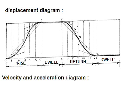
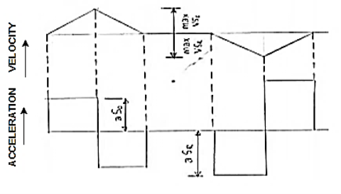
Fig.3.12. Displacement velocity and acceleration diagram
Q8) Draw profile of cam to raise the valve with S.H.M. Through 5cm in 120° of revolution, keep it fully raised through 30° and lower it with equal uniform acceleration and retardation through 90° of rotation. The valve remain closed during the rest of rotation. The diameter of the roller is 2 cm and the minimum radius of the cam is 5cm. The axis of the valve rod is offset 2cm from the axis of the shaft. Assume the cam rotating in clockwise direction.
A8)
Given: Follower rise = 120°
Dwell = 30°
Return = 90°
Minimum radius of the cam is 5cm
Roll Diameter = 2 cm
offset of follower = 2cm
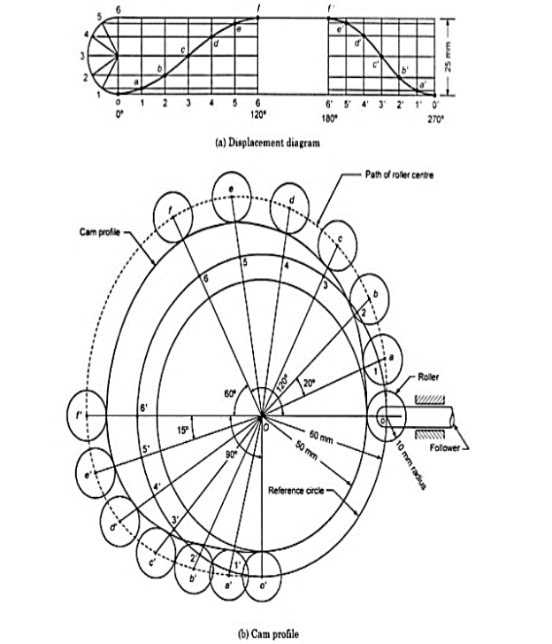
Fig.3.13. Cam with SHM
Q9) Define the following terms as applied to cam with neat sketch. (1) Pitch circle (2) Pressure angle (3) Stroke of follower (4) Module
A9)
(1) Pitch circle- Circle drawn from center of cam through pitch points.
(2) Pressure angle- Angle between direction of follower motion and normal to pitch curve.
(3) Stroke- Maximum travel of follower from its lowest position to top most position.
(4) Module –(Gears) – Ratio of pitch circle diameter in mm to No. Of teeth on gear.
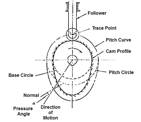
Fig.3.14. Cam with neat sketch
Q10) Why roller follower is preferred over a knife follower? State two advantages and application of roller follower.
A10)
In case of knife edge follower there is sliding motion between the contacting surface of cam and follower. Because of small contact area, there is excessive wear; therefore, it is not frequently used. Whereas in roller follower there is rolling motion between contacting surfacing and more contact area, therefore rate of wear is greatly reduced.
Advantages: i) Less wear, more life.
Ii) Less side thrust as compared to knife edge follower.
Application: Used in stationary oil and gas engines
Q11) Construct a cam profile with knife edge follower having an offset of 10 mm for the following data : Outstroke = 60° with SHM Dwell = 30° Return = 60° with uniform velocity and remaining is dwell period. Minimum radius of cam = 50 mm Lift of follower = 25 mm Consider the rotation of cam in clockwise direction.
A11)
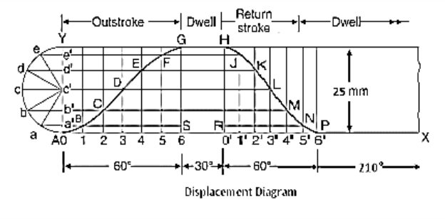
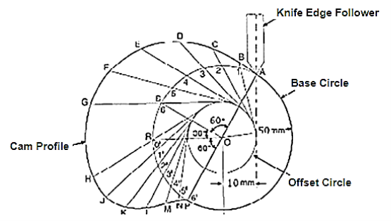
Fig.3.15. a cam profile with knife edge follower