Unit - 2
Introduction to bulk and sheet metal forming
Q1) A 300-mm-wide strip 25-mm thick is fed through a rolling mill with two powered rolls each of radius = 250 mm. The work thickness is to be reduced to 22 mm in one pass at a roll speed of 50 rev/min. The work material has a flow curve defined by K = 275 MPa and n = 0.15, and the coefficient of friction between the rolls and the work is assumed to be 0.12. Determine if the friction is sufficient to permit the rolling operation to be accomplished. If so, calculate the roll force, torque, and horsepower.
A1)
The draft attempted in this rolling operation is

The maximum possible draft for the given coefficient of friction is

Since the maximum allowable draft exceeds the attempted reduction, the rolling operation is feasible. To compute rolling force, we need the contact length L and the average flow stress . The contact length is given by

 is determined from the true strain:


And the power is obtained as

Q2) A cylindrical workpiece is subjected to a cold upset forging operation. The starting piece is 75mm in height and 50mm in diameter. It is reduced in the operation to a height of 36mm.The work material has a flow curve defined by K = 350MPa and n = 0.17. Assume a coefficient of friction of 0.1.Determine the force as the process begins, at intermediate heights of 62mm, 49 mm, and at the final height of 36 mm.
A2)
Workpiece volume

At the moment contact is made by the upper die, h = 75mmandthe force F = 0.At the start of yielding, h is slightly less than 75 mm, and we assume that strain = 0.002, at which the flow stress is

The diameter is still approximately D = 50mmand area

For these conditions, the adjustment factor Kf is computed as

The forging force is

At h = 62 mm,


Assuming constant volume, and neglecting barreling,

And


Similarly, at h = 49 mm, F = 955,642 N; and at h = 36 mm, F = 1,467,422 N
Q3) A billet 75mmlong and 25mmin diameter is to be extruded in a direct extrusion operation with extrusion ratio rx = 4.0. The extrudate has a round cross section. The die angle (half angle) = 900. The work metal has a strength coefficient = 415 MPa, and strain-hardening exponent = 0.18. Use the Johnson formula with a = 0.8 and b = 1.5 to estimate extrusion strain. Determine the pressure applied to the end of the billet as the ram moves forward.
A3)
Let us examine the ram pressure at billet lengths of L =75mm (starting value), L = 50 mm, L = 25 mm, and L =0.We compute the ideal true strain, extrusion strain using Johnson’s formula, and average flow stress:


L = 75mm: With a die angle of 900, the billet metal is assumed to be forced through the die opening almost immediately; thus, our calculation assumes that maximum pressure is reached at the billet length of 75mm. For die angles less than 90, the pressure would build to a maximum as the starting billet is squeezed into the cone-shaped portion of the extrusion die.
p = 373 ( 2.8795 + 2  ) = 3312 MPa
L = 50 mm; p = 373 ( 2.8795 + 2  ) = 2566 M Pa
L = 25 mm; p = 373 ( 2.8795 + 2  ) = 1820 M Pa
L = 1; Zero length is a hypothetical value in direct extrusion. In reality, it is impossible to squeeze all of the metal through the die opening. Instead, a portion of the billet (the “butt”
0 remains unextruded and the pressure begins to increase rapidly as L approaches zero. This increase in pressure at the end of the stroke is seen in the plot of ram pressure versus ram stroke in Figure 19.34. Calculated below is the hypothetical minimum value of ram pressure that would result at L = 0.
p = 373 ( 2.8795 + 2  ) = 1074 MPa
This is also the value of ram pressure that would be associated with indirect extrusion throughout the length of the billet.
Q4) Wire is drawn through a draw die with entrance angle =150. Starting diameter is 2.5 mm and final diameter = 2.0 mm. The coefficient of friction at the work–die interface = 0.07. The metal has a strength coefficient K = 205 MPa and a strain-hardening exponent n = 0.20. Determine the draw stress and draw force in this operation.
A4)
The values of D and L can be determined as.
= 0.88 + 0.12  = 1.16
The areas before and after drawing are computed as Ao = 4.91 mm2 and Af = 3.14 mm2. The resulting true strain ϵ = ln (4.91/3.14) = 0.446, and the average flows stress in the operations is computed:

Draw stress is given by Eq. (19.32):
σd = (145.4) ( 1 + 0.07/tan 15) (1.16)(0.446) = 94.1 MPa
Finally, the draw force is this stress multiplied by the cross-sectional area of the exiting wire:
F = 94.1(3.14) = 295.5 N
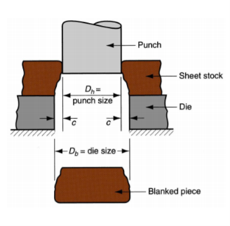
Q5) Around disk of 150-mm diameter is to be blanked from a strip of 3.2-mm, half-hard cold rolled steel whose shear strength = 310 MPa. Determine (a) the appropriate punch and die diameters, and (b) blanking force.
A5)
The clearance allowance for half-hard cold-rolled steel is Ac= 0.075. Accordingly,
c = 0.075 (3.2 mm) = 0.24 mm
The blank is to have a diameter = 150 mm, and die size determines blank size. Therefore,
Die opening diameter = 150.00 mm
Punch diameter = | 150 – 2(0.24) = 149.52 mm
To determine the blanking force, we assume that the entire perimeter of the part is blanked at one time. The length of the cut edge is
L = πDb = 150π = 471.2 mm
And the force is
F = 310(471.2(3.2) = 467.469 N[~53 tons]
Q6) A sheet-metal blank is to be bent. The metal has a modulus of elasticity = 205 (103) MPa, yield strength = 275 MPa, and tensile strength = 450 MPa. Determine (a) the starting blank size and (b) the bending force if a V-die is used with a die opening dimension = 25 mm.
A6)
(a)The starting blank =44.5mmwide. Its length = 38+Ab+25 (mm).For the included angle α’=1200, the bend angle α = 600.The value of Kba = 0.33 since R/t = 4.75/3.2 =1.48 (less than 2.0).
Ab = 2π  (4.75 + 0.33 3.2) = 6.08 mm
Length of the blank is therefore 38 + 6.08 + 25 = 69.08 mm.
(b) Force is obtained from Eq. (20.8) using Kbf = 1.33
F =  = 10,909 N
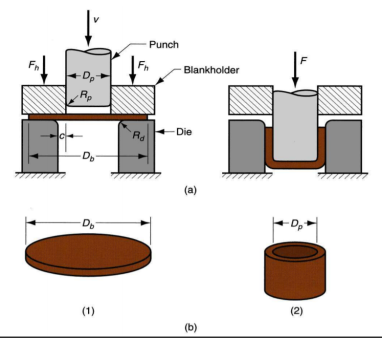
Q7) A drawing operation is used to form a cylindrical cup with inside diameter = 75 mm and height = 50mm. The starting blank size = 138 mm and the stock thickness = 2.4mm. Based on these data, is the operation feasible?
A7)
To assess feasibility, we determine the drawing ratio, reduction, and thickness-to-diameter ratio.
DR = 138/75 = 1.84
r = (138 – 75)/138 = 0.4565 = 45.65 %
t/Db = 2.4/138 = 0.017 = 1.7 %
According to these measures, the drawing operation is feasible. The drawing ratio is less than 2.0, the reduction is less than 50 %, and the t/Db ratio is greater than 1 %. These are general guidelines frequently used to indicate technical feasibility.
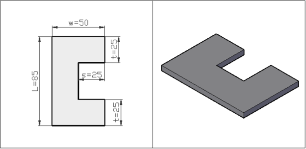
Q8) A blanking die is to be designed to blank the part outline shown in the figure below. The material is 4 mm thick stainless steel (the allowance for the stainless steel is a = 0.075). Determine the dimensions of the blanking punch and the die opening.

A8)
Since a = 0.075, the clearance is given by,
c = 0.075 (4) = 0.3 mm.
Blanking die dimensions: the same as for the part in the figure:
L = 85 mm w = 50 mm t = 25 mm s = 25 mm
Blanking punch dimensions:
Length L = 85 - 2(0.3) = 84.4 mm
Width w = 50 - 2(0.3) = 49.4 mm
Top and bottom t widths = 25 - 2(0.3) = 24.4 mm
The s = 25 mm inset dimension remains the same.
Q9) A blanking operation is to be performed on 2 mm thick cold rolled steel. The part is circular with diameter = 75 mm. Determine: a) the appropriate punch and die sizes for this operation if the allowance for the cold rolled steel is a = 0.075. b) the blanking force required if the steel has a shear strength = 325 MPa and the tensile strength is 450 MPa

A9)
(a) Since a = 0.075, the clearance is given by,
c = 0.075 (2) = 0.15 mm.
Thus the Punch diameter Dh is calculated as
Dh = Db - 2c = 75.0 - 2(0.15) = 74.70 mm.
And the Die diameter is Db
= 75 mm.
(b) the blanking force is given by
F = StL
The thick of the metal stock t is given by the problem as t = 2 mm
The length of cut edge is calculated as:
L = πD = 75π = 235.65 mm
Thus the blanking force is
F = 325 (2) (235.65) = 153,200 N
Q10) A cup is to be drawn in a deep drawing operation. The height of the cup is 75 mm and it’s inside diameter = 100 mm. The sheet metal thickness = 2 mm. If the blank diameter = 225 mm, determine (a) drawing ratio, (b) reduction, and (c) thickness-to-diameter ratio. (d) Does the operation seem feasible?

A10)
(a) Drawing ratio DR = Db/Dp= 225/100 = 2.25
(b) Reduction r = (Db - Dp)/Db = (225 - 100)/225 = 0.555 = 55.5%
(c) Thickness-to-diameter ratio t/Db = 2/225 = 0.0089 = 0.89%
(d) Feasibility? No!
DR is too large (greater than 2),
r is too large (greater than 50%),
And t/D is too small (less than 1%)
Q11) In a machining operation that approximates orthogonal cutting, the cutting tool has a rake angle = 100. The chip thickness before the cut to = 0.50 mm and the chip thickness after the cut tc = 1.125 in. Calculate the shear plane angle and the shear strain in the operation.
A11)
The chip thickness ratio can be determined as
r = 0.50/1.125 = 0.444
The shear plane angle is given by
Tan = 
= 25.4o
Finally, the shear strain is calculated as
γ = tan (25.4 – 10) + cot 25.4
γ = 0.275 + 2.111 = 2.386
Q12) Suppose in above example cutting force and thrust force are measured during an orthogonal cutting operation: Fc = 1559 N and Ft = 1271 N. The width of the orthogonal cutting operation w = 3.0 mm. Based on these data, determine the shear strength of the work material.
A12)
From Example 1, rake angle a = 100, and shear plane angle f = 25.40. Shear force can be computed as
Fs = 1559 cos 25.4 -1271 sin 25.4 = 863 N
The shear plane area is given by
As = 
Thus the shear stress, which equals the shear strength of the work material, is
τ = S = 863/3.497 = 247 N/mm2 = 247 MPa
Q13) Using the data and results from our previous examples, determine (a) the friction angle and (b) the coefficient of friction.
A13)
(a) From Example 1,  = 100, and
  = 25.40. The friction angle can be estimated:

(b) The coefficient of friction is given by

Q14) The cutting force and thrust force in an orthogonal cutting operation are 1470 N and 1589 N, respectively. The rake angle = 5°, the width of the cut = 5.0 mm, the chip thickness before the cut = 0.6, and the chip thickness ratio = 0.38. Determine (a) the shear strength of the work material and (b) the coefficient of friction in the operation.
A14)
(a) φ = tan-1(0.38 cos 5/(1 - 0.38 sin 5)) = tan-1(0.3916) = 21.38°
Fs = 1470 cos 21.38 – 1589 sin 21.38 = 789.3 N
As = (0.6)(5.0)/sin 21.38 = 3.0/.3646 = 8.23 mm2
S = 789.3/8.23 = 95.9 N/mm2 = 95.9 MPa
(b) φ = 45 + α/2 - β/2; rearranging,
β = 2(45) + α - 2φβ = 2(45) + α - 2(φ) = 90 + 5 – 2(21.38) = 52.24°
μ = tan 52.24 = 1.291
Q15) In an orthogonal cutting operation, the rake angle = -5°, chip thickness before the cut = 0.2 mm and width of cut = 4.0 mm. The chip ratio = 0.4. Determine (a) the chip thickness after the cut, (b) shear angle, (c) friction angle, (d) coefficient of friction, and (e) shear strain.
A15)
(a) r = to/tc, tc = to/r = 0.2/.4 = 0.5 mm
(b) φ = tan-1(0.4 cos(–5)/(1 - 0.4 sin(–5))) = tan-1(0.3851) = 21.1°
(c) β = 2(45) + α - 2(φ) = 90 + (-5) - 2(21.8) = 42.9°
(d) μ = tan 42.9 = 0.93
(e) γ = cot 31.8 + tan(31.8 - 15) = 2.597 + 0.489 = 3.09
Q16) A carbon steel bar 7.64 inch in diameter has a tensile strength of 65,000 lb/in2 and a shear strength of 45,000 lb/in2. The diameter is reduced using a turning operation at a cutting speed of 400 ft/min. The feed is 0.011 in/rev and the depth of cut is 0.120 in. The rake angle on the tool in the direction of chip flow is 13°. The cutting conditions result in a chip ratio of 0.52. Using the orthogonal model as an approximation of turning, determine: (a) the shear plane angle, (b) shear force, (c) cutting force and feed force, and (d) coefficient of friction between the tool and chip.
A16)
(a) φ = tan-1(0.52 cos 13/(1 - 0.52 sin 13)) = tan-1(0.5738) = 29.8°
(b) As = tow/sin φ = (0.011)(0.12)/sin 29.8 = 0.00265 in2.
Fs = AsS = 0.00587(40,000) = 119.4 lb
(c) β = 2(45) + α - 2(φ) = 90 + 10 - 2(29.8) = 43.3°
Fc = Fscos (β–α)/cos (φ + β–α)
Fc = 264.1 cos (43.3 - 13)/cos (29.8 + 43.3 - 13) = 207 lb
Ft = Fssin (β–α)/cos (φ + β–α)
Ft = 264.1 sin (43.3 - 13)/cos (29.8 + 43.3 - 13) = 121 lb
(d) μ = tan β = tan 43.3 = 0.942
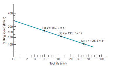
Q17) Determine the values of C and n in the plot of graph, using two of the three points on the curve and solving simultaneous equations of the form of equation .
.

A17)
Choosing the two extreme points: v =160m/min, T = 5min;andv = 100m/min,
T = 41 min; we have
160(5)n = C
100(41)n = C
Setting the left-hand sides of each equation equal,
160(5)n = 100(41)n
Taking the natural logarithms of each term,
Ln (160) + n ln(5) = ln (100) + n ln (41)
5.0752 + 1.6094 n = 4.6052 + 3.7136 n
0.4700 = 2.1042 n
n = 0.4700/2.1042 = 0.223
Substituting this value of n into either starting equation, we obtain the value of C:
C = 160(5)0.223 = 229
Or
C = 100(41)0.223 = 229
The Taylor tool life equation for the data of graph is therefore
VT0.223 = 229
Q18) A series of tool life tests are conducted on two work materials under identical cutting conditions, varying only speed in the test procedure. The first material, defined as the base material, yields a Taylor tool life equation vT0.28 = 350, and the other material (test material) yields a Taylor equation vT0.27 = 440, where speed is in m/min and tool life is in min. Determine the machinability rating of the test material using the cutting speed that provides a 60-min tool life as the basis of comparison. This speed is denoted by v60.
A18)
The base material has a machinability rating = 1.0. Its v60 value can be determined from the Taylor tool life equation as follows:

The cutting speed at a 60-min tool life for the test material is determined similarly:

Accordingly, the machinability rating can be calculated as

Q19) Machinability ratings are to be determined for a new work material using the cutting speed for a specified tool life as the basis of comparison. For the base material (B1112 steel), test data resulted in Taylor equation parameter values of n = 0.24 and C = 450, where speed is m/min and tool life is min. For the new material, the parameter values were n = 0.28 and C = 490. Cemented carbide tools were used. Compute machinability ratings for the new material using as the tool life criterion (a) 60 min, (b) 10-min, and (c) 1.0 min. (d) What do the results show about the difficulties in machinability measurement?
A19)
(a) Base material: v60 = 450/600.24 = 168.4 m/min
New material: v60 = 490/600.28 = 155.7 m/min
MR = 155.7/168.4 = 0.925 = 92.5%
(b) Base material: v10 = 450/100.24 = 259.0 m/min
New material: v10 = 490/100.28 = 257.2 m/min
MR = 257.2/259.0 = 0.993 = 93.3%
(c) Base material: v1 = 450/10.24 = 450 m/min
New material: v1 = 490/10.28 = 490 m/min
MR = 490/450 = 1.089 = 108.9%
(d) Different test conditions often result in different machinability results.
Q20) Machinability ratings are to be determined for a new steel. For the base material (B1112), test data resulted in Taylor equation parameters n = 0.28 and C = 500. For the new material, the Taylor parameters were n = 0.25 and C = 430. Cutting speed units are m/min, and tool life units are min. The tooling was cemented carbide. (a) Compute machinability ratings for the new material using the following criteria: (a) cutting speed for a 30-min tool life and (b) tool life for a cutting speed of 150 m/min.
A20)
(a) Base material: v30 = 500/30.28 = 192.9 m/min
New material: v30 = 430/30.25 = 183.7 m/min
MR = 183.7/182.8 = 0.95 = 95%
(b) Base material: T150 = (500/150)1/.28 = (3.33)3.571= 73.7 min
New material: v10 = (430/150)1/.25 = (2.87)4.0 = 67.8 min
MR = 67.8/73.7 = 0.92 = 92%