Unit - 3
Joining/Fastening Processes
Q1) Explain welding process. Give its advantages and limitations.
A1)Welding is referred a material joining process where two or more parts are joined at their contacting surfaces through appropriate application of heat and pressure. Most of the welding processes are achieved via means of heat alone or with pressure alone. In few welding processes, filler material is introduced to facilitate bonding. The assemblage of elements which are joined by welding is known as weldment. Welding is most commonly related to metal parts, whereas the process is additionally used for joining plastics.
Advantages of welding:
- Welding provides a permanent joint and hence welded parts become a single entity.
- Welding is the most cost-efficient way to join components in terms of material utilization and fabrication costs.
- The welded joint may have more potential (simply may be stronger) compared to the parent materials if a filler metal is used which has strength properties that are superior to that of parents. For this proper welding techniques must be used.
- Welding is not limited to the factory environment and can be achieved in the field.
Limitations of welding:
- Many welding processes involve the use of high energy and hence are very dangerous.
- Since welding accomplishes a everlasting bond among the components, it does not permit for handy disassembly. If the product is to be disassembled (example, for repair or maintenance), then welding must not be used as the assembly approach.
- Many welding operations are performed manually and are expensive for labor cost. Many welding operations are considered ‘‘skilled trades,’’ and the labor to perform these operations may be less.
- The welded joint may suffer from specific quality defects that are hard to detect. These defects can reduce the strength of the joint.
Q2) Classify welding process.
A2)Welding processes are divided into two major groups:
(1) fusion welding (liquid-state welding) and (2) solid-state welding.
Fusion Welding Process:
Fusion-welding processes make use of heat to melt the parent metals. In most of fusion welding operations, a filler metal is introduced to accelerate the process and offer strength to the welded joint. When there is no filler metal added, in a fusion-welding operation, is termed as an autogenous weld. The fusion category contains the most globally used welding processes that can be divided into the following types:
- Arc-welding: Arc welding is welding processes where heating of the metals is achieved by an electric arc. Few arc welding processes also apply pressure at the time of the process and most of them make use of a filler metal.
- Resistance welding: Resistance welding achieves bonding by using heat from electrical resistance to the flow of a current passing among the faying surfaces of two elements held collectively under pressure.
- Oxyfuel gas welding: These joining processes uses an oxyfuel gas, like a mixture of oxygen and acetylene, to create a hot flame for melting the parent metal and filler metal.
Solid State Welding Process:
Solid-state welding is a joining processes where joint results through application of pressure alone or by a mixture of heat and pressure. If heat is used for welding, the temperature in the operation is below the melting point of the metals that are being welded. There is no use of filler metal in solid state welding. Solid state welding is categorized into following types:
- Diffusion welding: When two surfaces are held together under pressure at an elevated temperature and the parts are joined then the welding process is termed by solid-state diffusion.
- Friction welding: Joint is achieved by the heat of friction between two surfaces.
- Ultrasonic welding: Moderate pressure is applied between the two parts and an oscillating motion at ultrasonic frequencies is used for welding. The direction of ultrasonic frequencies is parallel to the contacting surfaces. The combination of normal forces along with the vibratory forces leads to shear stresses which remove surface films and acquire atomic bonding of the surfaces.
Q3) Define power density, heat transfer factor and melting factor.
A3)
Power Density:
A)Power density can be referred as power transferred to the work per unit of the surface area.
Power density is given by,
Where,
P is the power entering the surface.
A is the surface area in which power is entering
Heat Transfer Factor
Heat transfer factoris defined as the ratio of the original heat received by the workpiece to the total heat generated at the source. It is denoted by  .
.
Melting factor
Melting factoris defined as the heat used for welding to the heat received at the workpiece. It is denoted by  .
.
Hence, heat available at welding is given by,

Where,
 is the net heat available for welding process
H is total heat generated at the source of heat.
Q4) A heat source transfers 3000 W to the surface of a metal part. The heat impinges the surface in a circular area, with intensities varying inside the circle. The distribution is as follows: 70% of the power is transferred with in a circle of diameter = 5 mm, and 90% is transferred within a concentric circle of diameter = 12 mm. What are the power densities in (a) the 5-mm diameter inner circle and (b) the 12-mm-diameter ring that lies around the inner circle?
A4)
(a) The inner circle has an area A = π(5)2/4 = 19.63 mm2.
The power inside this area P = 0.70 3000 = 2100 W.
Thus the power density PD = 2100/19.63 = 107 W/mm2.
(b) The area of the ring outside the inner circle is A = π(122 – 52)/4 = 93.4 mm2.
The power in this region P = 0.9 (3000) – 2100 = 600 W.
The power density is therefore PD 600/93.4 = 6.4 W/mm2.
Q5) The power source in a particular welding setup generates 3500 W that can be transferred to the work surface with a heat transfer factor = 0.7. The metal to be welded is low carbon steel, whose melting temperature, from Table 29.2, is 1760oK. The melting factor in the operation is 0.5. A continuous fillet weld is to be made with a cross-sectional area = 20mm2. Determine the travel speed at which the welding operation can be accomplished.
A5)
Let us first find the unit energy required to melt the metal
Um = 3.33(10-6) 17602 = 10.3 J/mm3
We have v = f1f2RH/UmAw
And solving for the conditions of the problem
v = 
Q6) What are the design considerations in welding?
A6)
If an assembly is to be permanently welded, the following guidelines should be followed by designer
- Design for welding: The most primary guideline is that the product should be designed from the beginning as a welded assembly however no longer as a casting or forging or other formed shape.
- Minimum parts: Welded assemblies must include of the minimal quantity of parts possible. For example, it is generally more economical to carry out simple bending operations on a part instead to weld an assembly from flat plates and sheets.
The following design considerations apply to arc welding:
- Good fit-up of partsto be welded is very important to maintain dimensional control and minimize distortion. Machining is few times needed to achieve satisfactory fit-up.
- The assembly must have access room to allow the welding gun to reach the welding area
- Whenever possible, design of the assembly must enable flat welding to be performed, as this is the quickest and most feasible welding position. The possible welding positions are defined in Figure below. The overhead position is the most difficult.

Figure Welding positions (defined here for groove welds): (a) flat, (b) horizontal, (c) vertical, and (d) overhead.
The following design guidelines apply to resistance spot welding:
- Low-carbon sheet steel up to 3.2 mm is the ideal metal for resistance spot welding.
- Additional strength and stiffness may be received in large flat sheet metallic components by: (a) spot welding reinforcing parts into them, or (b) forming flanges and embossments into them.
- The spot-welded assembly need to offer access for the electrodes to attain the welding area.
- Sufficient overlap of the sheet-metal parts should be required for the electrode tip to make proper contact in spot welding.
Q7) What is solid and liquid state welding? Explain Brazing process.
A7)
Solid and liquid state joining process is referred to the joining process in which filler metal is melted or is in liquid state and is used for to create a bond between two solid metals.
Three different processes which are brazing, soldering and adhesive bonding are included in solid and liquid state joining process. The physical phenomenon associated with each of these processes is same but differ only in the metallurgical aspect. In these processes, the bulk material is not melted. A molten filler metal is used to provide a joint. The working temperature of these process is generally below the melting point of the base or parent metal.
Brazing
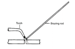
Brazing is a joining process where a filler metal is melted and disbursed through a capillary action among the two surfaces of the metal parts to be joined. Here, the distance between two mating surfaces is very less. Melting of the base metals doesn’t occur in brazing. In brazing only the filler material is melted. In brazing the filler metal (also called the brazing metal), has a melting temperature that is above 450oC but below the melting point of the base metals to be joined. The brazed joint is much stronger compared to the filler metal from which it has been created upon solidification. This is because of the less part clearances used in brazing. The other reasons for stronger brazed bond is the metallurgical bonding that takes place among base and filler metals as well as the geometric constrictions which are imposed at the joint via base parts.
Q8) Explain adhesive bonding. Give its conditions.
A8)
Adhesive bonding is referred to a joining process where a filler material is used to hold two or more than two closely spaced parts together via means of a surface attachment. The filler material which helps in binding of these parts together is the referred to as adhesive. Adhesive is a nonmetallic substance, generally a polymer. Adherends are the parts that are being joined together.
A large number of commercially available adhesives are cured by various mechanisms and are suited to the bonding of various materials. Curing is defined as the process where the physical properties of adhesive are changed from a liquid to a solid, generally by chemical reaction, to achieve the surface attachment of the parts. The chemical reaction involves polymerization, condensation, or vulcanization. Curing is often motivated by heat or a catalyst, and pressure is sometimes applied between the two parts to activate the bonding process. If heat is required, the curing temperatures are relatively low, and so the materials being joined are usually unaffected. The curing or hardening of the adhesive requires time, called curing time or setting time. In some cases, setting time is generally significant.
Joint strength in adhesive bonding is determined by the strength of the adhesive itself and the strength of attachment between adhesive and each of the adherends.
Following are the conditions for adhesive bonding
- Surfaces of the adherend must be clean, which means that surfaces should be free of dirt, oil, and oxide films. These things may interfere with accomplishing close contact among adhesive and adherend. For this special preparation of the surfaces is often required.
- In the initial liquid form, the adhesive should achieve thorough wetting of the adherend surface.
- The surfaces must not be perfectly smooth. Slightly roughened surface maximizes the effective contact area and it promotes mechanical interlocking.
Q9) Explain Joining/ fastening processes.
A9)
The process of joining two similar or dissimilar materials is referred as joining process. The joining process is referred as fastening process, when there is the use of fasteners to joint them.
The term ‘joining’ is mainly used for welding, brazing, soldering, and adhesive bonding that form a permanent or a temporary joint between the parts. Permanent joint is referred to a joint that cannot easily be separated while temporary joint is the joint that can be easily separated when required.
The joining process can be divided into a liquid state joining or a solid-state joining process.
These processes are primarily used for the assembly of the machine to join various parts either permanently or temporarily.
Joining process generally contains the processes like welding, brazing, soldering, fastening, adhesive bonding, etc.
Welding process is the most widely used process for a permanent joint. While fastening process is most widely used process for temporary joint.
Fastening process can be divided into three types:
- Permanent mechanical fastening: When the joint required is permanent, then these fastening processes are used. It includes riveting, flanging, staking, stapling, crimping, seaming etc.

b. Semi-permanent fastening process: It includes snap fit, Blind rivet, press fit, etc.
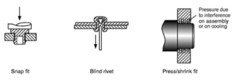
c. Non-permanent fastening process: When the joint required is temporary, then non-permanent fastening process is used. It includes Retaining, self-tapping, nut-bolt assembly, etc.

Q10) Write Advantages and limitations of Brazing
A10)
Advantages of Brazing
- Some brazing methods may be performed fastly and consistently, hence allowing high cycle rates and automated production
- Brazing can be used to join thin-walled parts which cant be welded
- Any metals may be joined, including dissimilar metals
- Problems with the heat-affected zone in the base metal near the joint are reduced.
- Some methods enable multiple joints to be brazed simultaneously;
- In general, less heat and power are required than in fusion welding
Limitation of Brazing:
- High service temperatures may weaken a brazed joint
- Although strength of a good brazed joint is greater than that of the filler metal, it is usually to be less compared to that of the base metals
- Joint strength is usually less compared to a welded joint
Q11) Explain soldering.
A11)
Soldering
Soldering is similar to brazing and can be defined as a joining process in which a filler metal, with melting point below 450oC, is melted and disbursed through capillary action among two surfaces of the metal parts to be joined. Similar to brazing, melting of the parent metals doesn’t occur but the filler metal is melted and it combines with the parent metal creating a metallurgical bond. Surfaces to be soldered should be pre-cleaned. This is done such that they are free of oxides, oils, etc. Proper flux should be applied to the soldering surfaces when the surfaces are heated. Filler metal, known as solder is added to the joint that disburses itself within the closely fitting parts of two materials. In industry, soldering is very closely connected to the electronics assembly.
Advantages of soldering:
- It requires low energy input relative to brazing and fusion welding
- Variety of heating methods are available
- It gives good electrical and thermal conductivity in the joint
- It has capability to make air-tight and liquid-tight seams for containers
- It is easy to repair and rework.
Limitations of soldering:
- Soldered joint has low joint strength unless reinforced by mechanically means.
- It can have possible weakening or melting of the joint in elevated temperature service.
Q12) Explain the fundamentals of Rapid Prototyping process.
A12)
Fundamentals of Rapid Prototyping
The Rapid Prototyping Wheel depicting the 4 major aspects of RP

- Input
- Input refers to the electronic data needed to describe the physical model with 3D data.
- There are two possible beginning points, which is a computer model or a physical model.
- The computer model created by a CAD system can be either a surface model or a solid model
- On the other hand, 3D data from the physical model is not at all straightforward.
- It requires information acquisition by a approach known as reverse engineering.
b. Method
The method employed by all vendors can be generally categorized into the following types:
• cutting and gluing or joining,
• photo-curing,
• melting and solidifying or fusing and joining or binding.
Photo-curing can be further divided into categories of
• single laser beam,
• masked lamp
• double laser beams and
c. Material
- The initial state of material are either available in solid, liquid or powder state.
- In solid state, material may be available in different forms like pallets, wire or laminates.
d. Application
- Applications can be grouped into:
• Design
• Engineering, Analysis and Planning
• Tooling and Manufacturing
Q13) Explain the basic steps in rapid prototyping.
A13)
Basic Steps in Rapid Prototyping Process
i) CAD Model Creation:
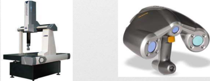
- First, the object that is to be created is modeled with the help of a Computer-Aided Design (CAD) software package or coordinate measuring system or also by laser scanner.
- Solid modelers, for example Pro/ENGINEER, tend to show 3-D objects more perfectly compared to wire-frame modelers like AutoCAD, and hence yield good results.
- This process is same for all of the RP creation techniques.
Ii) Conversion to STL Format:
- The STL format has been adopted, in order to establish consistency, as the standard file format of the rapid prototyping industry and acts as the interface between CAD software and machines.
- The second step in rapid prototyping is to translate the CAD file into STL format. This format gives a 3D surface an assembly of planar triangular facets.
- STL files makes use of a planar elements because they cannot represent curved surfaces perfectly. Maximizing the quantity of triangles improves the approximation. While minimizing these numbers reduces the quality.

Iii) Slice the STL File:
- In the third step, a pre-processing program of rapid prototyping is to prepare the STL file to be generated.
- The pre-processing software cuts the STL model into many number of layers, thickness ranging from 0.01 mm to 0.7 mm, depending on the creation method.
Iv) Layer by Layer Construction:
- The fourth step is the actual construction of the part.
- RP machines create one layer at one time from polymers, paper, or from powdered metal.
- Most machines are not autonomous, requiring some human intervention.
v) Clean and Finish:
- The last step in rapid prototyping is post-processing. This includes removal of the prototype from the machine and detaching the supports if any.
- Some photosensitive materials require to be completely cured prior use
- Prototypes might also need minor cleaning as well as surface treatment.
Q14) Classify Rapid Prototyping.
A14)
Classification of Rapid Prototyping
Based on initial form of material used, the rapid prototyping systems are broadly classified into three categories.
a) LIQUID-BASED
- In liquid-based Rapid prototyping systems, the initial form of the material is in liquid state.
- In a process generally called as curing, the liquid material is changed into the solid state.
- The liquid used is organic resin that cures or solidifies under the exposure of light.
- Examples:
a) Stereolithography (SLA)
b) Polyjet Modelling
b) SOLID-BASED
- Except for powder, solid-based rapid prototyping systems have all forms of material in the solid state only.
- The solid form of material can contain the shape in the type of a wire, a roll, laminates and pallets.
- It does not include powder form.
- Examples:
a) Fused Deposition Modelling (FDM)
b) Laminated Object Modelling (LOM)
c) POWDER-BASED
- In a strict sense, powder is by-and-large in the solid state.
- This category is intentionally kept outside the solid-based rapid prototyping systems to mean powder material in grain-like form.
- Examples:
a) Selective Laser Sintering (SLS)
b) 3D- Printing
Q15) Write a note on Rapid Tooling
A15)
Rapid-prototyping techniques have made possible much faster product development times, and they are having a major effect on other manufacturing processes. When proper materials are being used, rapid-prototyping machinery can create blanks for investment casting or similar processes. Hence that metallic parts may now be received fastly and economically, even for lot sizes as little as one part.
Such techniques also can be applied to create molds for operations (like injection molding, sand and shell mold casting, and also forging), thereby significantly reducing the lead time between design and manufacture.
Many approaches have been devised for the fast production of tooling (RT) via means of rapid-prototyping processes.
Rapid tooling is the process of manufacturing the tools using the rapid prototyping technique. It is widely used in many areas of industries.
The advantages to rapid tooling include the following:
- There is a much decrease in lead time.
- The high cost of labor and short supply of skilled pattern makers can be overcome.
- Lightweight castings can be produced more easily because hollow designs can be adopted easily
The principal shortcoming of RT is the potentially decreased tool or pattern life as compared to the ones acquired from machined tool and die materials, like tool steels or tungsten carbides.
The easiest method of making use of rapid-prototyping operations to different manufacturing processes is in the direct generation of patterns or molds.
Q16) Classify Rapid Tooling.
A16)
Classification of Rapid Tooling:
A] Classification method of tooling:
a. Direct Tooling
Direct Tooling is a process of making the tool, die or mold directly from the CAD data, using rapid prototyping process. For example, in injection molding, the main cavity, cores, runner, ejection system, etc. can be produced directly using rapid prototyping process.
b. Indirect Tooling
Indirect tooling is the process of making the master patterns for making tool, die or mold from CAD data, using rapid prototyping process.
It is not a tool production process but is a pre-production process. SLA, which gives a good accuracy and surface finish, is used as indirect tooling process.
B] Classification based on Material used:
a. Hard Tooling
Hard tooling is the process of making the tool, die or mold from hard materials like steel, using rapid prototyping process.
b. Soft Tooling
Soft tooling is the process of making the tool, die or mold from soft materials like silicon rubber, epoxy resin, low melting point alloys, etc. using rapid prototyping process.