Unit IV
Networks Layers: Services and Addressing
- Explain Network Layer Services?
Network layer is the third layer in OSI model of computer networks. Its main function is to transfer network packets from the source to destination. It is involved both at source host and the destination host.
At the source it accepts a packet from the transport layer, encapsulates it in a datagram and then deliver the packet into the data link layer so that it can sent further to the receiver.
At the destination, the datagram is decapsulated, the packet is extracted and delivered to the corresponding transport layer.
The services offered by the network layer protocol are as follows:
- Packetizing –
The process of encapsulating the data received from upper layers of the network called as payload in a network layer packet at the source and decapsulating the payload from the network layer packet at the destination is known as packetizing.
The source host adds a header that contains the source and destination address and some other relevant information required by the network layer protocol to the payload received from the upper layer protocol, and delivers the packet to the data link layer.
The destination host receives the network layer packet from its data link layer, decapsulates the packet, and delivers the payload to the corresponding upper layer protocol.
2. Routing and Forwarding –
These are two other services offered by the network layer. In a network, there are number of roots available from the source to the destination.
The network layer specifies some strategies which find out the best possible route. This process is referred to as routing.
There are several routing protocols used in this process and they should run to help the routers coordinate with each other and help in establishing communication throughout the network.
Forwarding is defined as the action applied by each router when a packet arrives at one of its interfaces. When a router receives a packet from one of its attached networks, it needs to forward the packet to another attached network uncasting or to some attached networks.
2.Explain static and dynamic configuration?
A static IP address is simply an address that does not change. Once your device is assigned a static IP address that number typically stays the same until the device is decommissioned or your network architecture changes.
Static IP addresses are assigned by Internet Service Providers (ISPs). Your ISP may or may not allocate you a static IP address depending on the nature of your service agreement.
A static IP address may be IPv4 or IPv6 in this case the important quality is static.
Dynamic IP address
We use dynamic addresses because IPv4 does not provide enough static IP addresses to go around.
For example, a hotel probably has a static IP address, but each individual device within its rooms would have a dynamic IP address.
On the internet, your home or office may be assigned a dynamic IP address by your ISP's DHCP server.
Your home or business network, the dynamic IP address for your devices -- whether they are personal computers, smartphones, streaming media devices, tablet, what have you -- are probably assigned by your network router.
Dynamic IP is the standard used by and for consumer equipment.
3. Explain classful and classless addressing ?
With classful routing, IP v4 addresses were divided into five classes(A to E).
Classes A-C : unicast addresses
Class D : multiclass addresses
Class E : Reserved for future use.
- Class A
In a class A address, the first bit of the first octet is always ‘0’. Thus, class A addresses range from 0.0.0.0 to 127.255.255.255(as 01111111 in binary converts to 127 in decimal).
The first 8 bits or the first octet denote the network portion and the rest 24 bits or the 3 octets belong to the host portion.
Example 10.1.1.1
Exception
-127.X.X.X is reserved for loopback
-0.X.X.X is reserved for default network.
Therefore, the actual range of class A addresses is: 1.0.0.0 to 126.255.255.255
- Class B
In a class B address, the first octet would always start with ’10’. Thus, class B addresses range from 128.0.0.0 to 191.255.255.255.
The first 16 bits or the first two octets denote the network portion and the remaining 16 bits or two octets belong to the host portion.
Example 172.16.1.1
- Class C
In a class C address, the first octet would always start with ‘110’. Thus, class C addresses range from 192.0.0.0 to 223.255.255.255. The first 24 bits or the first three octets denote the network portion and the rest 8 bits or the remaining one octet belong to the host portion.
Example 192.168.1.1
- Class D
Class D is used for multicast addressing and in a class D address the first octet would always start with ‘1110’. Thus, class D addresses range from 224.0.0.0 to 239.255.255.255.
Example 239.2.2.2
Class D addresses are used by routing protocols like OSPF, RIP, etc.
- Class E
Class E addresses are reserved for research purposes and future use. The first octet in a class E address starts with ‘1111’. Thus, class E addresses range from 240.0.0.0 to 255.255.255.255.
Classless Inter-Domain Routing (CIDR)
CIDR or Class Inter-Domain Routing was introduced in 1993 to replace classfull addressing. It allows the user to use VLSM or Variable Length Subnet Masks.
CIDR notation:
In CIDR subnet masks are denoted by /X.
For example, a subnet of 255.255.255.0 would be denoted by /24.
To work a subnet mask in CIDR, we must first convert each octet into its respective binary value.
For example, if the subnet is of 255.255.255.0. Then :
- First Octet:
- 255 has 8 binary 1’s when converted to binary
Second Octet:
- 255 has 8 binary 1’s when converted to binary
- Third Octet:
- 255 has 8 binary 1’s when converted to binary
- Fourth Octet:
- 0 has 0 binary 1’s when converted to binary
Therefore, in total there are 24 binary 1’s, so the subnet mask is /24.
While creating a network in CIDR, a person must make sure that the masks are contagious that is subnet mask like 10111111.X.X.X can’t exist.
With CIDR, we can create Variable Length Subnet Masks, leading to less wastage of IP addresses.
4. Explain Special addresses?
There are several IP addresses that are special in one way or another. These addresses are for special purposes or are to be put to special use.
•Addresses significant to every IP subnet
- Network Address
- Broadcast Address
•Addresses significant to individual hosts
- Loopback Address
•Special Addresses of Global Significance
- Private Addresses
- Reserved Addresses
NETWORK ADDRESS
A network address is an address where all host bits in the IP address are set to zero (0). In every subnet there is a network address. This is the first and lowest numbered address in the range because the address is always the address where all host bits are set to zero.
The network address is defined in the RFC's as the address that contains all zeroes in the host portion of the address and is used to communicate with devices that maintain the network equipment.
BROADCAST ADDRESS
A broadcast address is an address where all host bits in the IP address are set to one. This address is the last address in the range of addresses and is the address whose host portion is set to all ones. All hosts are to accept and respond to the broadcast address. This makes special services possible.
LOOPBACK ADDRESS (127.0.0.1)
The 127.0.0.0 class 'A' subnet is used for special local addresses, most commonly the loopback address 127.0.0.1. This address is used to test the local network interface device's functionality.
All network interface devices should respond to this address from the command line of the local host.
If you ping 127.0.0.1 from the local host, you can be assured that the network hardware is functioning and that the network software is also functioning.
The addresses in the 127.0.0.0 - 127.255.255.255 range cannot be reached from outside the host, and so cannot be used to build a LAN.
PRIVATE IP ADDRESSES
RFC 1918 defines several IP blocks which were set aside by the American Registry of Internet Numbers (ARIN) for use as private addresses on private networks that are not directly connected to the Internet. The private addresses are:
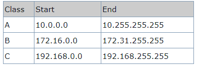
5. Explain NAT?
To access the Internet, one public IP address is needed, but we can use a private IP address in our private network.
Network Address Translation (NAT) is a process in which one or more local IP address is translated into one or more Global IP address and vice versa to provide Internet access to the local hosts.
It also does translation of port numbers that is masks the port number of the host with another port number, in the packet that will be routed to the destination. It then makes the corresponding entries of IP address and port number in the NAT table. NAT generally operates on router or firewall.
Network Address Translation (NAT) working –
Generally, the border router is configured for NAT that is the router which has one interface in local (inside) network and one interface in the global (outside) network. When a packet traverse outside the local (inside) network, then NAT converts that local (private) IP address to a global (public) IP address. When a packet enters the local network, the global (public) IP address is converted to a local (private) IP address.
If NAT run out of addresses that is no address is left in the pool configured then the packets will be dropped and an Internet Control Message Protocol (ICMP) host unreachable packet to the destination is sent.
6. Explain the inside and outside classes?
Inside refers to the addresses which must be translated. Outside refers to the addresses which are not in control of an organisation. These are the network Addresses in which the translation of the addresses will be done.

- Inside local address – An IP address that is assigned to a host on the Inside (local) network. The address is probably not IP address assigned by the service provider that is these are private IP address. This is the inside host seen from the inside network.
- Inside global address – IP address that represents one or more inside local IP addresses to the outside world. This is the inside host as seen from the outside network.
- Outside local address – This is the actual IP address of the destination host in the local network after translation.
- Outside global address – This is the outside host as seen from the outside network. It is the IP address of the outside destination host before translation.
7. Explain subnetting and supernetting?
Subnetting is the procedure to divide the network into sub-networks or small networks.
Supernetting:
Supernetting is the procedure of combine the small networks into larger space. In subnetting the Network addresses’ bits are increased. The Host addresses’ bits are increased.
Subnetting is implemented via Variable-length subnet masking, While super netting is implemented via Classless interdomain routing.

Difference between Subnetting and Super netting:
Sl No | Subnetting | Supernetting |
1 | Subnetting is the procedure to divide the network into sub networks | It is the procedure of combining the small networks |
2 | Network addresses’ bits are increased | Host addresses bits are increased |
3 | The mask bits are moved towards the right | The mask bits are moved towards the left |
4 | Variable length subnet masking | Classless interdomain routing |
5 | Address depletion is reduced or removed | Simplify routing process |
8. Explain delivery?
The network layer supervises the handling of the packets by the underlying physical networks.
This handling is called as delivery of a packet.
The delivery of a packet to its final destination is accomplished using two different methods of delivery: direct and indirect
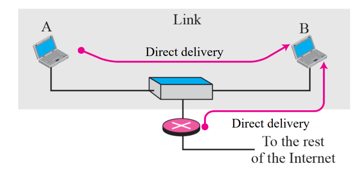
Direct Delivery:
The final destination of the packet is a host connected to the same physical network as the deliverer.
- Source and destination of the packet are located on the same physical network
- Delivery between last router and the destination host
- Extract the network address of the destination and compare this address with the addresses of the networks to which it is connected If a match is found, the delivery is direct
- The sender uses the destination IP address to find the destination physical address
Indirect Delivery:
The destination host in not on the same network as the delivery
- The packet goes from router to router until it reaches the one connected to the same physical network
- The sender uses the destination IP address and a routing table to find IP address of the next router

10.Explain forwarding?
- Forwarding means to place the packet in its route to its destination Since the Internet is made of a combination of links, forwarding means to deliver the packet to the next hop
- Although IP protocol was originally designed as a connectionless protocol, today the tendency is to use IP as a connection-oriented protocol based on the label attached to an IP datagram
Forwarding based on destination address
- Next-hop
- Network- Specific Method
- Host-Specific Method
- Default Method
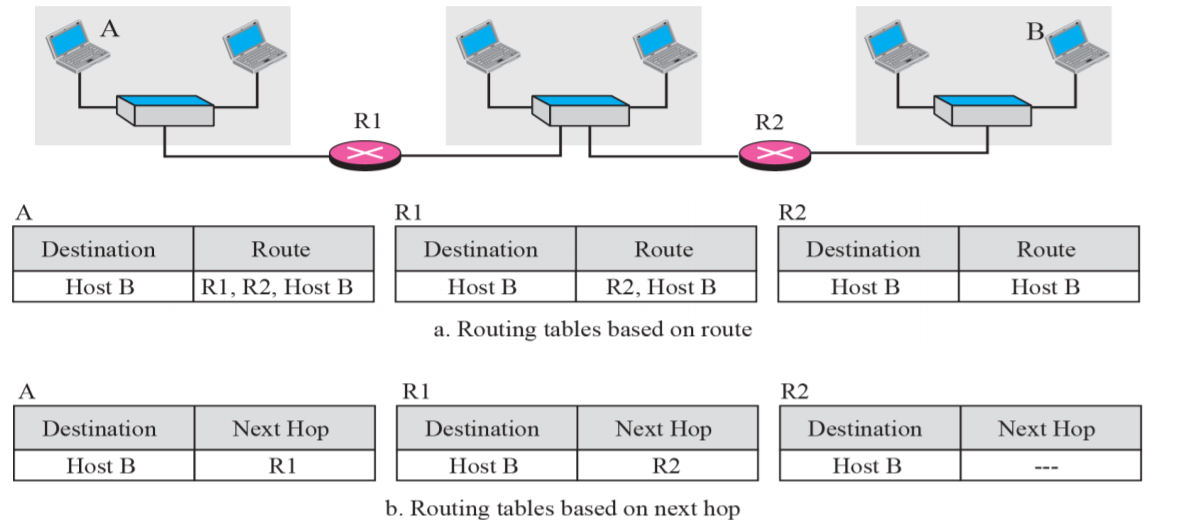
Next-Hop Method
One technique to reduce the contents of a routing table
The routing table holds only the address of the next hop instead of information about the complete route.
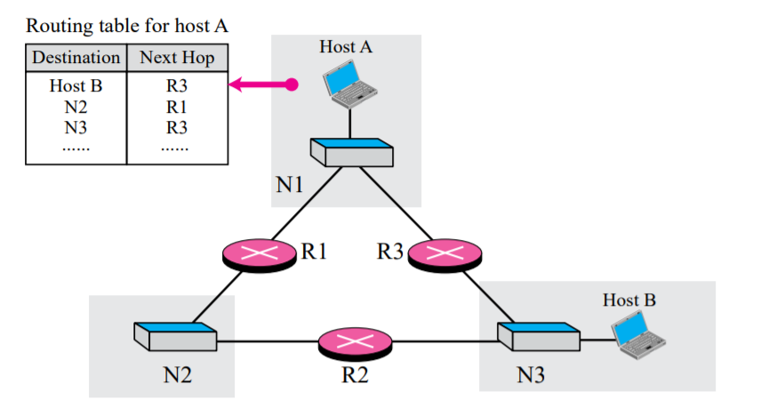
Network Specific Method
Reduce the routing table and simplify the searching process
The routing table has only one entry that defines the address of the destination network itself

Host Specific Method
- The Destination host address is given in the routing table
- Inverse of network-specific method
- When administrator wants to have more control
Default Method
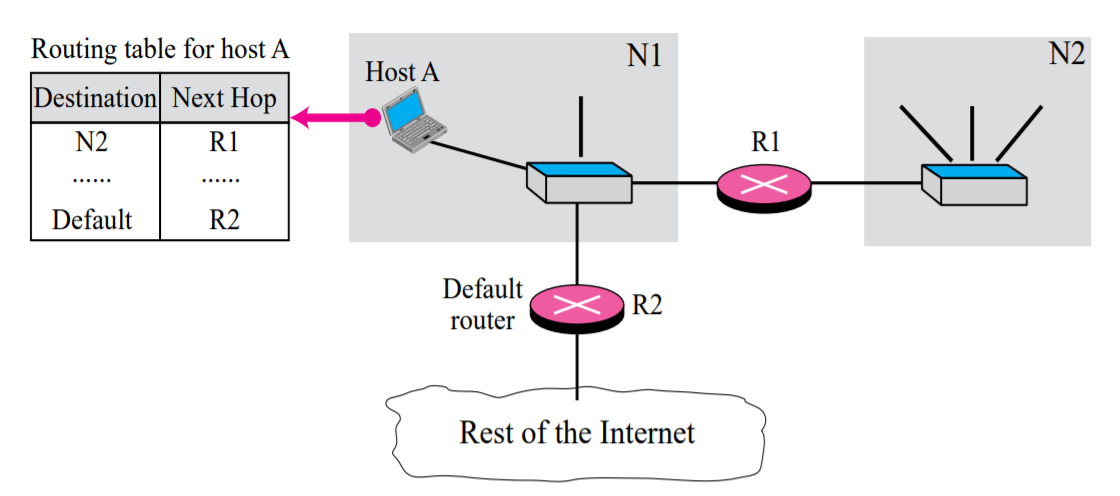
Instead of listing all networks in the entire Internet host can just have one entry called the default
11. Explain the structure of router?
Routers are the building blocks of wide area networks. Figure shows an abstract model of a router as a layer 3 switch. The Packets arrive at n input ports and are routed out from n output ports. The system consists of four main parts:
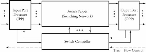 Overview of typical router Input Port Processor (IPP)
Input and output port processors act as interfaces to switch fabric which are commercially implemented together in router line cards, which contain some of the task of the physical and data link layers. An input port processor (IPP) typically consists of several main modules, as shown in Figure. These modules are packet fragmentation, main buffer , multicast process , routing table , packet encapsulator and a comprehensive QoS . Overview of a typical IPP in routers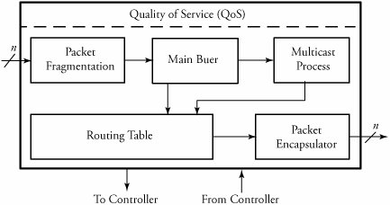
Switch Fabric
In the switch fabric of a router, packets are routed from input ports to the desired output ports. A packet can also be multicast to more than one output. Figure shows an abstract model of a virtual circuit switching router, another example of switching systems. This model can work for ATM technology: Cells (packets) arrive at n input ports and are routed out from n output ports. When a cell carrying VCI b arrives from a given link i , the cell's VCI is used to index a virtual-circuit translation table (VXT) in the corresponding input port processor to identify the output link address j and a new VCI c . In the switching network, cells are routed to the desired outputs. As shown in Figure a cell can also be multicast to more than one output. Finally, in output port processors, cells are buffered; in some switch architectures, cells are resequenced in order to avoid mis ordering. Interaction between an IPP and its switch fabric in a virtual-circuit switching router
Switch Controller
The controller part of a switching system makes decisions leading to the transmission of packets to the requested output(s). The details of the controller are illustrated in Figure. The controller receives packets from an IPP, but only the headers of packets are processed in the controller. In the controller, the header decoder first converts the control information of an arriving packet into an initial requested output vector. This bit vector carries the information pertaining to the replication of a packet so that any bit of 1 represents a request for one of the corresponding switch outputs. Overview of a switching system controller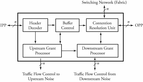
Output Port Processors (OPP)
Implementing output port processors in switches includes parallel-to-serial multiplexing, main buffer, local packet resequencer, global packet resequencer, error checker, and packet reassembler, as shown in Figure . Similar to IPP, OPP also contributes to congestion control. Parallel-to-serial multiplexing converts the parallel-packet format into serial packet format. Overview of a typical OPP in routers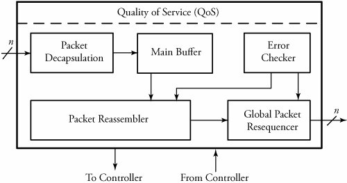
|
12. Explain IPv4?
Datagrams
IPv4 is a connectionless protocol for a packet- switching network that uses the datagram approach. This means that each datagram is handled independently, and each datagram can follow a different route to the destination.
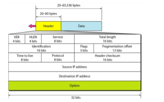
Packets in the IPv4 layer are called datagrams. A datagram is a variable-length packet consisting of two parts: header and data. The header is 20 to 60 bytes in length and contains information essential to routing.
- Version (VER): This 4-bit field defines the version of the IPv4 protocol. Currently, the version is 4. However, version 6 (or IPng) may totally replace version 4 in the future.
- Header length (HLEN): This 4-bit field defines the total length of the datagram header in 4-byte words. This field is needed because the length of the header is variable (between 20 and 60 bytes).
- Services: IETF has changed the interpretation and name of this 8-bit field. This field, previously called service type, is now called differentiated services.
- Type of service: Low Delay, High Throughput, Reliability (8 bits)
- Total Length: Length of header + Data (16 bits), which has a minimum value 20 bytes and the maximum is 65,535 bytes
- Identification: Unique Packet Id for identifying the group of fragments of a single IP datagram (16 bits)
- Flags: 3 flags of 1 bit each: reserved bit (must be zero), do not fragment flag, more fragments flag (same order)
- Fragment Offset: Specified in terms of number of 8 bytes, which has the maximum value of 65,528 bytes
- Time to live: Datagram’s lifetime (8 bits), It prevents the datagram to loop in the network
- Protocol: Name of the protocol to which the data is to be passed (8 bits)
- Header Checksum: 16 bits header checksum for checking errors in the datagram header
- Source IP address: 32 bits IP address of the sender
- Destination IP address: 32 bits IP address of the receiver
- Option: Optional information such as source route. Due to the presence of options, the size of the datagram header can be of variable length (20 bytes to 60 bytes).
Fragmentation
Different Networks have different maximum transmission unit (MTU). When one network wants to transmit datagrams to a network with a smaller MTU, the routers on path may fragment and reassemble datagrams.
When a packet is received at the router, destination address is examined and MTU is determined.
If size of the packet is bigger than the MTU, and the ‘Do not Fragment (DF)’ bit is set to 0 in header, then the packet is fragmented into parts and sent one by one.
The maximum size of each fragment is the MTU minus the IP header size (Minimum 20 bytes and Maximum 60 bytes).
Each fragment is converted to a packet and the following changes happen in the datagram header:
- The total length field is changed to the size of the fragment.
- The More Fragment bit (MF bit) is set for all the fragment packets except the last one.
- The fragment offset field is set, based on the number of fragment that is being set and the MTU.
- Header Checksum is re-calculated.
Example: For a data packet of 4000 bytes and MTU of 1500 bytes, we have actual data of 3980 bytes that is to be transmitted and 1480 bytes is the maximum data size that is permissible to be sent. So, there would be 3 fragments:
For the first fragment, data size = 1480 bytes, offset = 0 and MF flag = 1
For the second fragment, data size = 1480 bytes, offset = 1480 and MF flag = 1
For the third fragment, data size = 1020 bytes, offset = 2960 and MF flag = 0
Options
ILNP for IPv4 (ILNPv4) is merely a different instantiation of the ILNP architecture, so it retains the crisp distinction between the Locator and the Identifier. As with ILNP for IPv6 (ILNPv6), when ILNPv4 is used for a network-layer session, the upper-layer protocols
Checksum
Header Checksum is a 16- bit field in IPv4 packet header. It is used to check the packet for its quality.
It must be calculated on each hop(router) and if it does not match then packet has to be discarded.
Most of the network relies on higher layer checksum like UDP and TCP has their own header checksum.
As TTL value decrements at each hop hence header checksum must be calculated on each hop.
13. Explain IPv6 Addressing?
Notations
IPv6 addresses are so much larger than IPv4 addresses that even using dotted decimal notation becomes problematic. To use this notation, we would split the 128 bits into 16 octets and represent each with a decimal number from 0 to 255. However, we would end up not with 4 of these numbers, but 16.
A typical IPv6 address in this notation would appear as follows:
128.91.45.157.220.40.0.0.0.0.252.87.212.200.31.255

Address Space
The type of an IPv6 address is identified by the high-order bits of the address as shown in Table
Address type | Binary Prefix | IPv6 notation |
Unspecified | 00..0(128 bits) | ::/128 |
Loopback | 00…1(128 bits) | ::1/128 |
Unique local unicast | 111110 | FC00::/7 |
Multicast | 11111111 | FF00::/8 |
Link-local unicast | 1111111010 | FE80::/10 |
Global unicast aggregatable | (everything else) |
|
Anycast addresses are taken from the unicast address spaces and are not syntactically distinguishable from unicast addresses.
Anycast is described as a cross between unicast and multicast.
Like unicast, a packet sent to an anycast address is delivered to one and only one of those nodes. The exact node to which it is delivered is based on the IP routing tables in the network.
Packet Format
An IPv6 packet has three parts: an IPv6 basic header, one or more IPv6 extension headers, and an upper-layer protocol data unit (PDU).
An upper-layer PDU is composed of upper-layer protocol header and its payload which maybe an ICMP v6 packet, a TCP packet, or UDP packet.
IPv6 Basic Header
An IPv6 basic header is fixed as 40 bytes long and has eight fields. Each IPv6 packet must have an IPv6 basic header that provides basic packet forwarding information in which all devices parse on the forwarding path.
IPv6 basic header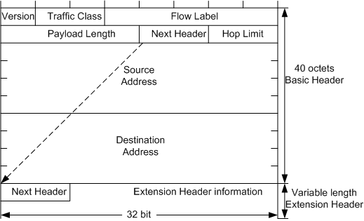
An IPv6 basic header contains the following fields:
- Version: 4 bits long. In IPv6, the value of the Version field is set to 6.
- Traffic Class: It is 8 bits long. This field indicates the class or priority of an IPv6 packet. The Traffic Class field is like TOS field in an IPv4 packet and mainly used in QoS control.
- Flow Label: It is 20 bits long. This field was added in IPv6 to differentiate traffic. A flow label and source IP address identify a data flow.
- Payload Length: 16 bits long. This field indicates the length of the IPv6 payload in bytes. The payload is the part of the IPv6 packet following the IPv6 basic header, including the extension header and upper-layer PDU. This field has a maximum value of 65535.
- Next Header: 8 bits long. This field identifies the type of the first extension header that follows the IPv6 basic header or the protocol type in the upper-layer PDU.
- Hop Limit: 8 bits long. This field is like the Time to Live field in an IPv4 packet, defining the maximum number of hops that an IP packet can pass through. Each device that forwards the packet decrements the field value by 1.
- Source Address: 128 bits long. This field indicates the address of the packet originator.
- Destination Address: 128 bits long. This field indicates the address of the packet recipient.
Ipv6 Extension Header
To improve packet processing efficiency, IPv6 uses extension headers to replace the Options field in the IPv4 header. Extension headers are placed between the IPv6 basic header and upper-layer PDU. An IPv6 packet may carry zero or more extension headers. The sender of a packet adds one or more extension headers to the packet only when the sender requests the destination device or other devices to perform special handling.
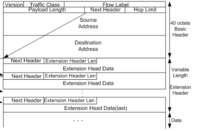
An IPv6 extension header contains the following fields:
- Next Header: 8 bits long. Like the Next Header field in the IPv6 basic header, indicating the type of the next extension header (if any) or the upper-layer protocol type.
- Extension Header Len: 8 bits long. This indicates the extension header length excluding the Next Header field.
- Extension Head Data: Variable length. This includes a series of options and the padding field.
14. Explain transition from IPv4 to IPv6 ?
When we want to send a request from an IPv4 address to IPv6 address it is not possible because IPv4 and IPv6 transition are not compatible. Hence as a solution to these problems we use some technologies.
The technologies are:
Dual Stack Routers, Tunnelling, and NAT Protocol Translation.
Dual Stack Routers:
In dual stack router a router’s interface is attached with Ipv4 and IPv6 addresses configured and used in order to obtain transition from IPv4 to IPv6.
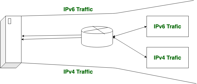
In the above diagram, A given server with both IPv4 and IPv6 address configured can communicate with all hosts of IPv4 and IPv6 via dual stack router (DSR). The dual stack router (DSR) gives the path for all the hosts to communicate with server without changing their IP addresses.
Tunnelling:
Tunnelling is used as a medium to communicate the transit network with the different ip versions.

In the above diagram different IP versions such as IPv4 and IPv6 are present. The IPv4 networks communicate with the transit or intermediate network on IPv6 with the help of Tunnel.
It’s also possible that the IPv6 network can also communicate with IPv4 networks with the help of Tunnel.
NAT Protocol Translation:
With the help of NAT Protocol Translation technique IPv4 and IPv6 networks can communicate with each other which do not understand the address of different IP version.
Generally, an IP version doesn’t understand the address of different IP version, for the solution of this problem we use NAT-PT device which remove the header of first (sender) IP version address and add the second (receiver) IP version address so that the Receiver IP version address understand that the request is send by the same IP version, and its vice-versa is also possible.

In above diagram, an IPv4 address communicate with the IPv6 address via NAT-PT device to communicate easily. In this situation IPv6 address understand that the request is send by the same IP version (IPv6) and it respond.