Unit V
Network Layer : Routing Protocols
- Explain metrics?
Routing protocol algorithms use metrics which are numerical values that are associated with specific routes.
These values are used to prioritize the prefer routes by the routing protocol from the most preferred to the least preferred.
The route with the lowest metric is typically the route with least cost or best route to the destination network. This route will be placed into the routing table and be used to forward packets to the destination network.
Different routing algorithms use different variables to compute the route metric. Some routing algorithms use only a single variable, while other advanced routing protocols may use more than one variable to determine the metric for a particular route.
The different routing protocol metrics may be based on one or more of the following:
- Bandwidth
- Cost
- Delay
- Load
- Path Length
- Reliability
2. Explain static and dynamic routing?
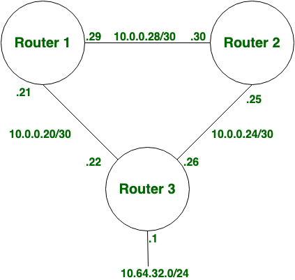
Static Routing:
Static Routing is also known as non-adaptive routing which does not change routing table unless the network administrator changes or modify them manually. Static routing does not use complex routing algorithms and provides high or more security than dynamic routing.
Dynamic Routing:
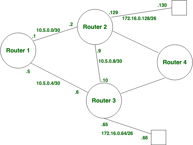
Dynamic routing known as adaptive routing change routing table according to the change in topology. Dynamic routing uses complex routing algorithms, and it does not provide high security like static routing.
When the network change(topology) occurs, it sends the message to router to ensure that changes then the routes are recalculated for sending updated routing information.
3.Explain Routing Table?
A routing table is a set of rules viewed in table format which is used to determine where data packets are traveling over an Internet Protocol (IP) network which will be directed.
All IP-enabled devices including routers and switches use routing tables.
Consider the following table:
Destination | Subnet mask | Interface |
128.75.43.0 | 255.255.255.0 | Eth0 |
128.75.43.0 | 255.255.255.128 | Eth1 |
192.12.17.5 | 255.255.255.255 | Eth3 |
Default | Eth2 |
|
The entry corresponding the default gateway configuration is a network destination of 0.0.0.0 with a network mask (netmask) of 0.0.0.0.
The Subnet Mask of default route is always 255.255.255.255.
4.Explain the entries in routing table?
A routing table contains the information necessary to forward a packet along the best path toward its destination. Each packet contains information about its origin and destination.
Routing Table provides the device with instructions for sending the packet to the next hop on its route across the network.
Each entry in the routing table consists of the following entries:
- Network ID:
The network ID or destination corresponding to the route. - Subnet Mask:
The mask that is used to match a destination IP address to the network ID. - Next Hop:
The IP address to which the packet is forwarded - Outgoing Interface:
Outgoing interface the packet should go out to reach the destination network. - Metric:
A common use of the metric is to indicate the minimum number of hops (routers crossed) to the network ID.
5.Explain Distance Vector Routing ?
A distance-vector routing (DVR) protocol requires that the router inform its neighbours that topology changes periodically.
Distance Vector Algorithm –
- A router transmits its distance vector to each of its neighbours in a routing packet.
- Each router receives and saves the most recently received distance vector from each of its neighbours.
- A router recalculates its distance vector when:
- It receives a distance vector from a neighbour containing different information than before.
- It discovers that a link to a neighbour has gone down.
6. What is Link State Routing?
While distance vector routers use a distributed algorithm to compute their routing tables, link-state routing uses link-state routers to exchange messages that allow each router to learn the entire network topology.
Based on this topology each router is able to compute its routing table by using a shortest path computation.
Features of link state routing protocols –
- Link state packet – A small packet that contains routing information.
- Link state database – A collection information gathered from link state packet.
- Shortest path first algorithm (Dijkstra algorithm) – A calculation performed on the database results into shortest path
- Routing table – A list of known paths and interfaces.
Consider 3-routers X, Y and Z as shown in figure. Each router has their routing table. Every routing table will contain distance to the destination nodes.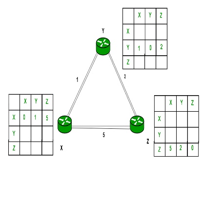
Consider router X , X will share it routing table to neighbours and neighbours will share it routing table to it to X and distance from node X to destination will be calculated using bellmen- ford equation.
Dx(y) = min{C(x,v) + Dv(y)} for each node y ∈ N
We can see that distance will be less going from X to Z when Y is intermediate node (hop) so that it updates the routing table X.
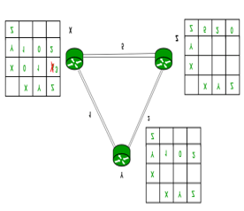
Similarly, for Z also
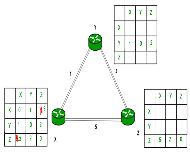
Finally, the routing table for all –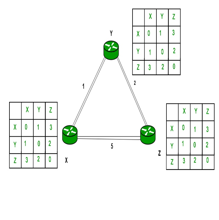
7. Explain Path vector Routing
- Path Vector Routing is a routing algorithm in unicast routing protocol of network layer useful for interdomain routing. The principle of path vector routing is like distance vector routing.
- It assumes that there is one node in each autonomous system and acts on behalf of the entire autonomous system called Speaker node.
- The speaker node in AS creates a routing cable and advertises to the speaker node in the neighbouring ASs.
- A speaker node advertises the path, not the metrics of the nodes, in its autonomous system or other autonomous system.
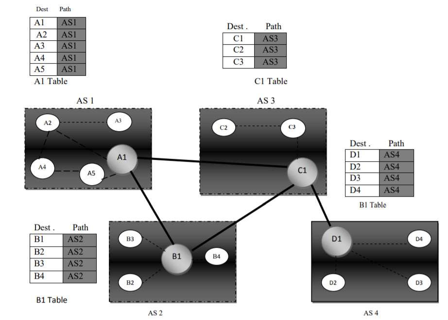
It is the initial table for each speaker node in a system made four ASs.
Here Node A1 is the speaker node for AS1, B1 for AS2, C1 for AS3 and D1 for AS4. Node A1 creates an initial table that shows A1 to A5 and these are located in AS1, it can be reached through it Dest .
Path C1 AS3 C2 AS3 C3 AS3 Dest .
Path D1 AS4 D2 AS4 D3 AS4 D4 AS4 Dest .
Path B1 AS2 B2 AS2 B3 AS2 B4 AS2 Dest
Path A2 2 A3 A4 A5 A1 C2 2 C3 C1 B1
Table B1 Table AS 2 AS 4 B2 2 D2 2 B3 2 B4 2 D3 2 D4 2 B1 D1 Initial routing tables in path vector routine A speaker in an autonomous system shares its table with immediate neighbours here Node A1 share its table with nodes B1 and C1 , Node C1 share its table with nodes A1,B1 and D1 , Node B1 share its table with nodes A1 and C1 , Node D1 share its table with node C1 If router A1 receives a packet for nodes A3 , it knows that the path is in AS1,but if it receives a packet for D1,it knows that the packet should go from AS1,to AS2 and then to AS3 ,then the routing table shows that path completely on the other hand if the node D1 in AS4 receives a packet for node A2,it knows it should go through AS4,AS3,and AS1.
8. Explain Optimality Principle?
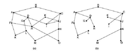
Optimality principle states that if router J is on the optimal path from router I to router K then the optimal path from router J to K also falls along the same route. To view this call the part of the route from I to Jr1 and the rest of the route r2. If a route better than r2 existed from J to K it can be concatenated with r1 to improve the route from I to K contradicting our statement that r1r2 is optimal.
As a direct sequence one can see that the set of optimal routes from all sources to given destination from tree rooted at the destination . Such a tree is called sink tree as shown in figure where the distance metric is the number of hops.
9. Intra and Inter Domain Routing
Intra domain is any protocol in which Routing algorithm works only within domains while Inter domain is the Routing algorithm which works within and between domains.
Sr. No. | Key | InterDomain Routing | IntraDomain Routing |
1 | Definition | InterDomain Routing as name suggests is the protocol in which Routing algorithm works within and between domains. | On other hand IntraDomain as name suggests is a protocol in which Routing algorithm works only within the domains. |
2 | Information Required | In case of InterDomain the interaction is between different domains so information of components of other domains is also required. | On other hand as IntraDomain Routing has to interact within the domain so only information of different components within the domain is required. |
3 | Protocols Used | In InterDomain Routing Interior-gateway protocols such as RIP(resource information protocol) and OSPF(open shortest path first) are being used. | While On other Exterior-gateway protocols such as BGP(Border Gateway Protocol) are being get used in case of IntraDomain Routing. |
4 | Prerequisite | For InterDomain Routing internet within the domain and in domain with which the interaction is going on should be connected and available. | On other hand for IntraDomain Routing internet within the domain should be connected and available during the transmission. |
5 | Complex and Independent | InterDomain Routing is more complex and more dependent as compared to that of IntraDomain Routing. | On other hand as mentioned in above points the IntraDomain Routing is less complex and less interdependent as compared to that of InterDomain Routing. |
9. Explain shortest path routing?
In shortest path routing the topology communication network is represented by using a directed weighted graph.
The nodes in the graph represent switching elements and directed arcs represent communication links between switching elements.
Each arc has a weight that represents the cost of sending a packet between two nodes in a particular direction. This cost is of positive value that can inculcate factors such as delay, throughput, error rate , monetary cost etc.
A path between two nodes may go through several intermediary nodes and arc. The objective in shortest path routing is to find a path between two nodes that has smallest total cost of a path is the sum of the arc costs in that path.
10. What is flooding?
Flooding is the static routing algorithm. In this algorithm, every incoming packet is sent on all outgoing lines except the line on which it has arrived.
One major problem of this algorithm is that it generates large number of duplicate packets on the network.
Several measures are taken to stop the duplication of packets.
These are:
1. One solution is to include a hop counter in the header of each packet. This counter is decremented at each hop along the path. When this counter reaches zero the packet is discarded.
2. Another technique is to keep the track of the packets that have been flooded to avoid sending them a second time. For this the source router put a sequence number in each packet it receives from its hosts.
3. Another solution is to use selective flooding. In selective flooding the routers do not send every incoming packet out on every output line. Instead packet is sent only on those lines which are approximately going in the right direction.
11. Explain distance vector routing?
Distance vector routing is a dynamic routing algorithm.
It works in the following steps-
Step 1:
Each router prepares its routing table. Each router present in the network knows about:
- All the routers present in the network
- Distance to its neighbouring routers
Step 2:
- Each router exchanges its distance vector with its neighbouring routers.
- Each router prepares a new routing table using the distance vectors it has obtained from its neighbours.
- This step is repeated for (n-2) times if there are n routers in the network.
- After this, routing tables converge / become stable.
Consider-
- There is a network consisting of 4 routers.
- The weights are mentioned on the edges.
- Weights could be distances or costs or delays.
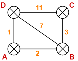
Step-01:
Each router prepares its routing table using its local knowledge.
Routing table prepared by each router is shown below-
At Router A
Destination | Distance | Next Hop |
A | 0 | A |
B | 2 | B |
C | ∞ | - |
D | 1 | D |
At Router B –
Destination | Distance | Next Hop |
A | 2 | A |
B | 0 | B |
C | 3 | C |
D | 7 | D |
At Router C-
Destination | Distance | Next Hop |
A | 2 | A |
B | 0 | B |
C | 3 | C |
D | 7 | D |
At Router D
Destination | Distance | Next Hop |
A | 1 | A |
B | 7 | B |
C | 11 | C |
D | 0 | D |
Step-02:
- Each router exchanges its distance vector obtained in Step-01 with its neighbours.
- After exchanging the distance vectors, each router prepares a new routing table.
At Router A-
- Router A receives distance vectors from its neighbours B and D.
- Router A prepares a new routing table as-
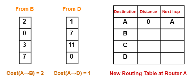
- Cost of reaching destination B from router A = min { 2+0 , 1+7 } = 2 via B.
- Cost of reaching destination C from router A = min { 2+3 , 1+11 } = 5 via B.
- Cost of reaching destination D from router A = min { 2+7 , 1+0 } = 1 via D.
For Destination B
- Router A can reach the destination router B via its neighbour B or neighbour D.
- It chooses the path which gives the minimum cost.
- Cost of reaching router B from router A via neighbour B = Cost (A→B) + Cost (B→B)= 2 + 0 = 2
- Cost of reaching router B from router A via neighbour D = Cost (A→D) + Cost (D→B) = 1 + 7 = 8
- Since the cost is minimum via neighbour B, so router A chooses the path via B.
- It creates an entry (2, B) for destination B in its new routing table.
- Similarly, we calculate the shortest path distance to each destination router at every router.
Thus, the new routing table at router A is-
Destination | Distance | Next Hop |
A | 0 | A |
B | 2 | B |
C | 5 | B |
D | 1 | D |
At Router B-
- Router B receives distance vectors from its neighbours A, C and D.
- Router B prepares a new routing table as-
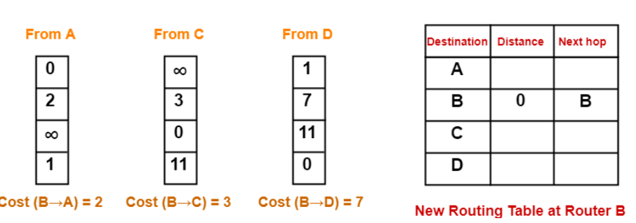
- Cost of reaching destination A from router B = min { 2+0 , 3+∞ , 7+1 } = 2 via A.
- Cost of reaching destination C from router B = min { 2+∞ , 3+0 , 7+11 } = 3 via C.
- Cost of reaching destination D from router B = min { 2+1 , 3+11 , 7+0 } = 3 via A.
Thus, the new routing table at router B is-
Destination | Distance | Next Hop |
A | 2 | A |
B | 0 | B |
C | 3 | C |
D | 3 | A |
At Router C-
- Router C receives distance vectors from its neighbours B and D.
- Router C prepares a new routing table as-
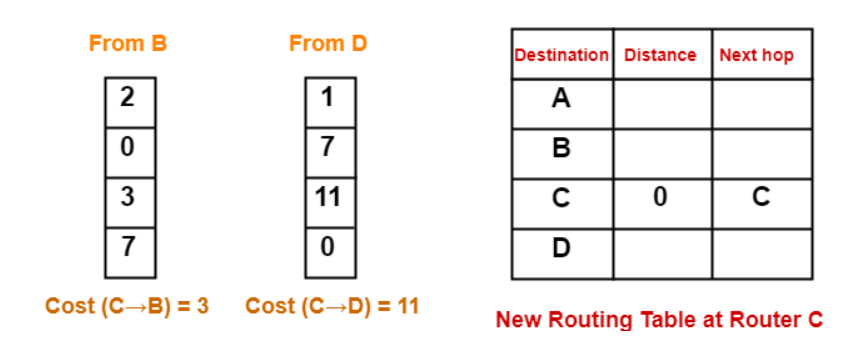
- Cost of reaching destination A from router C = min { 3+2 , 11+1 } = 5 via B.
- Cost of reaching destination B from router C = min { 3+0 , 11+7 } = 3 via B.
- Cost of reaching destination D from router C = min { 3+7 , 11+0 } = 10 via B.
Thus, the new routing table at router C is-
Destination | Distance | Next Hop |
A | 5 | B |
B | 3 | B |
C | 0 | C |
D | 10 | B |
At Router D-
- Router D receives distance vectors from its neighbours A, B and C.
- Router D prepares a new routing table as-

- Cost of reaching destination A from router D = min { 1+0 , 7+2 , 11+∞ } = 1 via A.
- Cost of reaching destination B from router D = min { 1+2 , 7+0 , 11+3 } = 3 via A.
- Cost of reaching destination C from router D = min { 1+∞ , 7+3 , 11+0 } = 10 via B.
Thus, the new routing table at router D is-
Destination | Distance | Next Hop |
A | 1 | A |
B | 3 | A |
C | 10 | B |
D | 0 | D |
Step-03:
- Each router exchanges its distance vector obtained in Step-02 with its neighbouring routers.
- After exchanging the distance vectors, each router prepares a new routing table.
This is shown below-
At Router A-
Router A receives distance vectors from its neighbors B and D.
- Router A prepares a new routing table as-
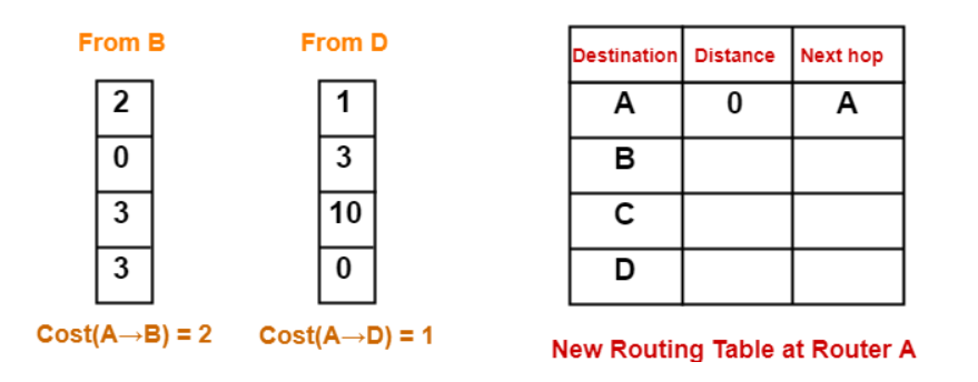
- Cost of reaching destination B from router A = min { 2+0 , 1+3 } = 2 via B.
- Cost of reaching destination C from router A = min { 2+3 , 1+10 } = 5 via B.
- Cost of reaching destination D from router A = min { 2+3 , 1+0 } = 1 via D.
Thus, the new routing table at router A is-
Destination | Distance | Next Hop |
A | 0 | A |
B | 2 | B |
C | 5 | B |
D | 1 | D |
At Router B-
- Router B receives distance vectors from its neighbours A, C and D.
- Router B prepares a new routing table as-
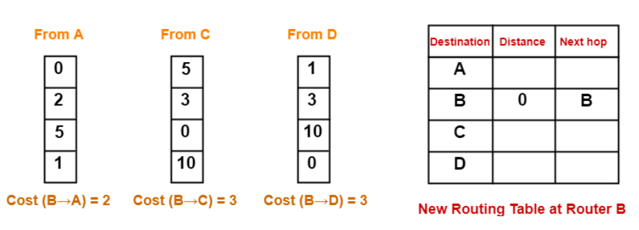
- Cost of reaching destination A from router B = min { 2+0 , 3+5 , 3+1 } = 2 via A.
- Cost of reaching destination C from router B = min { 2+5 , 3+0 , 3+10 } = 3 via C.
- Cost of reaching destination D from router B = min { 2+1 , 3+10 , 3+0 } = 3 via A.
Thus, the new routing table at router B is-
Destination | Distance | Next Hop |
A | 2 | A |
B | 0 | B |
C | 3 | C |
D | 3 | A |
At Router C-
- Router C receives distance vectors from its neighbours B and D.
- Router C prepares a new routing table as-
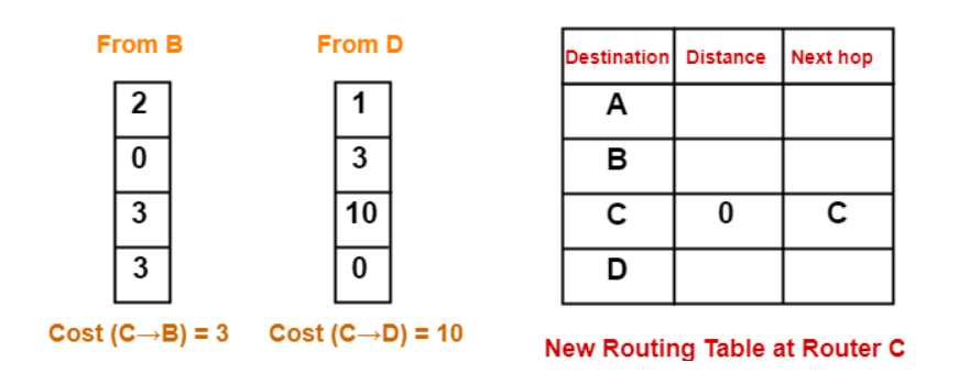
- Cost of reaching destination A from router C = min { 3+2 , 10+1 } = 5 via B.
- Cost of reaching destination B from router C = min { 3+0 , 10+3 } = 3 via B.
- Cost of reaching destination D from router C = min { 3+3 , 10+0 } = 6 via B.
Thus, the new routing table at router C is-
Destination | Distance | Next Hop |
A | 5 | B |
B | 3 | B |
C | 0 | C |
D | 6 | B |
At Router D-
- Router D receives distance vectors from its neighbours A, B and C.
- Router D prepares a new routing table as-
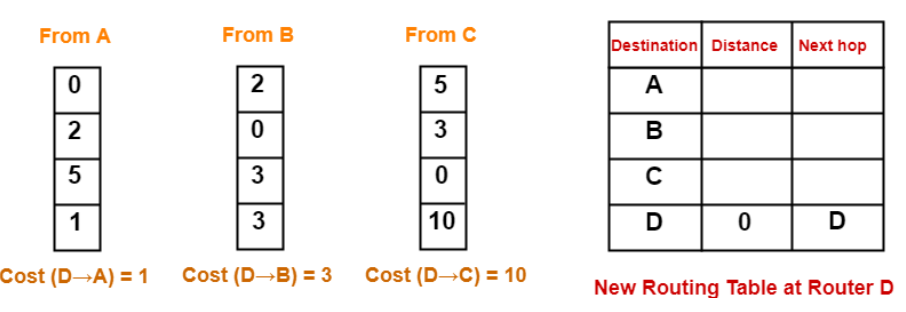
- Cost of reaching destination A from router D = min { 1+0 , 3+2 , 10+5 } = 1 via A.
- Cost of reaching destination B from router D = min { 1+2 , 3+0 , 10+3 } = 3 via A.
- Cost of reaching destination C from router D = min { 1+5 , 3+3 , 10+0 } = 6 via A.
Thus, the new routing table at router D is-
Destination | Distance | Next Hop |
A | 1 | A |
B | 3 | A |
C | 6 | A |
D | 0 | D |
These will be the final routing tables at each router.
12. Explain link state routing?
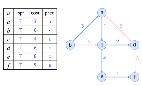
In link-state routing, each node:
• Floods the network with the state (up, down) of its links
• Uses Dijkstra’s Shortest Path First (SPF) algorithm to compute a shortest-path tree
Dijkstra’s SPF Example (init)
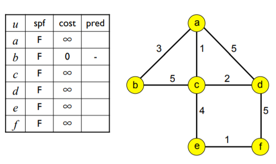
(v=s=b)
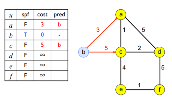
(v=a)
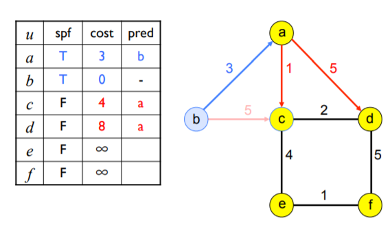
(v=c)
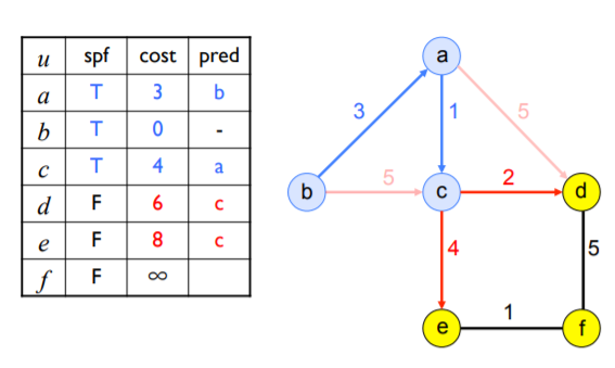
(v=d)
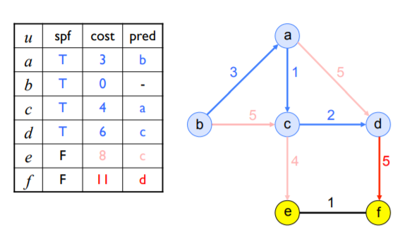
v=e
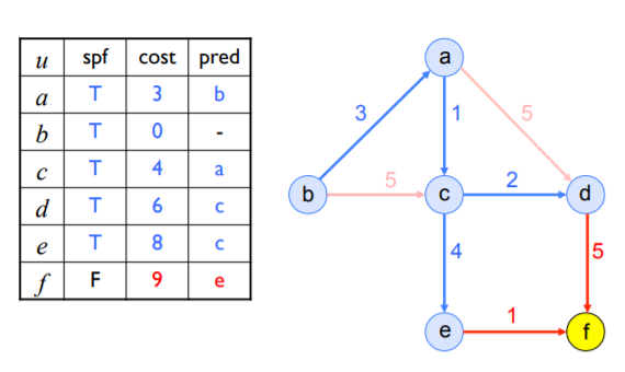
(v=f)
13. Explain interior gateway routing?
- Interior Gateway Protocol or IGRP is a distance vector routing protocol.
- IGRP was designed to build on the foundations laid down on RIP to function more effectively within larger connected networks and removed the 15 hop cap that was placed on RIP.
- IGRP uses metrics such as bandwidth, delay, reliability, and load to compare the viability of routes within the network. However, only bandwidth and delay are used under IGRP’s default settings.
- IGRP is ideal for larger networks because it broadcasts updates every 90 seconds and has a maximum hop count of 255. This allows it to sustain larger networks than a protocol like RIP.
- IGRP is also widely used because it is resistant to routing loops because it updates itself automatically when route changes occur within the network.