UNIT 5
Processor Instructions &Processor Enhancements
- Explain in detail Instruction: elements of machine instruction
Machine Instructions are commands or programs written in machine code of a machine (computer) that it can recognize and execute.
- A machine instruction consists of several bytes in memory that tells the processor to perform one machine operation.
- The processor looks at machine instructions in main memory one after another, and performs one machine operation for each machine instruction.
- The collection of machine instructions in main memory is called a machine language program.
Machine code or machine language is a set of instructions executed directly by a computer’s central processing unit (CPU). Each instruction performs a very specific task, such as a load, a jump, or an ALU operation on a unit of data in a CPU register or memory. Every program directly executed by a CPU is made up of a series of such instructions.
The general format of a machine instruction is
[Label:] Mnemonic [Operand, Operand] [; Comments] |
- Brackets indicate that a field is optional
- Label is an identifier that is assigned the address of the first byte of the instruction in which it appears. It must be followed by “:”
- Inclusion of spaces is arbitrary, except that at least one space must be inserted; no space would lead to an ambiguity.
- Comment field begins with a semicolon “ ; ”
Example:
Here: MOV R5,#25H ;load 25H into R5 |
Machine instructions used in 8086 microprocessor
1. Data transfer instructions– move, load exchange, input, output.
- MOV :Move byte or word to register or memory .
- IN, OUT: Input byte or word from port, output word to port.
- LEA: Load effective address
- LDS, LES Load pointer using data segment, extra segment .
- PUSH, POP: Push word onto stack, pop word off stack.
- XCHG: Exchange byte or word.
- XLAT: Translate byte using look-up table.
2. Arithmetic instructions – add, subtract, increment, decrement, convert byte/word and compare.
- ADD, SUB: Add, subtract byte or word
- ADC, SBB :Add, subtract byte or word and carry (borrow).
- INC, DEC: Increment, decrement byte or word.
- NEG: Negate byte or word (two’s complement).
- CMP: Compare byte or word (subtract without storing).
- MUL, DIV: Multiply, divide byte or word (unsigned).
- IMUL, IDIV: Integer multiply, divide byte or word (signed)
- CBW, CWD: Convert byte to word, word to double word
- AAA, AAS, AAM,AAD: ASCII adjust for add, sub, mul, div .
- DAA, DAS: Decimal adjust for addition, subtraction (BCD numbers)
3. Logic instructions – AND, OR, exclusive OR, shift/rotate and test
- NOT : Logical NOT of byte or word (one’s complement)
- AND: Logical AND of byte or word
- OR: Logical OR of byte or word.
- XOR: Logical exclusive-OR of byte or word
- TEST: Test byte or word (AND without storing).
- SHL, SHR: Logical Shift rotate instruction shift left, right byte or word? by 1or CL
- SAL, SAR: Arithmetic shift left, right byte or word? by 1 or CL
- ROL, ROR: Rotate left, right byte or word? by 1 or CL .
- RCL, RCR: Rotate left, right through carry byte or word? by 1 or CL.
4. String manipulation instruction – load, store, move, compare and scan for byte/word
- MOVS: Move byte or word string
- MOVSB, MOVSW: Move byte, word string.
- CMPS: Compare byte or word string.
- SCAS S: can byte or word string (comparing to A or AX)
- LODS, STOS: Load, store byte or word string to AL.
5. Control transfer instructions – conditional, unconditional, call subroutine and return from subroutine.
- JMP: Unconditional jump .it includes loop transfer and subroutine and interrupt instructions.
- JNZ: jump till the counter value decreases to zero.It runs the loop till the value stored in CX becomes zero
6. Loop control instructions-
- LOOP: Loop unconditional, count in CX, short jump to target address.
- LOOPE (LOOPZ): Loop if equal (zero), count in CX, short jump to target address.
- LOOPNE (LOOPNZ): Loop if not equal (not zero), count in CX, short jump to target address.
- JCXZ: Jump if CX equals zero (used to skip code in loop).
- Subroutine and Interrupt instructions-
- CALL, RET: Call, return from procedure (inside or outside current segment).
- INT, INTO: Software interrupt, interrupt if overflow. IRET: Return from interrupt.
7. Processor control instructions-
Flag manipulation:
- STC, CLC, CMC: Set, clear, complement carry flag.
- STD, CLD: Set, clear direction flag.STI, CLI: Set, clear interrupt enable flag.
- PUSHF, POPF: Push flags onto stack, pop flags off stack.
2. What is an Instruction Set?
From the designer's point of view, the machine instruction set provides the functional requirements for the CPU: Implementing the CPU is a task that in large part involves implementing the machine instruction set.
From the user's side, the user who chooses to program in machine language (actually, in assembly language) becomes aware of the register and memory structure, the types of data directly supported by the machine, and the functioning of the ALU.
Elements of an Instruction
Each instruction must have elements that contain the information required by the CPU for execution. These elements are as follows
- Operation code: Specifies the operation to be performed (e.g.. ADD, I/O). The operation is specified by a binary code, known as the operation code, or opcode.
- Source operand reference: The operation may involve one or more source operands, that is, operands that are inputs for the operation.
- Result operand reference: The operation may produce a result.
- Next instruction reference: This tells the CPU where to fetch the next instruction after the execution of this instruction is complete.
The next instruction to be fetched is located in main memory or, in the case of a virtual memory system, in either main memory or secondary memory (disk). In most cases, the next instruction to be fetched immediately follows the current instruction. In those cases, there is no explicit reference to the next instruction. Source and result operands can be in one of three areas:
- Main or virtual memory: As with next instruction references, the main or virtual memory address must be supplied.
- CPU register: With rare exceptions, a CPU contains one or more registers that may be referenced by machine instructions. If only one register exists, reference to it may be implicit. If more than one register exists, then each register is assigned a unique number, and the instruction must contain the number of the desired register.
- I/O device: The instruction must specify (he I/O module and device for the operation. If memory-mapped I/O is used, this is just another main or virtual memory address.
3. What is Instruction Representation?
Within the computer, each instruction is represented by a sequence of bits. The instruction is divided into fields, corresponding to the constituent elements of the instruction. During instruction execution, an instruction is read into an instruction register (IR) in the CPU. The CPU must be able to extract the data from the various instruction fields to perform the required operation.
It is difficult for both the programmer and the reader of textbooks to deal with binary representations of machine instructions. Thus, it has become common practice to use a symbolic representation of machine instructions. Opcodes are represented by abbreviations, called mnemonics, that indicate the operation. Common examples include
ADD | Add |
SUB | Subtract |
MPY | Multiply |
DIV | Divide |
LOAD | Load data from memory |
STOR | Store data to memory |
Operands are also represented symbolically. For example, the instruction
ADD R, Y
May mean add the value contained in data location Y to the contents of register R. In this example. Y refers to the address of a location in memory, and R refers to a particular register. Note that the operation is performed on the contents of a location, not on its address.
Simple Instruction Format

4. Explain Instruction Types
Consider a high-level language instruction that could be expressed in a language such as BASIC or FORTRAN. For example,
X = X+Y
This statement instructs the computer lo add the value stored in Y to the value Stored in X and put the result in X. How might this be accomplished with machine instructions? Let us assume that the variables X and Y correspond lo locations 513 and 514. If we assume a simple set of machine instructions, this operation could be accomplished with three instructions:
1. Load a register with the contents of memory location 513.
2. Add the contents of memory location 514 to the register.
3. Store the contents of the register in memory location 513.
As can be seen, the single BASIC instruction may require three machine instructions. This is typical of the relationship between a high-level language and a machine language. A high-level language expresses operations in a concise algebraic form, using variables. A machine language expresses operations in a basic form involving the movement of data to or from registers.
With this simple example to guide us, let us consider the types of instructions that must be included in a practical computer. A computer should have a set of instructions that allows the user to formulate any data processing task. Another way to view it is to consider the capabilities of a high-level programming language. Any program written in a high-level language must be translated into machine language to be executed. Thus, the set of machine instructions must be sufficient to express any of the instructions from a high-level language. With this in mind we can categorize instruction types as follows:
- Data processing: Arithmetic and logic instructions
- Data storage: Memory instructions
- Data movement: I/O instructions
Control: Test and branch instructions
5. How Many Addresses?
The number of addresses per instruction is a basic design decision.
Fewer addresses:
- Fewer addresses per instruction result in more primitive instructions, which requires a less complex CPU.
- It also results in instructions of shorter length. On the other hand, programs contain more total instructions, which in general results in longer execution times and longer, more complex programs
Multiple-address instructions:
- With multiple-address instructions, it is common to have multiple general-purpose registers. This allows some operations to be performed solely on registers.
- Because register references are faster than memory references, this speeds up execution.
Design Decisions
One of the most interesting and most analysed, aspects of computer design is instruction set design. The design of an instruction set is very complex, because it affects so many aspects of the computer system. The instruction set defines many of the functions performed by the CPU and thus has a significant effect on the implementation of the CPU. The instruction set is the programmer's means of controlling the CPU. Thus, programmer requirements must be considered in designing the instruction set. The most important design issues include the following:
- Operation repertoire: How many and which operations to provide, and how complex operations should be
- Data types: The various types of data upon which operations are performed
- Instruction format: Instruction length (in bits), number of addresses, size of various fields, and so on.
- Registers: Number of CPU registers that can be referenced by instructions, and their use.
- Addressing: The mode or modes by which the address of an operand is specified
6. Explain Types of Operands
Machine instructions operate on data. The most important general categories of data are:
- Addresses
- Numbers
- Characters
- Logical data
Numbers
All machine languages include numeric data types. Even in nonnumeric data processing, there is a need for numbers to act as counters, field widths, and so forth. An important distinction between numbers used in ordinary mathematics and numbers stored in a computer is that the latter are limited. Thus, the programmer is faced with understanding the consequences of rounding, overflow and underflow.
Three types of numerical data are common in computers:
- Integer or fixed point
- Floating point
- Decimal
Characters
A common form of data is text or character strings. While textual data are most convenient for human beings, they cannot, in character form, be easily stored or transmitted by data processing and communications systems. Such systems are designed for binary data. Thus, a number of codes have been devised by which characters are represented by a sequence of bits. Perhaps the earliest common example of this is the Morse code. Today, the most commonly used character code in the International Reference Alphabet (IRA), referred to in the United States as the American Standard Code for Information Interchange (ASCII). IRA is also widely used outside the United States. Each character in this code is represented by a unique 7-bit pattern, thus, 128 different characters can be represented. This is a larger number than is necessary to represent printable characters, and some of the patterns represent control characters. Some of these control characters have to do with controlling the printing of characters on a page. Others are concerned with communications procedures. IRA-encoded characters are almost always stored and transmitted using 8 bits per character. The eighth bit may be set to 0 or used as a parity bit for error detection. In the latter case, the bit is set such that the total number of binary 1s in each octet is always odd (odd parity) or always even (even parity).
Another code used to encode characters is the Extended Binary Coded Decimal Interchange Code (EBCDIC). EBCDIC is used on IBM S/390 machines. It is an 8-bit code. As with IRA, EBCDIC is compatible with packed decimal. In the case of EBCDIC, the codes 11110000 through 11111001 represent the digits 0 through 9.
Logical Data
Normally, each word or other addressable unit (byte, half-word, and soon) is treated as a single unit of data. It is sometimes useful, however, to consider an n-bit unit as consisting 1-bit items of data, each item having the value 0 or I. When data are viewed this way, they are considered to be logic data.
There are two advantages to the bit-oriented view:
- First, we may sometimes wish to store an array of Boolean or binary data items, in which each item can take on only the values I (true) and II (fake). With logical data, memory can be used most efficiently for this storage.
- Second, there are occasions when we wish to manipulate the bits of a data item.
7. Explain Types of Operations
The number of different opcodes varies widely from machine to machine. However, the same general types of operations are found on all machines. A useful and typical categorization is the following:
- Data transfer
- Arithmetic
- Logical
- Conversion
- I/O
- System control
- Transfer of control
Data transfer
The most fundamental type of machine instruction is the data transfer instruction. The data transfer instruction must specify several things.
- The location of the source and destination operands must be specified. Each location could be memory. a register, or the lop of the stack.
- The length of data to be transferred must be indicated.
- As with all instructions with operands, the mode of addressing for each operand must be specified.
In term of CPU action, data transfer operations are perhaps the simplest type. If both source and destination are registers, then the CPU simply causes data to be transferred from one register to another; this is an operation internal to the CPU. If one or both operands are in memory, then (he CPU must perform some or all of following actions:
1. Calculate the memory address, based on the address mode
2. If the address refers to virtual memory, translate from virtual to actual memory address.
3. Determine whether the addressed item is in cache.
4. If not, issue a command lo the memory module.
Example:
Operation mnemonic | Name | Number of bits transferred | Description |
L | Load | 32 | Transfer from memory in register |
LH | Load half-word | 16 | Transler from memory to register |
ST | Store | 32 | Transfer from register to memory |
STH | Store half-word | 16 | Transfer from register to memory |
Arithmetic
Most machines provide the basic arithmetic operations of add, subtract, multiply, and divide. These are invariably provided for signed integer (fixed-point) numbers, Often they are also provided for floating-point and packed decimal numbers.
Other possible operations include a variety of single-operand instructions: for example.
• Absolute: Take the absolute value of the operand.
• Negate: Negate the Operand.
• Increment.: Add 1 to the operand.
• Decrement: Subtract 1 from the operand
Logical
Most machines also provide a variety of operations for manipulating individual bits of a word or other addressable units, often referred to as "bit twiddling." They are based upon Boolean operations.
Some of the basic logical operations that can be performed on Boolean or binary data are AND, OR, NOT, XOR, …
These logical operations can be applied bitwise to n-bit logical data units. Thus, if two registers contain the data
(R1) - 10100101 (R2) - 00001111
Then
(R1) AND (R2) – 00000101
In addition lo bitwise logical operations, most machines provide a variety of shifting and rotating functions such as shift left, shift right, right rotate, left rotate…
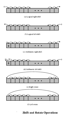
Conversion
Conversion instructions are those that change the format or operate on the format of data. An example is converting from decimal to binary.
Input/output
As we saw, there are a variety of approaches taken, including isolated programmed IO, memory-mapped programmed I/O, DMA, and the use of an I/O processor. Many implementations provide only a few I/O instructions, with the specific actions specified by parameters, codes, or command words.
System Controls
System control instructions are those that can he executed only while the processor is in a certain privileged state or is executing a program in a special privileged area of memory, typically, these instructions are reserved for the use of the operating system.
Some examples of system control operations are as follows. A system control instruction may read or alter a control register. Another example is an instruction to read or modify a storage protection key, such us is used in the S/390 memory system. Another example is access to process control blocks in a multiprogramming system.
Transfer of control
For all of the operation types discussed so far. The next instruction to be performed is the one that immediately follows, in memory, the current instruction. However, a significant fraction of the instructions in any program have as their function changing the sequence of instruction execution. For these instructions, the operation performed by the CPU is to update the program counter to contain the address of some instruction in memory.
There are a number of reasons why transfer-of-control operations are required. Among the most important are the following:
1. In the practical use of computers, it is essential to be able to execute each instruction more than once and perhaps many thousands of times. It may require thousands or perhaps millions of instructions to implement an application. This would be unthinkable if each instruction had to be written out separately. If a table or a list of items is to be processed, a program loop is needed. One sequence of instructions is executed repeatedly to process all the data.
2. Virtually all programs involve some decision making. We would like the computer to do one thing if one condition holds, and another thing if another condition holds. For example, a sequence of instructions computes the square root of a number. At the start of the sequence, the sign of the number is tested, If the number is negative, the computation is not performed, but an error condition is reported.
3. To compose correctly a large or even medium-size computer program is an exceedingly difficult task. It helps if there are mechanisms for breaking the task up into smaller pieces that can be worked on one at a time.
We now turn to a discussion of the most common transfer-of-control operations found in instruction sets: branch, skip, and procedure call.
8. What is Procedure call instructions?
Perhaps the most important innovation in the development of programming languages is the procedure, a procedure is a self-contained computer program that is incorporated into a larger program. At any point in the program the procedure may he invoked, or called. The processor is instructed to go and execute the entire procedure and then return to the point from which the call took place.
The two principal reasons for the use of procedures are economy and modularity. A procedure allows the same piece of code to be used many times. This is important for economy in programming effort and for making the most efficient use of storage space in the system (the program must be stored). Procedures also allow large programming tasks to be subdivided into smaller units. This use of modularity greatly eases the programming task.
The procedure mechanism involves two basic instructions: a call instruction that branches from the present location to the procedure, and a return instruction that returns from the procedure to the place from which it was called. Both of these are forms of branching instructions.
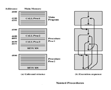
The above figure illustrates the use of procedures to construct a program. In this example, there is a main program starting at location 4000. This program includes a call to procedure PROC1, starting at location 4500. When this call instruction is encountered, the CPU suspends execution of the main program and begins execution of PROC1 by fetching the next instruction from location 4500. Within PROC1, there are two calls to PR0C2 at location 4800. In each case, the execution of PROC1 is suspended and PROC2 is executed. The RETURN statement causes the CPU to go back to the calling program and continue execution at the instruction after the corresponding CALL instruction. This behavior is illustrated in the right of this figure.
Several points are worth noting:
1. A procedure can be called from more than one location.
2. A procedure call can appear in a procedure. This allows the nesting of procedures to an arbitrary depth.
3. Each procedure call is matched by a return in the called program.
Because we would like to be able to call a procedure from a variety of points, the CPU must somehow save the return address so that the return can take place appropriately. There are three common places for storing the return address:
• Register
• Start of called procedure
• Top of stack
9. Explain in detail Addressing Modes
The address field or fields in a typical instruction format are relatively small. We would like to be able to reference a large range of locations in main memory or for some systems, virtual memory. To achieve this objective, a variety of addressing techniques has been employed. They all involve some trade-off between address range and/or addressing flexibility, on the one hand, and the number of memory references and/or the complexity of address calculation, on the other. In this section, we examine the most common addressing techniques:
- Immediate
- Direct
- Indirect
- Register
- Register indirect
- Displacement
Immediate Addressing
The simplest form of addressing is immediate addressing, in which the operand is actually present in the instruction:
- Operand is part of instruction
- Operand = address field
- e.g. ADD 5 ;Add 5 to contents of accumulator ;5 is operand

The advantage of immediate addressing is that no memory reference other than the instruction fetch is required to obtain the operand, thus saving one memory or cache cycle in the instruction cycle.
The disadvantage is that the size of the number is restricted to the size of the address field, which, in most instruction sets, is small compared with the word length.
Direct Addressing
A very simple form of addressing is direct addressing, in which:
- Address field contains address of operand
- Effective address (EA) = address field (A)
- e.g. ADD A ;Add contents of cell A to accumulator
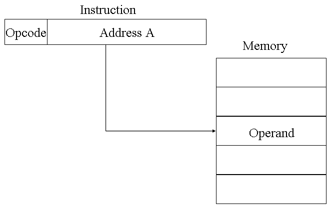
The technique was common in earlier generations of computers but is not common on contemporary architectures. It requires only one memory reference and no special calculation. The obvious limitation is that it provides only a limited address space.
Indirect Addressing
With direct addressing, the length of the address field is usually less than the word length, thus limiting the address range. One solution is to have the address field refer to the address of a word in memory, which in turn contains a full-length address of the operand. This is known as indirect addressing.
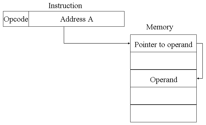
Register Addressing
Register addressing is similar to direct addressing. The only difference is that the address field refers to a register rather than a main memory address.
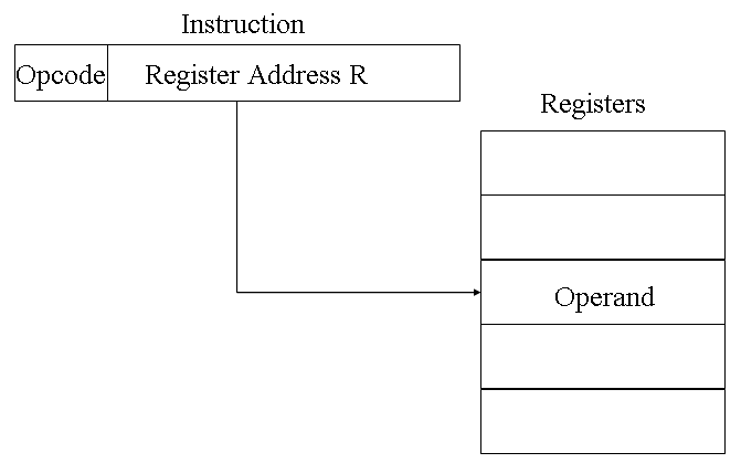
The advantages of register addressing are that :
- Only a small address field is needed in the instruction
- No memory 'references are required, faster instruction fetch
The disadvantage of register addressing is that the address space is very limited.
Register Indirect Addressing
Just as register addressing is analogous to direct addressing, register indirect addressing is analogous to indirect addressing. In both cases, the only difference is whether the address field refers to a memory location or a register. Thus, for register indirect address: Operand is in memory cell pointed to by contents of register.
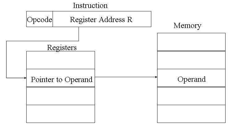
The advantages and limitations of register indirect addressing are basically the same as for indirect addressing. In both cases, the address space limitation (limited range of addresses) of the address field is overcome by having that field refer to a word-length location containing an address. In addition, register indirect addressing uses one less memory reference than indirect addressing.
Displacement Addressing
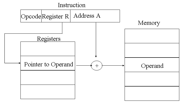
A very powerful mode of addressing combines the capabilities of direct addressing and register indirect addressing. It is known by a variety of names depending on the context of its use but the basic mechanism is the same. We will refer to this as displacement addressing, address field hold two values:
- A = base value
- R = register that holds displacement
10. Explain Instruction Format & 0-1-2-3 address formats
Computer perform task on the basis of instruction provided. An instruction in computer comprises of groups called fields. These field contains different information as for computers every thing is in 0 and 1 so each field has different significance on the basis of which a CPU decide what to perform. The most common fields are:
- Operation field which specifies the operation to be performed like addition.
- Address field which contain the location of operand, i.e., register or memory location.
- Mode field which specifies how operand is to be founded.
An instruction is of various length depending upon the number of addresses it contain. Generally CPU organization are of three types on the basis of number of address fields:
- Single Accumulator organization
- General register organization
- Stack organization
In first organization operation is done involving a special register called accumulator. In second on multiple registers are used for the computation purpose. In third organization the work on stack basis operation due to which it does not contain any address field. It is not necessary that only a single organization is applied a blend of various organization is mostly what we see generally.
On the basis of number of address, instruction are classified as:
Note that we will use X = (A+B)*(C+D) expression to showcase the procedure.
- Zero Address Instructions –
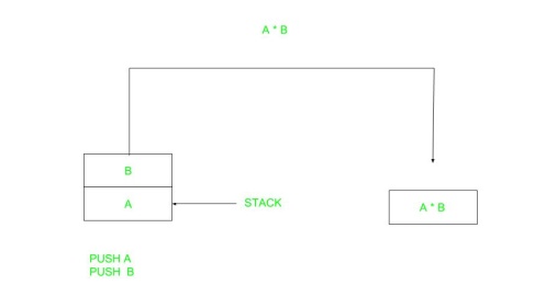
A stack based computer do not use address field in instruction. To evaluate a expression first it is converted to revere Polish Notation i.e. Post fix Notation.
Expression: X = (A+B)*(C+D)
Postfixed : X = AB+CD+*
TOP means top of stack
M[X] is any memory location
PUSH | A | TOP = A |
PUSH | B | TOP = B |
ADD |
| TOP = A+B |
PUSH | C | TOP = C |
PUSH | D | TOP = D |
ADD |
| TOP = C+D |
MUL |
| TOP = (C+D)*(A+B) |
POP | X | M[X] = TOP |
2. One Address Instructions –
This use a implied ACCUMULATOR register for data manipulation. One operand is in accumulator and other is in register or memory location. Implied means that the CPU already know that one operand is in accumulator so there is no need to specify it.

Expression: X = (A+B)*(C+D)
AC is accumulator
M[] is any memory location
M[T] is temporary location
LOAD | A | AC = M[A] |
ADD | B | AC = AC + M[B] |
STORE | T | M[T] = AC |
LOAD | C | AC = M[C] |
ADD | D | AC = AC + M[D] |
MUL | T | AC = AC * M[T] |
STORE | X | M[X] = AC |
3. Two Address Instructions –
This is common in commercial computers. Here two address can be specified in the instruction. Unlike earlier in one address instruction the result was stored in accumulator here result cab be stored at different location rather than just accumulator, but require more number of bit to represent address.

Here destination address can also contain operand.
Expression: X = (A+B)*(C+D)
R1, R2 are registers
M[] is any memory location
MOV | R1, A | R1 = M[A] |
ADD | R1, B | R1 = R1 + M[B] |
MOV | R2, C | R2 = C |
ADD | R2, D | R2 = R2 + D |
MUL | R1, R2 | R1 = R1 * R2 |
MOV | X, R1 | M[X] = R1 |
4. Three Address Instructions –
This has three address field to specify a register or a memory location. Program created are much short in size but number of bits per instruction increase. These instructions make creation of program much easier but it does not mean that program will run much faster because now instruction only contain more information but each micro operation (changing content of register, loading address in address bus etc.) will be performed in one cycle only.

Expression: X = (A+B)*(C+D)
R1, R2 are registers
M[] is any memory location
ADD | R1, A, B | R1 = M[A] + M[B] |
ADD | R2, C, D | R2 = M[C] + M[D] |
MUL | X, R1, R2 | M[X] = R1 * R2 |