UNIT 2
Ans.
of a pointer over a calibrated scale.
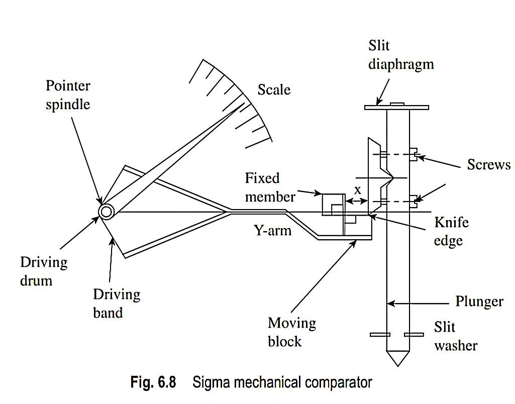
In addition, the second level of magnification can be adjusted by using driving drums of different radii (r).
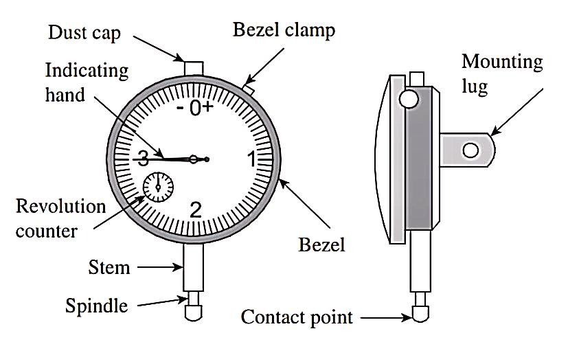
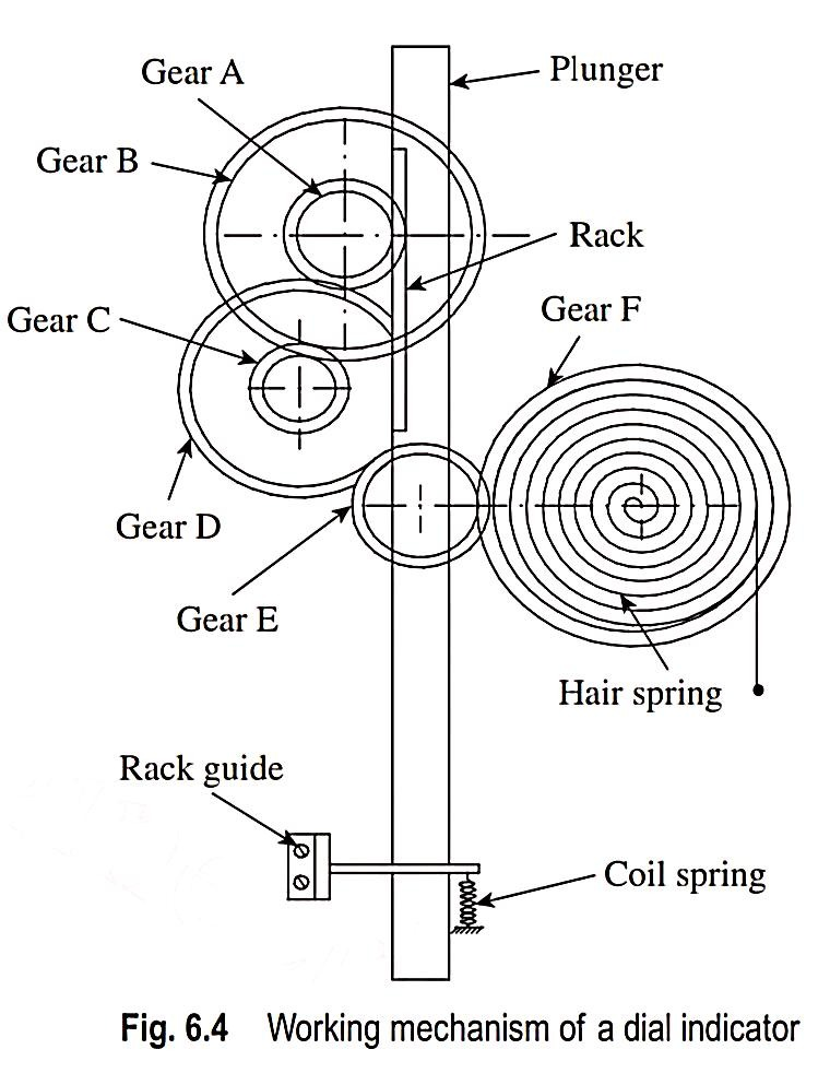
2. With sketch, describe the construction and working of dial indicator.
Ans.
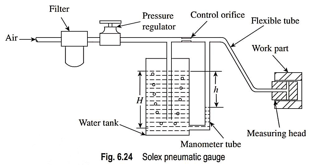
3. With sketch, describe the construction and working of pneumatic comparator.
Ans.
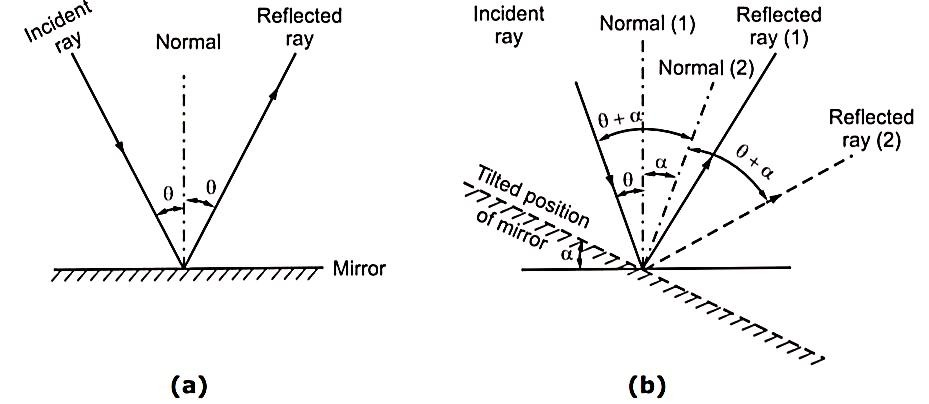
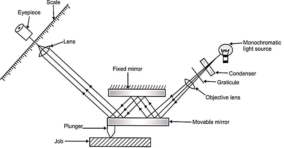
4. With sketch, describe the construction and working of optical comparator.
Ans.




5. With sketch, describe the construction and working LVDT.
Ans.
element.
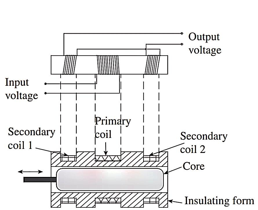
changes 180° through the null.
between outputs resulting from displacements on either side of the null.
For such displacements, which are within the linear range of the instrument, output voltage is a linear function of core displacement.
6. Explain different thread form errors.
Ans.
(a) Major and minor diameter errors:
between mating threads or a reduction in the flank contact.
(b) Effective diameter error:
(c) Pitch errors:
(a) Non-uniform tool work velocity ratio.
(b) Lack of lead screw squareness, while cutting the thread.
(c) Eccentric mounting of the gears between the lead screw and spindle.
(d) Error in the teeth of gears between the lead screw and spindle.
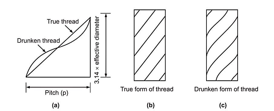
ii. Drunkenness or Drunken Thread Error

iii. Progressive Pitch Error
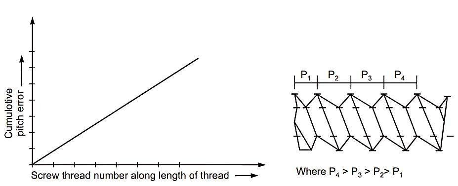
(a) Incorrect ratio of the linear velocity of tool and angular
velocity of the work.
(b) Pitch error in the lead screw of lathe or other machine
used for thread cutting.
(c) Use of incorrect gear or gear train between work and
lead screw..
iv. Irregular or Erratic Errors
(a) Machine faults.
(b) Disturbances in the machining set up,
(c) Variations in the cutting properties of the material etc.
(d) Irregular cutting action resulting from non-uniformity in the material of the screw.
7. Explain procedure of measurement of minor diameter.
Ans.
8. Explain procedure of measurement of major diameter.
Ans.
9. Explain procedure of measurement of effective diameter.
Ans.
Three-wire Method
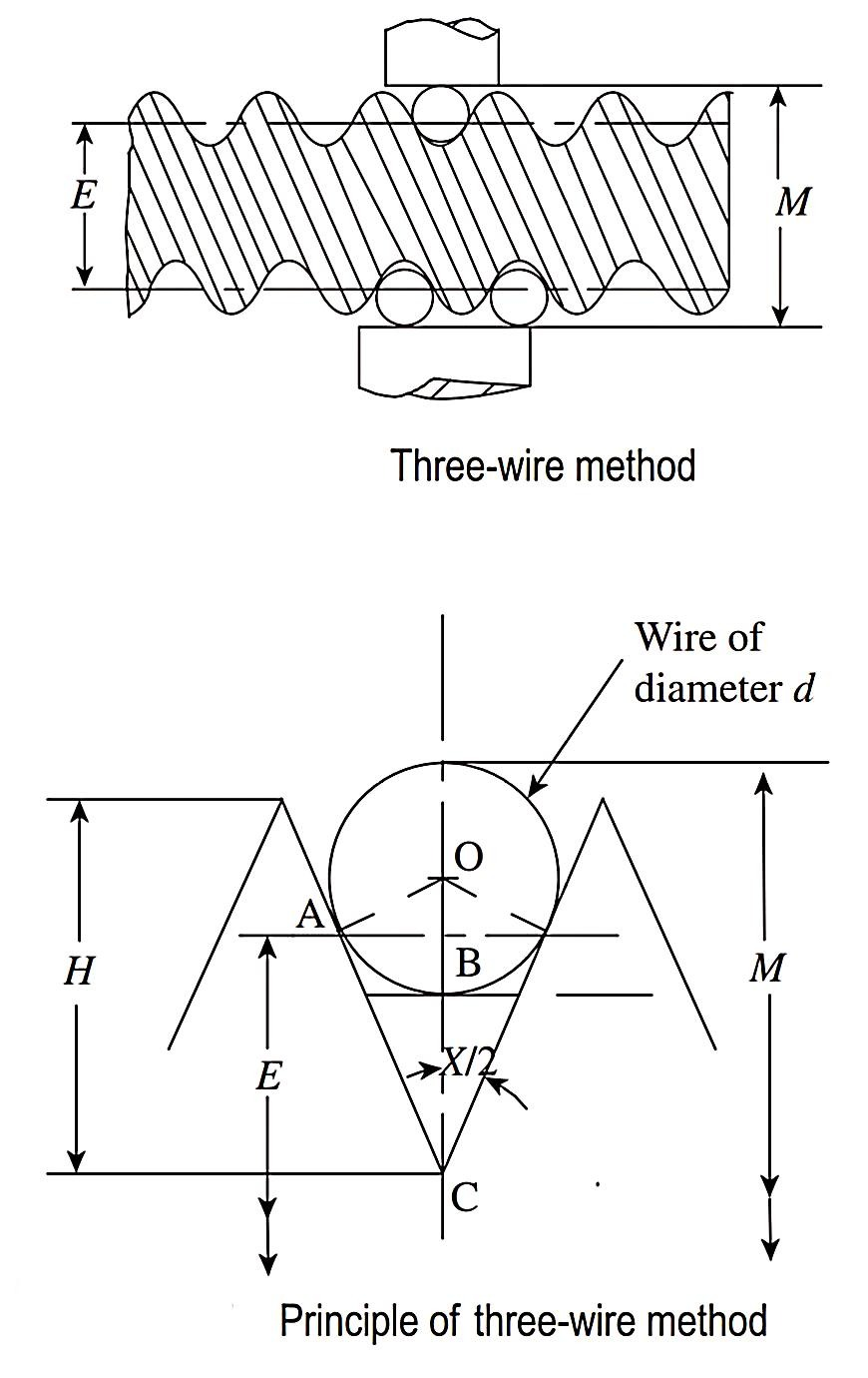
Now, OC = OA cosec (x/2) = d/2 cosec (x/2)
H = p/2 cot (x/2) and, therefore, BC = H/2 = p/4 cot (x/2)
If h is the height of the center of wire from the pitch line,
then h = OC − BC.
h = d/2cosec (x/2) – p/4 cot (x/2)
Distance over wires, M = E + 2h + 2r,
where r is the radius of the wires.
Therefore, effective diameter
E = M − d cosec (x/2) + p/2 cot (x/2) − d
E = M − d[1 + cosec (x/2)] + p/2cot (x/2)
10. Explain procedure of measurement of pitch.
Ans.
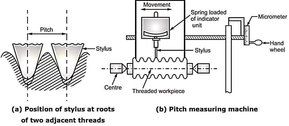
11. Explain working of floating carriage micrometer.
Ans.
Floating Carriage Dial Micrometer is also commonly known as “effective diameter
measuring micrometer” or “floating carriage diameter measuring machine”,
working on micrometer principle (screw and nut).
• In fact, floating carriage diameter measuring is the bench micrometer mounted
on a carriage machine.
Working Principle:
When drum of micrometer rotates by one revolution, it will move forward by a
distance equal to pitch of an internal thread. This movement is measured by using
number of divisions engraved on drum and main scale.
• This instrument is used for accurate measurement of 'Thread Plug Gauges'. Most
important gauge dimensions such as Major diameter, Effective diameter, and
Minor diameter are measured with the help of this instrument.
• All these dimensions have a vital role in the thread plug gauges, since the
accuracy and interchangeability of the component depends on the gauges used.
To reduce the effect of slight errors in the micrometer screws and measuring
faces, this micrometer is basically used as comparator.
Construction:
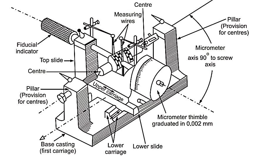
• Features of Floating carriage diameter measuring machines are,
(a) Robust or sturdy cast iron base.
(b) Suitable for dimensional stability.
(c) Internal ways ground (finished by grinding) to finest accuracy.
(d) Micrometer least count of the order 0.002 mm with non-rotary spindle.
Metrology and Quality Control 5.7 Screw Thread Measurements
• The machine consists of three units,
(a) A base casting carries a pair of accurately mounted and aligned centers, on
which the threaded workpiece is mounted i.e. first carriage.
(b) Second carriage known as lower carriage is mounted on the first carriage at
exactly 90°. It is capable to move parallel to thread axis.
(c) Third carriage known as upper carriage is mounted on the second carriage/
lower carriage. This upper carriage is capable to move at 90° to the thread
axis due to provision of V-ball slides.
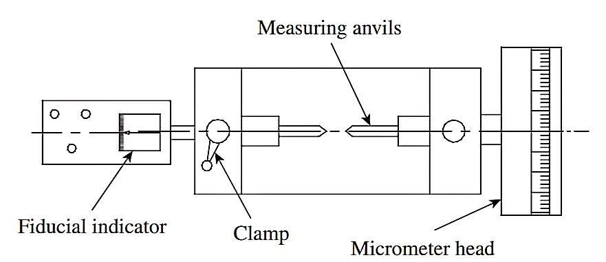
• Upper carriage has micrometer thimble with graduated cylindrical scale at one
end. Micrometer thimble can read upto 0.002 mm. On another end, a fiducial
indicator is used in placed of fixed anvil, to perform all measurements at same
pressure. Both, micrometer thimble and fiducial indicator have special
exchangeable anvils made to suit the form of thread.
12. What are the various types of errors in spur gear?
Ans.
From a metrological point of view, the major types of errors are as follows:
2. Gear tooth profile errors
3. Gear tooth errors
4. Pitch errors
5. Runout errors
6. Lead errors
7. Assembly errors
13. Explain the uses of gear tooth Vernier.
Ans.
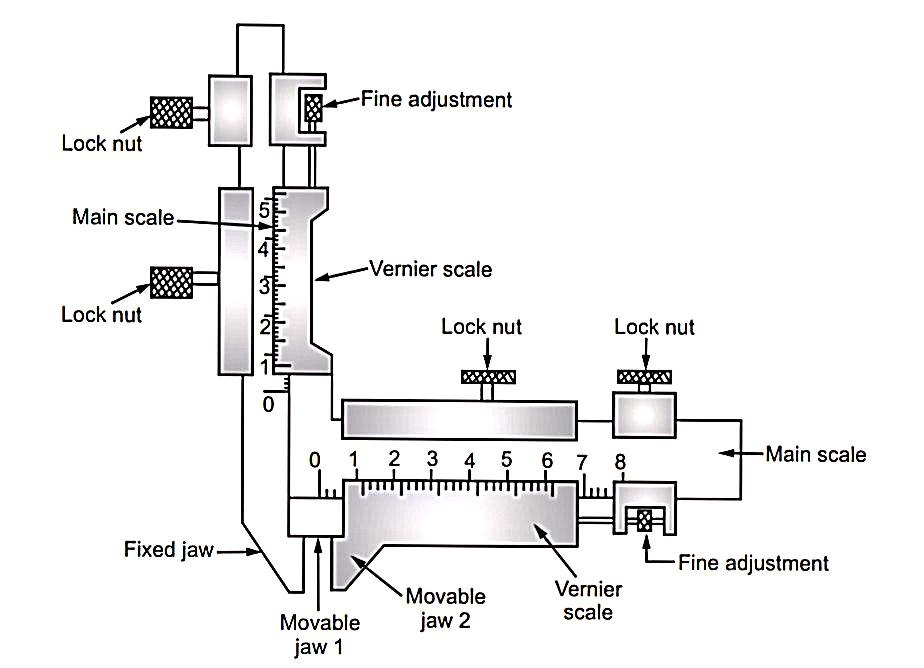
w = N H m sin 
d = 
14. Explain constant cord.
Ans.
Working Principle:

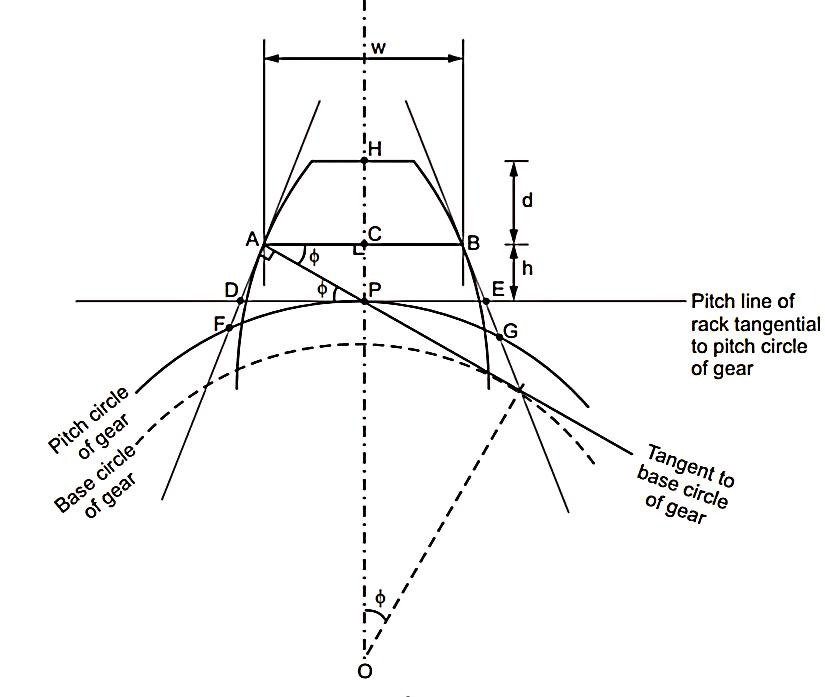
(a) Pitch line of rack is tangent to pitch circle of gear
(b) [Tooth thickness of rack measured along its pitch line] = [ Arc tooth thickness
of gear tooth measured
along its pitch circle] Distance 'DE' = Arc distance 'FG'
Constant chord (AB) 'w' = 
Depth ‘d’ = m 
Where m = module &  pressure angle
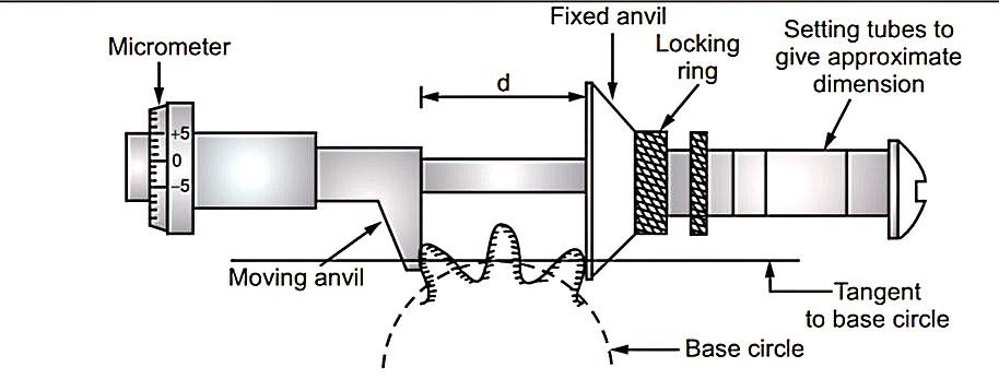
15. Explain base tangent.
Ans.
(i) the measurement depends upon two vernier readings, each of which, is a function of other and
(ii) the measurement is made the faces of its measuring jaws, which itself are the causes of inaccurate measurements.
(iii) comparatively more sensitive than chordal thickness method.
(iv) This method does not depend on number of teeth.
d = 
where, N = Number of teeth
m = Module
S = Number of teeth between two anvils
 = Pressure angle
16. With sketch, describe the construction and working gear rolling tester.
Ans.
(i) Acceptable, (ii) Rejectionable, before leading to assembly section.
Advantages of Rolling Gear Test
17. With sketch, describe the construction and working profile projector.
Ans.
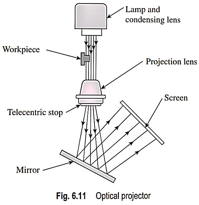
1. Inspection of elements of gears and screws
2. Measurement of pitch circle diameters of holes located on components
3. Measurement of unusual profiles on components such as involute and cycloidal, which are difficult to measure by other means
4. Measurement of tool.
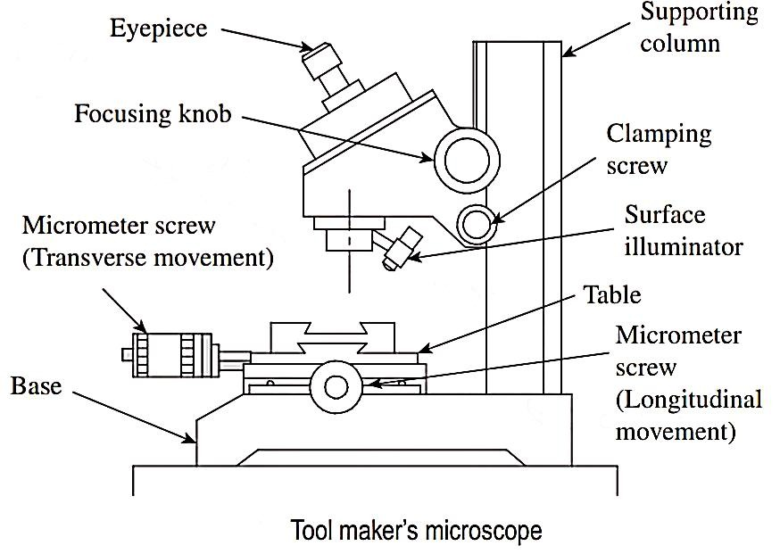
18. With sketch, describe the construction and working Tool makers microscope & state its application.
Ans.
19. With sketch, Explain primary & secondary texture.
Ans.
1. Primary texture
(i) Irregularities of third order (irregularities due to feed marks of cutting tool) and
(ii) Irregularities of fourth order (irregularities due to rupture of material caused due to separation of chip).
(i) Cutting tool shape,
(ii) Tool feed rate,
(iii) Friction,
(iv) Wear,
(v) Corrosion etc.
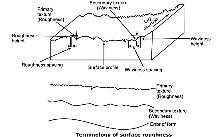
(i) irregularities of first order, (irregularities due to lack of straightness of guide-ways of tool, deformation of work under cutting forces, weight of material itself) and
(ii) Second order (irregularities due to vibrations and chatter marks).
20. Explain various parameters for measuring surface roughness.
Ans.
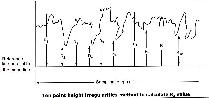
1. Ten Point Height Method (Rz):
2. R.M.S. Value:

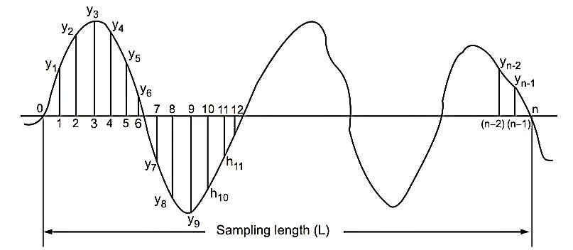
3. Centre Line Average Method or CLA Value:
CLA = 
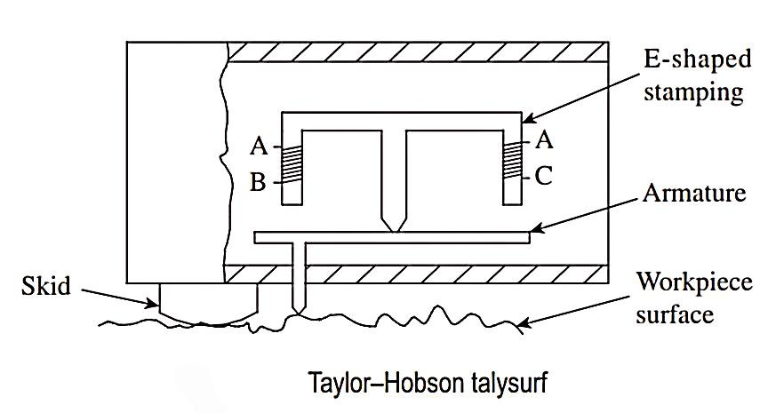
21. With sketch, explain Surface roughness measuring instrument: Talysurf
Ans.
