Unit 1
Spur Gear
Q1) Classify gears.
Ans.
- Parallel
b. Intersecting
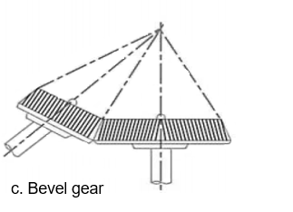
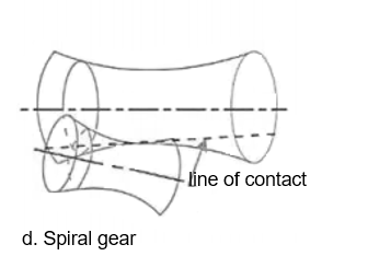
c. Non-intersecting and non-parallel

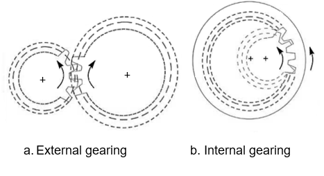
2. According to the type of gearing.
d. External gearing
e. Internal gearing
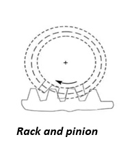
f. Rack and pinion
3. According to the position of teeth on the gear surface
g. Straight
h. Inclined
i. Curved.
Q2) Define spur gear.
Ans.
Q3) Define pitch circle, pressure angle, addendum, dedendum.
Ans.

2. Define diametral pitch, module, circular pitch, face width.
Ans.
It is denoted by 
Mathematically,
Diametral pitch 
T=number of teeth
D=pitch circle diameter
Module m=D/T

Mathematically,
Circular pitch. 
D=diameter of the pitch Circle, and
T= number of teeth on the wheel
Q4) Differentiate between involute & cycloidal teeth.
Ans
Sr No. | Cycloidal teeth | Involute teeth |
1 | Pressure angle varies from a maximum at the beginning of the engagement, reduces to zero at the pitch, and again increases to a maximum at the end of engagement resulting in the less smooth running of the gears. | The pressure angle is constant throughout the engagement of teeth. This results in the smooth running of the gears. |
2 | It involves a double curve for the teeth, epicycloid, and hypocycloid. This complicates the manufacture. | It involves a single curve for the teeth resulting simplicity of manufacturing and tools. |
3 | Owing to the difficulty of manufacture these are costlier | These are simple to manufacture and thus cheaper. |
4 | Exact center distance is required to transmit a constant velocity ratio | A little variation in the center distance does not affect the velocity ratio |
5 | The phenomenon of interference does not occur at all | Interference can occur if the condition of a minimum number of teeth on a gear is not followed |
6 | The teeth have spreading flanks and thus are stronger | The teeth have radial flanks and thus are weaker as compared to the cycloidal form for the same pitch. |
7 | In this, convex flank always has contact with a concave face resulting in less wear | Two convex surfaces are in contact and do there is more wear. |
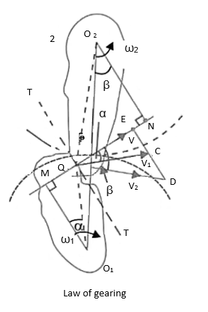
Q5) Explain the law of gearing.
Ans.


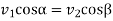

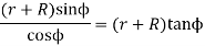
 ………. I
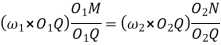
Also, from similar triangles 
 ……….. II
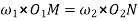
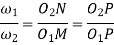
Combining equations, I and II we have

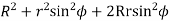
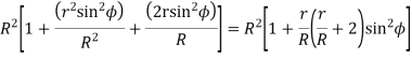
Q6) Derive an expression for the path of contact & arc of contact.
Ans.
Let.  radius of the addendum circle of the pinion.
 radius of the addendum circle of the wheel.
 = radius of pitch Circle of pinion, and
 radius of pitch Circle of the wheel.
From the figure, we find that radius of the base circle of pinion
And the radius of the base circle of the wheel,
Now from right angle triangle 

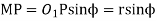
Length of the part of the path of contact, or the path of approach,

Similarly from right-angled triangle 
And 
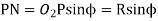
Length of the part of the path of contact, or the path of recess

Length of the path of contact,

Arc of contact

We know that the angle of the arc of approach

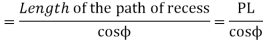
And the length of the arc of recess
Since the length of the arc of contact GPH is equal to the sum of the length of the arc of approach and arc of recess, therefore,
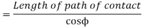
Length of the arc of contact

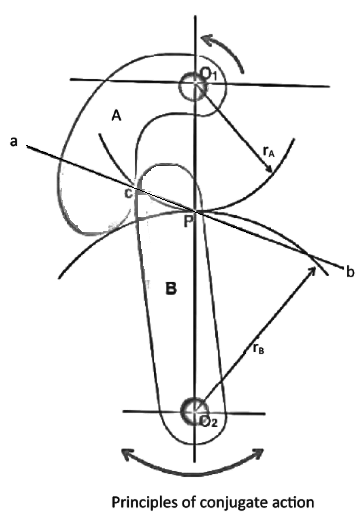
Q7) Explain conjugate action in gears.
Ans

Where  =Angular velocity of the driver.
 =Angular velocity of the driven


Q8) Explain interference in gears with neat sketch.
Ans.


The maximum length of the path of approach,

And the maximum length of the path of recess,

The maximum length of the path of contact

The maximum length of the Arc of contact
Q9) Explain different methods to avoid interference.
Ans.
In general, there are three different ways of reducing or eliminating interference and subsequent undercutting at the flank region, when a pinion has less than a minimum number of teeth to avoid interference.

2. By modifying addendum of gear tooth
3. Increased center distance


Q10) Explain undercutting with a neat sketch.
Ans.
Undercutting

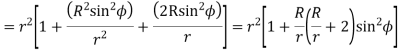
Q11) Derive an expression for the minimum number of teeth on the pinion to avoid interference.
Ans.
Let. t= the number of teeth on the pinion.
T= number of teeth on the wheel
m = module of the teeth
r= pitch Circle radius of pinion =m.t/2
G= Gear ratio =T/t =R/r
 = Pressure angle or angle of obliquity

From triangle 


Where 
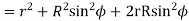
Limiting the radius of the pinion addendum circle,

Let  = addendum of the pinion, where
  is a fraction by which the standard addendum of one module for the pinion should be multiplied to avoid interference.
We know that the addendum of the pinion.


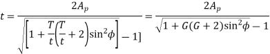
This equation gives the minimum number of teeth required on the pinion to avoid interference.
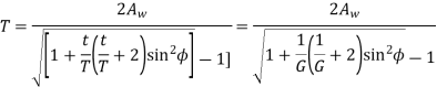
Q12) Derive an expression for a minimum number of teeth on gear to avoid interference.
Ans.
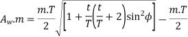
Let. T= minimum number of teeth required on the wheel to interference,
 .m= addendum of the wheel, where
  is a fraction by which the standard addendum for the wheel should be multiplied.
Using the same notations as in the above article we have from triangle 

=
Where 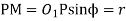
=
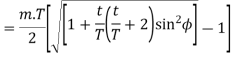
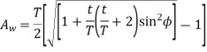
Limiting the radius of wheel addendum circle
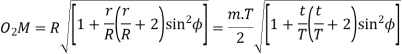
We know that addendum of the wheel

Q13) Explain gear friction & its remedies.
Ans.
(1) gear scuffing failures due to excessive heat generation and gear contact fatigue lives and associated failure modes of spalling and micro-pitting
(2) load-dependent (mechanical) gear mesh power losses, and
(3) a class of gear vibrations along the direction of the relative sliding and the damping effects along the line of action.
The following methods are used to reduce gear friction.
2. Lower speeds and loads.
3. Lubrication.
4. Material selection.


