Unit II
Helical, Bevel, Worm and Worm Wheel
Q1) Define helix angle, axial pitch & normal pitch.
Ans.
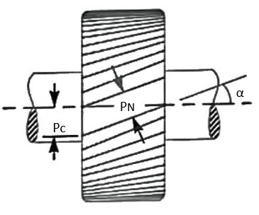


The normal pitch may also be defined as the circular pitch in the normal plane which is a plane perpendicular to the teeth. Mathematically, normal pitch, 
Q2) Write down geometrical relationships for helical gears.
Ans.
Pressure angle in the plane of rotation, ϕ =15° to 25°
Helix angle α = 20° to 45°
Addendum=0.8m
Dedendum= 1m
Minimum total depth= 1.8m
Minimum clearance=0.2m
Thickness of tooth=1.5708m
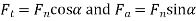
Q3) Explain tooth forces in helical gears.
Ans.
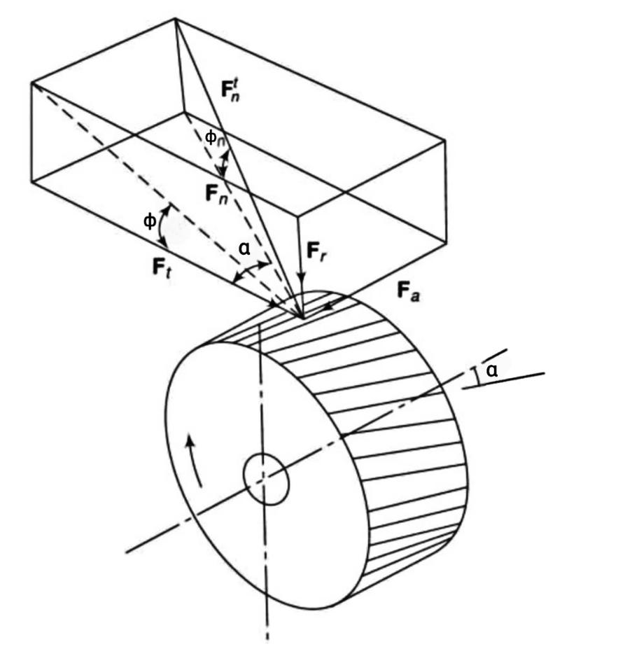
Let  =total normal force
 =tangential force
 =axial force
 =radial force
 =normal force in the plane of
 =Pressure angle
 =Normal pressure angle
 =Helix angle
Then

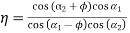
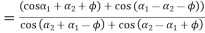
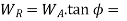
Q4) Derive an expression for the efficiency of the spiral gear.
Ans.
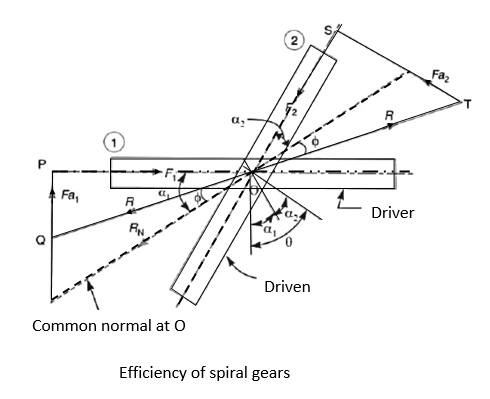
 force applied tangentially on the driver,
 =resisting force acting tangentially on the driven.
 axial or end thrust on the driver
 =axial or end thrust on the driven
 = normal reaction at the point of contact,
 = Angle of friction
R= resultant reaction at the point of contact
From triangle OPQ, 
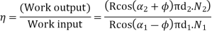
Work input to the driver

From triangle OST,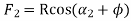
The work output of the driven

The efficiency of spiral gears,
 ………… 1
t pitch circle diameter of gear 1,

And pitch circle diameter of Gear 2
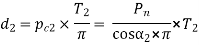
 ……………. 2
We know that  ……………. 3
Multiplying equation 2 and 3 we get

Substituting this value in equation 1 we get
 …….. 4
 ………… 5
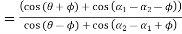
Since the angles are constants, therefore the efficiency will be maximum, when.
 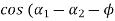 ) Is maximum.
 or
or 
Since  , therefore
Similarly, 
Similarly,  in the equation we get
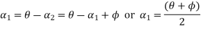
Q5) Derive an expression for virtual teeth for helical gears.
Ans.
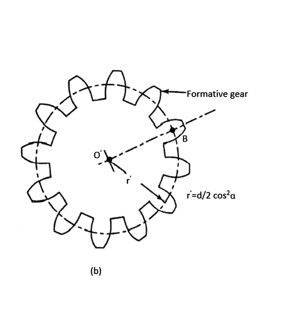


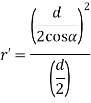
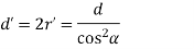
Where a and b are semi-major and semi-minor axis respectively.


Where, T= actual number of teeth on a helical gear, and
 =Helix angle
Q6) Define pitch cone, addendum angle, dedendum angle, face angle, root angle, back cone & backing.
Ans.

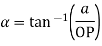
a= Addendum and OP=Cone distance
3. Dedendum angle:- It is the angle subtended by the dedendum of the tooth at the cone center. It is denoted by  mathematically, dedendum angle,
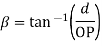
d= Dedendum and OP=Cone distance
4. Face angle:- It is the angle subtended by the face of the tooth at the cone center. It is denoted by  . The face angle is equal to the pitch angle plus addendum angle.
5. Root angle:- It is the angle subtended by the root of the tooth at the cone center. It is denoted by  . It is equal to the pitch angle minus the dedendum angle.
6. Back cone:- It is an imaginary cone, perpendicular to the pitch cone at the end of the tooth.
7. Backing:- It is the distance of the pitch. From the back of the boss, parallel to the pitch point of the gear. It is denoted by B.
Q7) Write down geometrical relationships for bevel gears.
Ans.
The proportions for the bevel gears may be taken as follows:-
Where m is the module.
Q8) Explain tooth forces in bevel gears.
Ans.
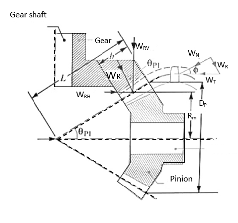


And the radial force acting on the pinion shaft,

Q9) Define axial pitch, lead, lead angle, normal pitch & helix angle.
Ans.
2. Lead:- It is the linear distance through which a point on a thread moves ahead in one revolution of the worm. For single start thread lead is equal to the axial pitch, but for multiple start threads, lead is equal to the product of pitch and number of stars. Mathematically,

 = axial pitch; n=number of starts.
3. Lead angle:- It is the angle between the tangent to the thread helix on the pitch cylinder and the plane normal to the axis of the worm. It is denoted by  .
.
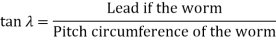

m =module, and
 =pitch circle diameter of the worm.
4. Normal pitch:- It is the distance measured along the normal to the threads between two corresponding points on two adjacent threads of the worm. Mathematically,
Normal pitch, 
5. Helix angle:- It is the angle between the tangent to the thread helix on the pitch cylinder and the axis of the worm. It is denoted by .
.
Q10) Write down geometrical relationships for worm & worm wheel.
Ans.
Proportions for the worm
SR.No. | Particulars | Single and double threaded worms | Triple and quadruple threaded worms |
1 | Normal-pressure angle | 14.5° | 20° |
2 | Pitch circle diameter for worms integral with the shaft |
|
|
3 | Pitch circle diameter for worms’ board to fit over the shaft | 2.4 |
|
4 | Maximum bore for shaft |
|
|
5 | Hub diameter |
|
|
6 | Face length |
|
|
7 | Depth of tooth |
|
|
8 | Addendum |
|
|


Proportions for worm gear
Sr No. | Particulars | Single and double threads | Triple and quadruple threads |
1 | Normal-pressure angle |
| 20 |
2 | Outside diameter |
|
|
3 | Throat diameter |
|
|
4 | Face width |
|
|
5 | The radius of gear face |
|
|
6 | The radius of gear rim |
|
|


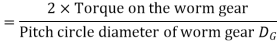
Q11) Explain tooth forces in worm & worm wheel.
A11)
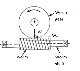
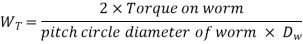
= Axial force or thrust on the worm gear.
The tangential force on the worm produces a twisting moment of magnitude  x
x  and bands the worm in the horizontal plane.
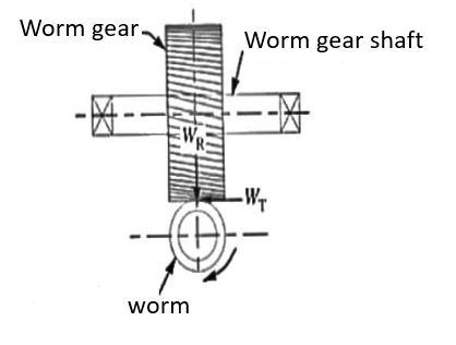
2. The axial force of thrust on the worm
 =tangential force on the worm gear.
The axial force on the worm tends to move the worm axially, includes an axial load on the bearings and bends the worm in a vertical plane with a bending moment of magnitude  x
x  .
.
3. Radial or separating force on the worm
 Radial or separating force on the worm gear.
The radial or separating force tends to force the worm and worm gear out of the match. This force also bends the worm in the vertical plane.


