UNIT 6
Step–Less-Regulation (Theoretical Treatment only) & Gyroscope
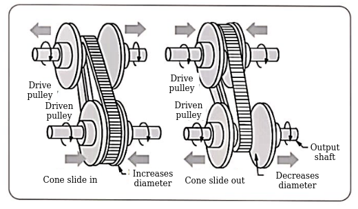
Q1) Explain continuous variable transmissions.
Ans.
Continuous variable transmission
Principle of Pulley based CVT system
Advantages of CVT system:
Limitations of CVT system:
Applications of CVT system:
Q2) Explain face plate variators.
Ans.
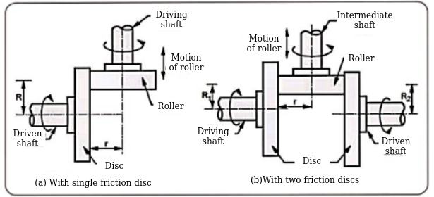


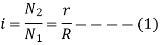
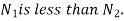
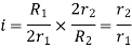
Where, i=instantaneous transmission ratio
 Speed of driving shaft
 Speed of driven shaft
r= contact radius of roller
R=contact radius of disc
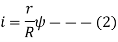
Where  =Slip factor=0.97 to 0.98
Specifications

Where. r=contact radius of roller
 contact radii of discs
Advantages of faceplate variators
Limitation of faceplate variators
Application of faceplate variators
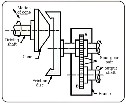
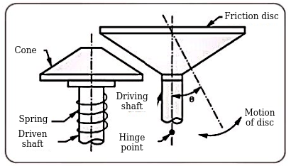
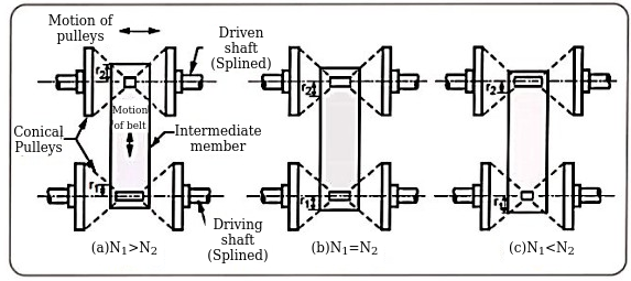
Q3) Explain conical variators.
Ans.
Cone variator with non-parallel shafts
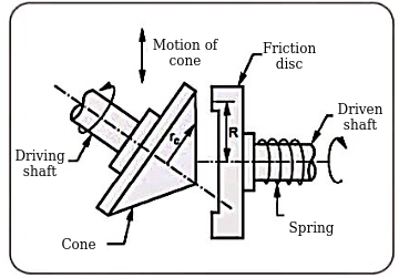

Where  radius of friction cone at the point of contact
R= radius of friction disc
Specifications

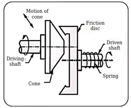
Cone variator with parallel shafts
Specifications

Cone variator with planetary mechanism
Specifications

Cone variator with swivelling disc
Specifications

Advantages of conical variator
Limitations of conical variator
Applications of conical variator
Q4) Explain spheroidal & cone variators.
Ans.
Spheroidal variator with swivelling discs
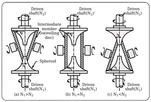
Specifications

Cone variators with spheres supported on shafts
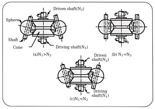


Specifications

Advantages of spheroidal and cone variators
Limitations of spheroidal and cone variators
Spheroid must be hardened to improve wear resistance.
Q5) Explain Variators with axially displaceable cones.
Ans.


V belt:-
Specifications

Nylon belt
Steel ring
Specifications

Chain
Specifications

Q6) Explain PIV drives.
Ans.
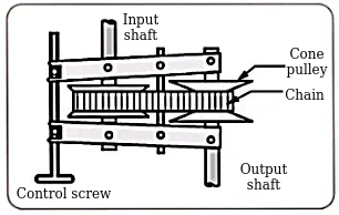
Applications:
Also used in feed drives of lathe machines and drilling machines
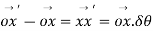
Q7) Explain gyroscopic forces and Couples.
Ans.
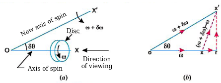


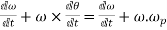
Component of angular acceleration in the direction of ox.
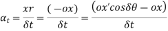
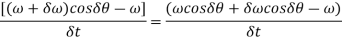
Since  is very small, therefore substituting
  we have
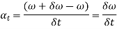
In the limit, when 
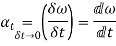
Component of angular acceleration in the direction perpendicular to ox,
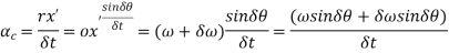
Since  is very small, therefore substituting,
  , we have
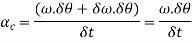
In the limit when 
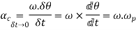
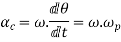
Total angular acceleration of the disc
= 


Gyroscopic couple


Let. I=mass moment of inertia of the disc about OX, and
 = Angular velocity of the disc.
Angular momentum of the disc 


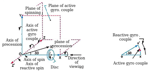
Change in angular momentum

And rate of change of angular momentum
=
Since the rate of change of angular momentum will result by the application of a couple to the disc, therefore the couple applied to the disc causing precession.
Where  = angular velocity of precision of the axis of spin or the speed of rotation of the axis of the spin about the axis of precision OY.
In SI units, the units of C in N-m when I is in 
It may be noted that


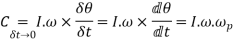
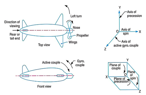
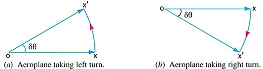
Q8) Explain Gyroscopic stabilisation for Aeroplane
Ans.
Let.  = Angular velocity of the engine in rad/s
m= mass of the engine and the propeller in kg.
k= its radius of gyration in metres.
I=mass momentum of inertia of the engine and the propeller in kg-m^2
= 
v= linear velocity of the aeroplane in m/s
R= radius of curvature in metres, and
 = Angular velocity of precision=v/R rad/s
Gyroscopic couple acting on the aeroplane,

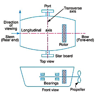
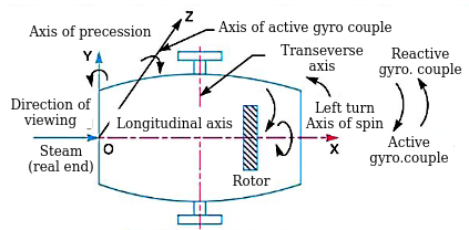
Q9) Explain gyroscopic stabilisation for ship.
Ans.
Terms used in a naval ship
Effect of gyroscopic couple on a naval ship during steering
Effect of gyroscopic couple on a naval ship during pitching

 = Amplitude of Swing maximum angle turned from the mean position in radians, and
 = Angular velocity of S.H.M.
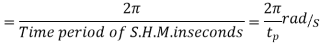
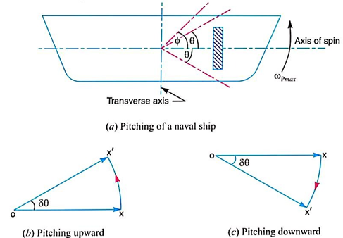
Angular velocity of precision
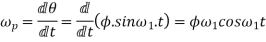
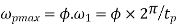
The angular velocity of precession will be maximum if  =1
=1
Maximum angular velocity of precession,
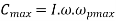
Let I=Moment of inertia of the rotor in  and
and
 = Angular velocity of the rotor in rad/sec
Maximum gyroscopic couple,
Effect of gyroscopic couple on a naval ship during rolling
Hence, there is no effect of the gyroscopic couple acting
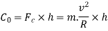
Q10) Explain Stability of four wheel vehicle moving on curved path.
Ans.
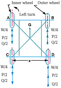
Let m=mass of the vehicle in kg.
W= weight of the vehicle in Newton = m.g
 = radius of the wheels in metres.
R= radius of curvature in metres
h= distance of centre of gravity, vertically above the road surface in metres,
x= width of track in metres,
 = mass moment of inertia of one of the wheels in kg-m^3
 = Angular velocity of the wheels for velocity of spin in rad/s.
 = mass moment of inertia of the rotating parts of the engine
 = Angular velocity of the rotating parts of the the engine in rad/s.
G= gear ratio=
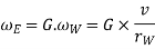
v= linear velocity of the vehicle in m/s =
Therefore
Road reaction over each wheel =W/4=m.g/4 Newton’s
Let us, now consider the effect of the gyroscopic couple and centrifugal couple on the vehicle.
Since the vehicle takes a turn towards left due to the precession and other rotating parts, therefore a gyroscopic couple will act.
We know that velocity of precision,

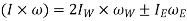
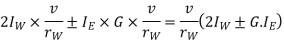
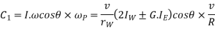
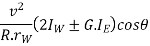
Gyroscopic couple due to four wheels
And gyroscopic couple due to rotating parts of the engine,
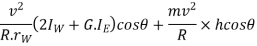
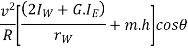
Net gyroscopic couple,

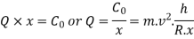
P × x = C. Or. P=C/x
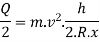
Vertical reaction at each of the outer or inner wheels,
P/2 =C/2x
This gyroscopic couple is balanced by vertical reactions, which are vertically upwards on the outer wheels & vertically downwards on the inner wheels.
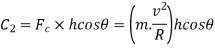
2. Effect of the centrifugal couple

The couple tending to overturn the vehicle or overturning couple,
This overturning couple is balanced by vertical reactions, which are vertically upwards on the outer wheels & vertically downwards on the inner wheels.
Vertical reaction at each of the outer or inner wheels,
Vertical reaction at each of the outer or inner wheels,
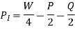
Total vertical reaction at each of the outer wheel,
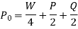
And total vertical reaction at each of the inner wheel,
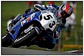
Q11) Explain Stability of a two wheeler vehicle taking a turn.
Ans.
Consider a two wheeler taking a right turn as shown in figure
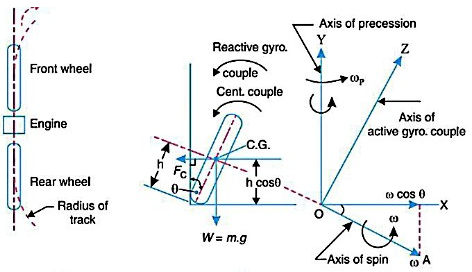
Let m=mass of the vehicle and its rider in kg.
W=weight of the vehicle and its rider in Newton’s =m.g
h= height of the centre of gravity of the vehicle and rider.
 =radius of the wheels,
R= radius of track or curvature.
 =mass moment of inertia of each wheel,
 =mass moment of inertia of the rotating parts of the engine,
 = Angular velocity of the wheels,
 = Angular velocity of the engine,
G= gear ratio = 
v= linear velocity of the vehicle= 
 = Angle of heel. It is inclination of the vehicle to the vertical for equilibrium.
Let us now consider the effect of the gyroscopic couple and centrifugal couple on the vehicle, as discussed below.
We know that 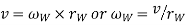
And velocity of precession 


Gyroscopic couple,
2. Effect of centrifugal couple
We know that centrifugal force,

This force acts horizontally through the centre of gravity along the outward direction,
Centrifugal couple,
Since the centrifugal couple has a tendency to overturn the vehicle, therefore total overturning couple,
 = Gyroscopic couple +centrifugal couple
We know that balancing couple =m.g.h.sin
The balancing couple acts in clockwise direction when seen from the front of the vehicle.
Therefore for stability, the overturning couple must be equal to the balancing couple, i.e.
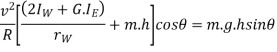
From this expression, the value of the angle of heel may be determined, so that the vehicle does not skid.


