UNIT2
UNIT2
UNIT2
Magnetic Circuit and Single Phase
Transformer
- Define Magnetic flux, Magnetic flux density, MMF.
Magnetic flux: the total no of lines of force in a magnetic field denoted by Ø and measured in Weber’s.
Magnetic flux density [B]= the flux per unit area measured in a plane perpendicular to the flux is defined as the flux density.
It is measured in tesla [T] and donated by B
B = Tesla / wb /
Magnetic motive force MMF: It is the force that is required for production of flux
MMF = No. Of turns x current
= N x I
= Ampere Turns
=AT
Magnetic field strength / intensity / magnetising force
It is the force experienced by a unit north poles placed at that point in the magnetic field Denoted by H
Measured in Newtown / wb or AT/n
H = N/wb
N/wb
H = 
2. Explain Coulombs Law of Electromagnetic.
1st Law- Like poles repels and unlike poles attract
2nd Law- is the force of attraction or repulsion 2 pole a magnetic field in directly proportional to the product of the field strength and inversely proportional to the square of the distance between then i.e. F X 
When K instant which depends upon nature of surrounding medium to the poles andm1 m2 are the pole strength.
Permeability- It is defined as the ability of a material to carry the flux lines. There are three Permeabilities
Absolute Permeability [μ]- It is defined as the ratio of magnetic flux density [B] in a particular medium to the magnetic field strength [H] which produces that flux density it is denoted by μ and measured in henry per meter
 H/M
H/M
Permeability of force space or vacuum:
It is ratio of magnetic flux density of force space or vacuum to the magnetic field strength it is denoted by μ0 and measured henry / meter
 H/M
H/M
The value of μₒ is always constant
μₒ= 4λ x 10-7 H/M
Relative Permeability: it is defined as the ratio flux density in a particular medium to the flux density in air or vacuum conditions the same magnet under identical conditions denoted by μ
 μ
μ (with same H)
Expression of μμ=  B = μH
μ₀ =  B₀ = μ₀H
Now μ
 μ
μ =
=
μ = μ₀μᵣ
Reluctance -it is defined as the opposition to the flow of flux in a material
Reluctance is denoted by S and measured in AT/wb or Siemens
S = ɺ/ μ₀μᵣₐ - AT/wb
It can also be defined as the ratio of (MMF) to the magnetic flux (Ø)
S =  - AT/wb
Permeance: it is defined as the reciprocal of reluctance the Permeance represents the property of magnetic material to allow the flux to pass through it
Permeance = - wb/AT
3. Compare Electrical and magnetic circuit.
Electrical | Magnetic
|
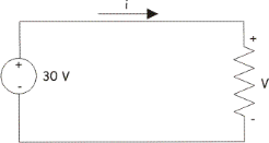 | 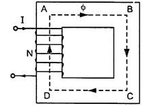 |
Current flow of electrons Unit- Ampere | Flux: magnetic lines of force Unit- Weber
|
I = 
| Ø = MMF/S
|
EMF: driving force for current | MMF driving force for flux: AT
|
Resistance: opposition to the Flow of current | Reluctance: opposition to the flow of flux |
R = ƍ  | s = 
|
I =  | ɸ 
|
Conductance =  | Permeance = 
|
Current density ʆ =  | Flux density B = 
|
Electric filed Intensity E =  | Magnetic field intensity H = 
|
Voltage drop V = IR | MMF Drop = Ø.S
|
It is closed path for current | It is closed path for flux
|
Kirchhoff’s current and voltage Law applicable to electric circuit | Kirchhoff’s flux and MMF laws are applicable to mag circuit
|
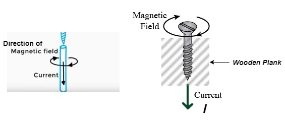
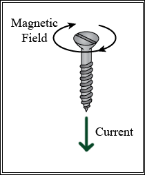
4. Write Cork Screw Rule.
Consider right-handed screw when this screw is to be inserted in a wooden plan it is to be rotated in a clockwise direction ɡȴ the direction of advancement of screw indicates the direction of current, then the circular rotational motion of screw indicates direction of magnetic field.
 5. Explain Magnetic field due to solenoid
(Large no of coils wounded on iron core)
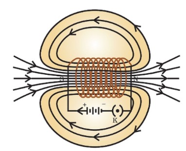
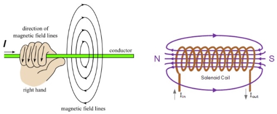
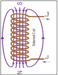
When the current is passed through the solenoid. The magnetic field is produced as show in above fig.
It is produced outside as well as inside the core of solenoid.
Note that direction of field is reversed due to current direction.
- Rules to find polarity of solenoid
- Right Hand Thumb Rule
2. Cork Screw Rule
- Force on current carrying conductor in a magnetic field.
It involves the interaction of magnetic field and current carrying conductor placed in it. The operation sequence is as follow
- Development of individual field
- Interaction of two magnetic fields
- Force exerted on the conduction
- Development of individual field
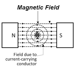
- Let a straight conductor is placed in the magnetic field produced by permanent magnet.
- Let current flowing through the conductor is out of the plane of the paper.
- The magnetic field produced by conductor is shown above
2. Interaction of two magnetic field
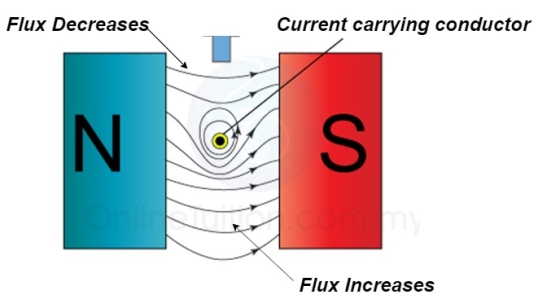
At the top flux lines produced by the magnet and conductor are in opposite direction to each other and hence cancel each other.
At the bottom individual fields are in same direction they will add each other.
3. Force excreted on the conductor
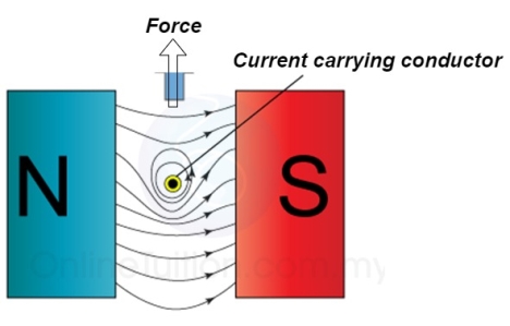
The lines of force on the bottom exert a force on the conductor in the upward direction as shown above.
Hence mechanical force is exerted on the conductor from high flux line area towards the low flux line area (top).
6. Explain Flemings left Hand Rule for direction of current (for Motor)
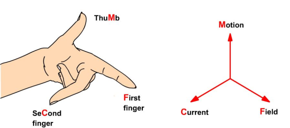
If the first 3 fingers of left hand are held mutually at right angle to each other. First finger indicates magnetic field middle finger indicates direction of current and thumb indicated force exerted.
The magnetically of force experienced by the current carrying conductor placed in a magnetic field is given by
F = B I ɺ sin Ɵ newton
Where F = Force exerted
B = Flux density
ɺ = length of conductor
I = current
Ɵ = angle between conductor and magnetic field.
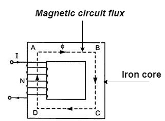
The magnetic circuit can be defined as the closed path traced by magnetic line of force such magnetic circuit is associated with different magnetic quantities such as MMF, flux, flux density, magnetic field strength
We know that H = 
And B = μ H
Put value of H
 B = μ x
But μ = μₒμ
 B = μ₀μ
But B =  = B x a
Ø =
7. Derivation of series magnetic current with air gap.
In series magnetic circuit flux  is same in each part of circuit
Consider a composite magnetic circuit made from different material of lengths ɻ1,ɻ2, and ɻ3cross sectional area a1, a2 And a3 and relative permeability’s  1 ,
1 , 2 ,
2 ,  3 resp. With an airgap of length ɻɡ
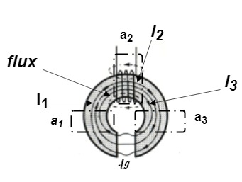
 Total reluctance S = S1 + S2+ S3 + Sg
We know that S = 
 +
+  +
+  +
+ 
But S =  and mmf = S x Ø
 mmf = Ø
 +
+  +
+  +
+  for air
Now B = 
 mmȴ =
mmȴ =  +
+  +
+  +
+ 
But B=μH
 H =
H =  =
= 
 Total mmȴ = H1 ɻ1+ H2 ɻ2 + H3 ɻ3 + Hƪɻƪ
8. Explain Faraday's law of electromagnetic induction.
- First law: whenever flux linkage with the coil changes an emf is induced in that conductor
- Second law: the magnitude of induced emf is equal to the rate of change of flux linkage
9. Explanation: suppose a coil has n turns and flux through it change from initial value of Ø1 to Ø2 in line t sec
Initial flux linkage = N Ø
Final flux linkage = NØ2
 Induced emfe =
Putting the above equation in differential form
e = rate of change of flux linkage

The direction of this induced emf is given by lenis law which states the polarity of induced emf is always such that it tends to set up a current which flow in such a direction so as to oppose the cause that produces it.

Whenever flux linking a conductor changes an emf is induced in it. This change in flux linkage can be trough about in the following 2 ways
- The conductor is moved in a stationary magnetic field in such a way that the flux linking is changes in magnitude.
The emf induced in this is called dynamically induced emf.
2. The conductor is stationary and magnetic field is moving or changing the emf induced in this way is called statically induced emf.
Statically Induce EMF:
This is technique of generating an emf but here neither the conductor nor the magnetic field are physically moved for EMF generation both are stationary.
The flux linkage taking place with conductor is changed by changing the magnitude of the current that produces magnetic field.
e.g. Transformers
10. Explain Self-Induced EMF in detail.
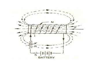
The EMF induced in coil due to change of its own flux linked with it is called as self-Induced EMF
The change in flux is brought by changing the current flowing in coil {using variable resister ‘R’ / or using ac supply}
Magnitude of self-Induced EMF
Consider a coil haring n Turns carrying a current I amperes
ɡȴ the current in the coil changes the flux linkage of the coil also changes which sets up a self-induced EMF in the coil
We know that
Ø x I
 Ø = K I

As  = K x I
Rate of flux linkage = K x rate of changes of current
 = K x
= K x
Now e = - N
Put value of  in above equation.
 e = - N k
 e = - N x
 x
x 
 K =
K = 
 e = - L
Where L =  = self Inductance
The property of coil that opposes any changes in the amount of current flowing through it is called as well Inductance.
Coefficient of self-Inductance:
Now L = 
We know that Ø = 
Ø = 
 now L =
  x
x 
 L =
L =  replacing Ø
 L =
L = 
S decreases L Increases
L is proportional to square of turn NL
11. Explain Mutually Induced EMF in detail.
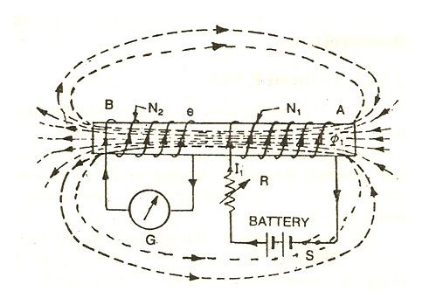
The emf induced in the coil due to change in current in the neighbouring coil is called as mutually induced EMF
Consider 2 coil 1 and 2 placed closed, adjacent to each other
Current  1 (Variable current) flows in coil 1, flux Ø1 is set upand a part ofthis flux (Ø2) links coil 2. The EMF induced in coil 2 is termed as mutually induced EMF whereas EMF induced in coil 1 is termed as self-induced EMF.
Mutually induced emf is given by
e2 = -N2 
We know that Ø2 x  1
1
Ø2=K 1and k =
Rate of change of flux in coil 2 = k x change in current in coil 1
 = K
= K 
Now e2 = - N2 
Replacing value of  in above eq. M
 e2 = - N2 K
 e2 = - N2 K
  x
x 
 e2= - M
Where
M =  mutual Inductance
- Coefficient of mutual Inductance
M = 
Now 


12. Explain working principle and construction of Single Phase transformer
Operating principle
It works on principle of mutual Induction ie “when 2 coil are inductively coupled and if current in one coil is changed uniformly then an emf get induced in another coil”
- When alternating voltage V1 is applied to primary winding am alternating current I1 flows in it producing alternating flux in the core.
- As per Faradays Law of Electromagnetic Induction 1 an emf E1 is induced in the primary winding E = N1

- The emf induced in the primary winding is nearly equal and opposite to applied voltage V1
- Assuming leakage flux to be negligible almost whole flux produced in primary winding links with secondary winding thence emf induced in the secondary winding E2 = N2

Construction
- There a 2 types of winding
- Concentric or cylindrical
- Sandwiched type
- Cylindrical
L.V. = low voltage H.V. = high voltage are mounted on same limb to minimum leakage .
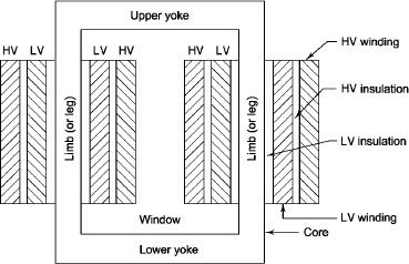
L.V. Winding placed inside and H.V. Winding placed outside with (proper insulation between the winding as it is easy to insulated L.V. Winding) than H.V. Winding.
2. Sandwiched
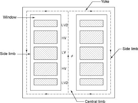
The H.V. And L.V. Winding are divided into no. Of small coils and there small windings are interleaved.
(the top and bottom winding are L.V. Coils because they are close to core)
- Transformer tank : wholes assembly of winding and core placed inside the Transformer tank (sheet metal tank) which is filled with Transformer oil or insulating oil which acts as an (insulator or coolant ) MCQ
- Transformer oil : (The function of oil is to remove efficiently the heat generated in core and in winding)
- Moisture should not be allowed which creeps the insulation which achieved by closed Transformer tank.
(To increase cooling surface are tubes or fins are provided)
- Conservator tank : above tank T/F tank there is one small tank in which same empty space is always provided above the oil level. (this space is required for oil to expand or contract due to temperature change) MCQ
However during contraction outside air can have moisture which will deteriorate the insulating properly of oil.
- Breather : the air goes in or out through the breather (To reduce the moisture content of their air . Same drying agents such as (silica gel or) calcium chloride) is used in the breather (The dust particles present in air are also removed by breather)
- Buccholz Relay : (for incipient (slowly increasing) faults
There is pipe connecting rain tank and conservator. On the pipe a protective device called Buccholz Relay is mounted.
When the Transformer is about to be faulty and draw range current the oil becomes very hot and decompose.
During this process different types of gases are liberated.(The Bucchoz Relay get operated by these gases) and gives an alarm to the operator. ɡȴ the fault continues to persist then there lay will trip off main circuit breaker to protect the Transformer.
- Explosion Vent :
An explosion Vent or relief value is the bent-up pipe filled on the main tank.
(The explosion vent consist of aluminium of oil) when the T/F becomes faulty the cooling oil get decomposed and various types of gases are liberated
(ɡȴ the gas pressure exodus certain level then the aluminium of oil (diagram) in explosion vent will burst) to release pressure. They will save main tank from getting damaged.
- Single phase transformer -
(Symbol and principal of operation)
It is a static device which can transfer electrical energy from one ac circuit to another ac circuit without change in frequency
It can increase or decrease the voltage but with corresponding decrease or increase in current
It works on Principle 
“Mutual Induction”
A major application of transformer is to increase voltage before transmitting electrical energy over a long distance through conductors and to again reduce voltage at place where it is to be used.
Symbol
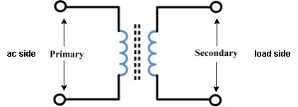
- Primary winding : (ac supply side) For MCQs
The winding which is connected to supply is called primary side
2. Secondary winding : (load side) for MCQs
The winding which is connected to load is called as secondary winding