UNIT 4
Poly-Phase Circuits
- Explain the Generation of three phase voltages.
- Poly phase one which produces many phases simultaneously
- Instead of saying poly phase we use 3 ɸ supply there for 3 ɸ system
- Generation of electrical supply is 3 ɸ only using alternator (AC generator ) by 3 separate winding placed 1200 a part from each other one winding for I phase
 3 windings
3 phase =  = 1290 apart each winding
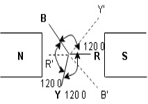
Here R is the reference phase globally in generation of 3 Ø ac
Ø = 0
Y is the 2nd phase generated and placed apart from R phase Ø = -1200
B is the 3rd phase generated and placed apart from R phase Ø = -2400
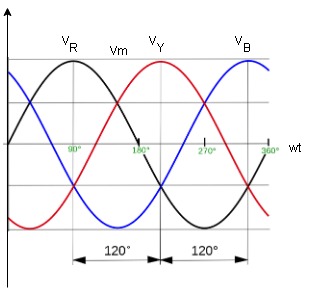
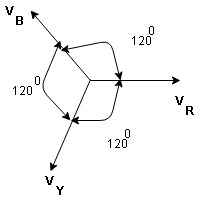
- Phasor Diagram :
Equation
VR = Vm Sin wt
VY = Vm Sin (wt-1200)
VB = sin (wt – 2400)
Or VB = Vm sin (wt + 1200)
2. Write the advantages of 3 Ø system over single phase.
- More output : for same size the output of 3Ø machine is always higher than single 1 Ø phase machine.
- Smaller size : for producing same output the size of 3 phase machine is always smaller than of single phase machine
- 3 phase motor are self starting as the 3 Ø ac supply is capable of producing a rotating magnetic file when applied are self starting 1 Ø motor need additional starter winding
- More power is transmitted : in the transmitted system it is possible to transmitted more power using 3 Ø system rather than 1 Ø system, by using conductor of same cross sectional .
- Smaller cross sectional area of conductor
ɡȴ same amount of power is to transmitted than cross sectional area of conductor used for 3 Ø system is small as compared to that for single Ø system.
3. Write and explain types of loads in detail.
Types of loads
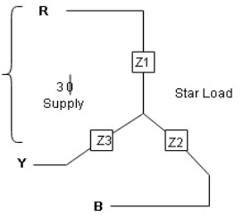
- Star connection of load
- Delta connection of load
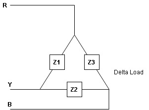
- Balanced load: balanced load is that in which magnitude of all impedance connected in the load are equal and the phase angle of them are also equal
Ie Z1  Z2
Z2  Z3 then it is unbalanced load
4. Explain Line values and phase Values.
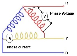
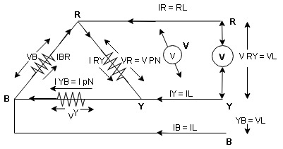
- Line Values: ɡȴ RYB are supply lines then the voltage measured between any 2 Line is called as line voltage and current measured in the supply line is called as line current.

2. Phase Value: the voltage measured across a single winding or phase is called as phase voltage and the current measured on the single winding or phase is called as line current.
5. Derive Relation between line value and phase value of voltage and current for balanced (ʎ) star connected load (load can be resistive, Inductive or capacitive)
For capacitive load
Consider a 3 Ø balanced star connected balanced load capacitive
6. Line Value
Line voltage = VRY = VYB = VBR = VL
Line current = IR = IY = IB = IL
Phase value
Phase voltage = VRN = VYN = VBN = Vph
Phase current = VRN = VYN = VBN = Vph
Since for a balanced star connected load the line current is the same current flowing in the phase  the line current = phase current IR = IY = IB = IRN = IBN = IYN
 dor star connected load IN = Ipn
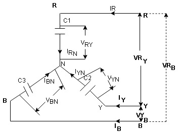
7. Since the line voltage differ from phase voltage we can relate the line value of voltage with phase value of voltage
Referring current diagram
 =
=  +
+ 
Bar indicates vector addition
 =
= 
 =
=  -
-  …..①
…..①
Instead of writing  or
or  we can write VR and VY for practical purpose
Similarly other line voltage can be writing as follows.
(Resultant)
 =
=  -
-  …..②
…..②

 =
=  -
- 
8. Phasor Diagram :
Consider equation …..①
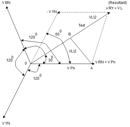
NOTE : We are getting resultant line voltage by subtracting phase voltage  take phase voltage at reference phase as shown
Cos 300 = 
 =
= 
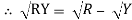
 VL =
VL = 
9.  phase for ʎ connected capacitive balance load

10. relation between line value and phase value of voltage and current for a balance ( ) delta connected inductive load
Consider a 3 Ø balance delta connected inductive load
11. line values
Line voltage = VRY = VYB = VBR = VL
Line current = IR = IY = IB = IL
Phase value
Phase voltage = VRN = VYN = VBN = Vph
Phase current = VRN = VYN = VBN = Vph
12. since for a balance delta connected load the voltage measured in line and phase is same because their measuring points are same
 for balance delta connected load VL = Vph
 VRV = VYB = VBR = VR = VY = VB = VL = VPh
13. since the line current differ from phase current we can relate the line and phase values of current as follows
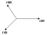
14. apply KCL at node R
IR + IRY= IRY
 IR = IRY - IRY … ….①

Line phase
Similarly apply KCL at node Y
IY + IYB = IRY … ….②
Apply KCL at node B
IB + IBR = IYB … ….③
15. Phasor Diagram
Consider equation ①
Note : we are getting resultant line current IR by subtracting 2 phase currents IRY and IBR  take phase currents at reference as shown
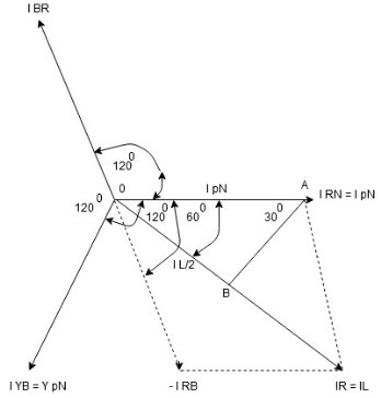
Cos 300 =
 =
= 
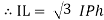
16. Complete phases diagram for delta connected balanced Inductive load.
Phase current IYB lags behind VYB which is phase voltage as the load is inductive
17. Power relation for delta load star power consumed per phase
PPh =VPhIPh Cos Ø
For 3 Ø total power is
PT= 3 VPhIPh Cos Ø …….①
For star
VL and IL = IPh (replace in ①)
 PT = 3
  IL Cos Ø
 PT = 3
  VL IL Cos Ø – watts
For delta
VL =VPhand IL =  (replace in ①)
PT = 3VL
= 3VL  Cos Ø
Cos Ø
 PT
PT VLIL Cos Ø – watts
Total average power
P =  VLIL Cos Ø – for ʎ and
  load
load
K (watts)
Total reactive power
Q =  VLIL Sin Ø – for star
  delta load
K (VAR)
Total Apparent power
S =  VL IL – for star
  delta load
K (VA)
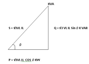
18. Power triangle
19. Relation between power
In star and power in delta
Consider a star connected balance load with per phase impedance ZPh
We know that for
VL = VPhandVL=  VPh
VPh
Now IPh = 
 VL = =
And VPh=
 IL =
IL = ……①
……①
Pʎ =  VL IL Cos Ø ……②
Replacing ① in ② value of IL
 Pʎ =
Pʎ =  VL IL
VL IL  Cos Ø
Cos Ø
 Pʎ =
Pʎ =  ….A
….A
20. Now for delta
IPh =
 IPh = =
And IL = IPh
IPh
 IL =
IL = X
X  …..①
…..①
P =
=  VL IL Cos Ø ……②
Replacing ② in ① value of IL
P =
=  Cos Ø
Cos Ø
 P
P =
=  …..B
…..B

Pʎ from …A
 …..C
…..C
 =
=  P
P
We can conclude that power in delta is 3 time power in star from …C
Or
Power in star is  time power in delta from ….D
6. Write the Steps to find S.
- Calculate VPh from the given value of VL by relation
For star VPh = 
For delta VPh= VL
2. Calculate IPh using formula
IPh = 
3. Calculate IL using relation
IL = IPh - for star
IL = IPh - for delta
4. Calculate P by formula (active power)
P =  VL IL Cos Ø – watts
5. Calculate Q by formula (reactive power)
Q =  VL IL Sin Ø – VAR
6. Calculate S by formula (Apparent power)
S =  VL IL– VA


