UNIT 4
Engineering Mechanics
Questions
Question 1) Difference between Frame and Truss?
Answer 1)
Truss
| Frame
|
Question 2) Two identical spheres having weight 1000 N are kept in a container as shown in figure. Find the reaction at all contact surfaces.
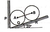
 Answer 2)
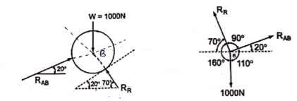
 Consider the free body diagram of sphere B as shown below:
By lami’s theorem


 RRR = 939.69 N

 = RAB
= RAB
Now consider FBD of sphere A
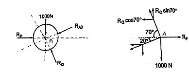
∑Fx = 0
-RB cos 20 – RQ cos 70 + Rp = 0
-342.02 cos 20 – RQ sin 70 + Rp = 0
 Rp = 321.39 + 0.34 RQ -------(1)
∑ fy = 0
RQ sin 70 – 342.02 sin 20 – 1000 = 0
 RQ = 1188.66 N - put in equation (1)
 Rp = 725.5 N
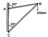
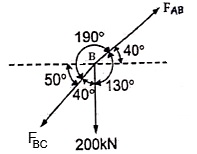
Question 3) two members AB & BC are supporting a load of 200 kN as shown in figure. Find the forces developed in the members AB & BC
 Answer 3)
 Consider the free body diagram of joint B as shown in figure
Assume that member BC is in compression & AB is in tension. By using Lami’s theorem at B,


 FAB = -740.33 kN
-ve sign indicates that member AB is not in Tension but is in compression.
Now,


-ve sign indicates that member BC is not in compression but in tension.
Question 4) A Sphere of weight 200 N rests on a smooth inclined plane. A sphere is kept in equilibrium by means of cable as shown. Find tension in cable and reaction.
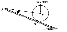
 Consider the FBD of sphere B as shown in figure above.
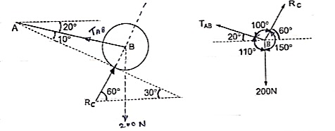
Applying lami’s theorem, we have


 RC = 190.84 N


 TAB = 101.54 N
Question 5) Explain Method of joints?
Answer 5)
If a truss is in equilibrium, then each of its joints must also be in equilibrium. Procedure - starts with a joint that has no more than two unknown forces
- Establish the x and y axis; - At this joint, ∑ Fx = 0 and ∑ Fy = 0;
- After finding the unknown forces applied on this joint, these forces become the given values in the analysis of the next joints.
The joints with external supports always connect with two truss members. Thus many times, the analysis starts from analysing the supports. Therefore very often the analysis begins with finding the reaction forces applied at the supports.
- Pay attention to symmetric systems and zero force members. Identification of these special cases sometimes will make the whole analysis way easier
For solving simple truss example using method of joints we will follow the below procedure.
Draw the free body diagram which minimum one known and 2 unknown force.
Use one of the two methods described above for establishing the sense of an unknown force.
Draw x and y axed such that we can easily solve for x and y components and then apply the two force equilibrium equations and Solve for the two unknown member forces and verify their correct sense.
Question 6) Explain Method of sections?
Answer 6)
If a truss is in equilibrium, then whichever section of the truss being considered must also be in equilibrium.
Finding the reaction forces: Make a cut through the members where the unknown forces are applied; - Establish equilibriums for one of the sections:
∑ Fx = 0; ∑ Fy = 0; ∑M = 0;
If your result comes out to be negative, then it means you assumed a wrong direction of the force.
Application - The method of sections is commonly used when the forces in only a few particular members of a truss are to be determined;
The method of sections is always used together with the method of joints to analyse trusses.
For solving simple truss example using method of sections we will follow the below procedure.
Make a cut in section where forces are to be determined.
Initially determine support reactions.
Draw the free-body diagram of that segment of this type of truss which is sectioned with minimum forces.
Unknown member forces can be found by above mentioned methods.
Moments should be summed about a point that lies at the intersection of the lines of action of two unknown forces, so that the third unknown force can be determined directly from the moment equation.
If two of the unknown forces are parallel, forces may be summed perpendicular to the direction of these unknowns to determine directly the third unknown force
Question 7) what is concurrent force?
Answer 7)
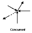
A concurrent coplanar force system is a system of two or more forces whose lines of action ALL intersect at a common point. However, all of the individual vectors might not actually be in contact with the common point. These are the most simple force systems to resolve with any one of many graphical or algebraic options.
Question 8) Explain parallel force?
Answer 8)
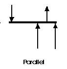
A parallel coplanar force system consists of two or more forces whose lines of action are ALL parallel. This is commonly the situation when simple beams are analysed under gravity loads. These can be solved graphically, but are combined most easily using algebraic methods.
Question 9) what is non-concurrent non-parallel?
Answer 9)
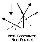
The last illustration is of a non-concurrent and non-parallel system. This consists of a number of vectors that do not meet at a single point and none of them are parallel. These systems are essentially a jumble of forces and take considerable care to resolve.
Question 10) Explain free body diagram?
Answer 10) If a body is shown with all external forces acting on it so that the body is in equilibrium, such diagram is called as free body diagram.
To draw the free body diagram, we have to remove all the restrictions like wall, floor, hinge, any other support and replace them by reactions which these support extents on the body.
Ex – 1) Draw FBD of a bar supported and loaded as shown below.

2) Draw FBD of sphere supported as shown below.
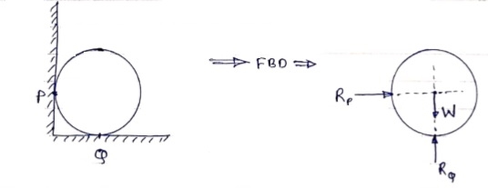
A free-body diagram is a sketch of an object of interest with all the surrounding objects stripped away and all of the forces acting on the body shown. The drawing of a free-body diagram is an important step in the solving of mechanics problems since it helps to visualize all the forces acting on a single object. The net external force acting on the object must be obtained in order to apply Newton's Second Law to the motion of the object.
A free-body diagram or isolated-body diagram is useful in problems involving equilibrium of forces.
Free-body diagrams are useful for setting up standard mechanics problems.
