UNIT 2
MEASUREMENT
QUESTION
Question 1) Ways to Reduce Measurement Error?
Answer 1)
- Double check all measurements for accuracy. For example, double-enter all inputs on two worksheets and compare them.
- Double check your formulas are correct.
- Make sure observers and measurement takers are well trained.
- Make the measurement with the instrument that has the highest precision.
- Take the measurements under controlled conditions.
- Pilot test your measuring instruments. For example, put together a focus group and ask how easy or difficult the questions were to understand.
- Use multiple measures for the same construct. For example, if you are testing for depression, use two different questionnaires.
Question 2) Explain Radiation Pyrometers?
Answer 2)
No contacting temperature measurement can be achieved through the use of radiation, or optical, pyrometers. The high temperature limits of radiation pyrometers exceed the limits of most other temperature sensors. Radiation pyrometers are capable of measuring temperatures to approximately 4000·C without touching the object being measured.
Principles of Radiation Pyrometer
Temperature measurement with radiation pyrometers is based on the fact that all objects emits radiant energy. Radiant energy is emitted in the form of electromagnetic waves, considered to be a stream of photons traveling at the speed of light. The wavelengths of radiant energy emitted by a hot object range from the visible light portion (0.35 to 0.75 microns) to the infrared portion (0.75 to 20 microns) of the electromagnetic spectrum.
In the visible light portion of the spectrum, radiant energy appears as colors. The expression "red hot" is derived from the fact that a sufficiently hot object will emit visible radiation. Common examples include a piece of red hot steel and a tungsten filament lamp. Radiation pyrometers measure the temperature of an object by measuring the intensity of the radiation it emits. The intensity and wavelength of the radiation emitted by an object depends on the emittance and the temperature of the object. Emittance is a measure of an object's ability to send out radiant energy. It is inversely related to reflection of the object's surface. Since emittance will differ from one object to another, a standard, called a blackbody, is used as a reference for calibrating radiation pyrometers and serves as the basis for the laws that define the relationship of the intensity of radiation and wavelength with temperature. A blackbody is an object having a surface that does not reflect or pass radiation. It is considered a perfect emitter because it absorbs all heat to which it is exposed and emits that heat as radiant energy.
The intensity of radiant energy increase as temperature increases. The peak of radiation moves to lower wavelengths as temperature increases. In the visible light portion of the spectrum, this effect can be seen by the change in colour of heated metals. They change from red to yellow to white to blue-white as temperature increases.
Types of Pyrometers
A radiation pyrometer consists of optical components that collect the radiant energy emitted by the target object, a radiation detector that converts the radiant energy into an electrical signal, and an indicator that provides a readout of the measurement. The optical pyrometer, also known as the brightness pyrometer, requires manual adjustment based on what is viewed through a sighting window. Because it relies on what can be seen by the human eye, an optical pyrometer is designed to respond to very narrow band of wavelengths that fall within the visible light portion of the electromagnetic spectrum.
Another type of pyrometer that is commonly used for industrial temperature measurement is the total radiation pyrometer. A total radiation pyrometer responds to wavelengths in both the visible and infrared portions of the spectrum. Ideally, it would measure all wavelengths within this range. However, the glass window filters out some wavelengths. Any gases or vapors between the target and pyrometer will also attenuate certain wavelengths. Total radiation pyrometers are based on the Stefan-Boltzmann law which states that total radiation is proportional to the fourth power of temperature. These pyrometers are calibrated using a blackbody and therefore measure the temperature based on the total radiation a blackbody would emit.
Pyrometer Accuracy
One technique for ensuring that emitted radiation rather than reflected radiation is being observed is to drill a hole in the target object and aim the pyrometer into the hole. It is recommended that the depth of the hole be about five times its diameter. Measurement accuracy can also be affected by the presence of gases or vapors between the target and pyrometer. Gases and vapours can filter out some radiation wavelengths. One technique for resolving this problem is to use fans to disperse any gases or fumes. A film of dirt on the viewing window or lens will also affect measurement accuracy. In some applications, it may be necessary to use a purge to prevent soot or other particles form being deposited on the viewing window or lens.
Question 3) How to choose the right type of pressure sensor?
Answer 3)
Bridge-based or piezo resistive sensors are the most common types of sensor because of their simple construction and durability. This translates to lower cost and makes them ideal for higher channel systems. In general, foil strain gages are used in high-pressure (up to 700M Pa) applications. They also have a higher operating temperature than silicon strain gages (200 °C versus 100 °C, respectively), but silicon strain gages offer the benefit of larger overload capability. Because they are more sensitive, silicon strain gages are also often preferred in low-pressure applications (~2k Pa).
Capacitive and piezoelectric pressure transducers are generally stable and linear, but they are sensitive to high temperatures and are more complicated to set up than most pressure sensors. Piezoelectric sensors respond quickly to pressure changes. For this reason, they are used to make rapid pressure measurements from events such as explosions. Because of their superior dynamic performance, piezoelectric sensors are the least cost-effective, and you must be careful to protect their sensitive crystal core.
Conditioned sensors are typically more expensive because they contain components for filtering and signal amplification, excitation leads, and the regular circuitry for measurement. This is helpful for lower channel systems that do not warrant a dedicated signal conditioning system. Because the conditioning is built in, you can connect the sensor directly to a DAQ device as long as you provide power to the sensor in some way. If you are working with nonconditioned pressure bridge-based sensors, your hardware needs signal conditioning. Check the sensor’s documentation so that you know whether you need additional components for amplification or filtering.
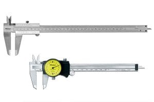
Question 4) What is the difference between a dial caliper and a vernier caliper?
Answer 4) Dial callipers and vernier callipers provide measurements of the same accuracy. The primary difference between the two tools is the way these measurements are displayed. The dial on the dial caliper makes it an easier tool to read. However, many people are used to the more traditional vernier scale and so prefer to use the vernier caliper.
The dial on the dial caliper makes it an easier tool to read. However, many people are used to the more traditional vernier scale and so prefer to use the vernier caliper.

Question 5) why we Use a Micrometer?
Answer 5)
We use a micrometer when a very precise measurement is needed. There are several different designs, depending on what needs to be measured. This could be the size of a pipe, tool or object from the outside. This could be the inside width of a pipe, bearing or another hollow object. Or this could be the depth of a hole or recess.
These are the tools you will reach for when accuracy is the most important factor. This is frequently true for machines with moving parts. Parts that move in and out of each other, like a piston, for example, need to remain in a steady, straight line. If these parts have even the smallest bit of sway, they can begin to fail. This is also true in other applications, such as the use of bearings. Other applications that require the most exact measurement are pipe fittings—especially if the pipe will be moving gases with very small and light molecules, like helium. Micrometers are also the preferred tool when measuring the thickness of items like sheet metals.
Question 6) How to Read a Micrometer?
Answer 6)
It is important to check if the micrometer is English or metric before using it for measurements. Make sure you are using a tool that has the same unit of measure as whatever you are already working with.
Once the micrometer is rotated into the proper measurement, the measurement can be taken. This requires adding together numbers found on the spindle and thimble which will give you the accurate measure. How to find the numbers you want will vary depending on the type and design of the micrometer. Instructions on how to read your micrometer will come from the manufacturer with your tool.
Question 7) Discuss advantage disadvantage application of dial gauge?
Answer 7)
Application of Dial Indicators:
Dial indicators are used in enormous ways by engineers, some of them are given below briefly:
- Dial indicators are used to align a workpiece in a machine. Such as, in the case of EDM, grinding machine, lathe machine, and milling machine.
- The tools are also used to check out the runout of the spindle in a machine tool.
- Workpiece can be aligned in the spin fixture by the help of Dial Indicators.
- It is also used to measure surface roughness.
- Dial indicators are used to measure parting lines in injection molding.
- It is useful to measure pit depth in EDM (Moldmakingresource, 2020).
- Dial indicators are efficient to measure height difference on a surface plate.
- Along with that, the tools are also very efficient to align a fixture in 5 axes milling machines.
- Dial indicators are used by engineers to inspect the precision of a workpiece in a grinding machine.
Advantages of Dial Indicators:
Some of the most effective advantages of Dial Indicators are given below:
- Dial indicator is the most flawless tool in taking linear measurements.
- The tool is very efficient to assure the quality of a workpiece
- Due to small tolerances, the size of the tool is very compact and thus, it can be used seamlessly in mass production.
- Dial indicator is also useful in dimension control.
- Moreover, Dial Indicators are also be used to measure several deviations by aligning with some other attachments.
- Out of roundness, the amount of tapper can also be measured efficiently by Dial Indicators.
Disadvantages of Dial Indicators:
Here are some disadvantages of dial indicators:
- The precision of Dial Indicators often lost due to the vibration of machinery.
- Space constraints can lead to installing the tool at an angle due to which precision of the measuring device lost.
- Another crucial disadvantage of the tool is the parallax effect.
- End float can act as a devil for Dial Indicators. In the case of journal bearings and sleeve bearing, some amount of axial play seems to be incorporated. Therefore, its impact on the accuracy level of Dial Indicators.
Question 8) Explain the Types Of Sine Bar:
Answer 8)
Different Sine bars are available according to the purpose of its use and method of application. Some types of sine bar are:
1) Sine centre:
This type of sine bar is used to measure angles of conical objects that have male and female parts. Sine centre cannot measure an angle of more than 45 degrees.
2) Sine Table:
Sine Table is a special type of sine bar which is large and wide. This sine bar has a mechanism for locking it in place after positioning which is used to hold the workpiece during operations.
3) Compound Sine Table:
A compound sine table is used to measure the angles of large workpieces which cannot be measured using a simple sine bar. In the compound sine table, two sine tables are placed one over the other at right angles. These tables can be twisted to get the required alignment.
Question 9) writes sine bar usage?
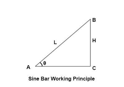
Answer 9) To measure a known angle or locate any work to a given angle:
- Always use a perfectly flat and clean surface plate.
- Place one roller on the surface plate and the other roller on the slip gauge block stack of height H.
- Let the sine bar be set to an angle ϴ.
- Then sin(ϴ) = H/L, where L is the distance between the centre
- Thus knowing ϴ, H can be found and any work can be set out at this angle as the top face of the sine bar is inclined at angle ϴ to the surface plate.
Question 10) Explain Working Principle of Sine Bar?
Answer 10)
The principle of operation of the sine bar is based on the law of trigonometry.
If one roller of sine bar is placed on the surface plate and the other roller is placed on the height of slip gauges, then the structure formed by the sine bar, surface plate, and slips gauges forms a triangle. The hypotenuse of this triangle is the sine bar, perpendicular is formed by combination of slip gauges and the surface plate is the base.
Suppose the height of slip gauges is H and the length of the sine bar is L, then sine ratio the angle theta will be H divided by L.
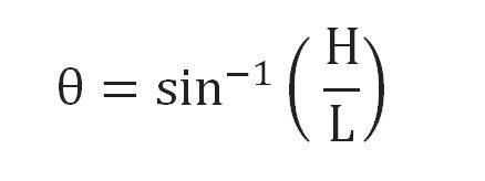
Now the angle θ can be calculated as sin inverse of H divided by L.


Construction Of Sine Bar:
A sine bar consists of a ground body made with hardened material like steel. Two rollers are attached at the end of the steel bar. The rollers are of equal diameters and axes of these rollers are parallel to each other.
The top of the steel bar is parallel to the line through the centres of two rollers.
The length of the sine bar is equal to distance between centre of two rollers.
This length of the sine bar is either 100mm, 200mm or 300 mm.This length is very precise and accurate. Relief holes are provided just to minimize the weight of sine bar.
Only a sine bar alone can’t be used for measurement of angles of a component. The sine bar is always used in association with slip gauges and height gauge for measurement of the angles.