Question bank
Unit 2
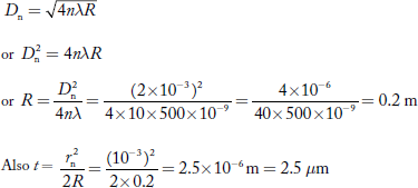
Q 1 Newton’s rings are observed in the reflected light of wave length 5900 Å. The diameter of 10th dark ring is 0.5 cm. Find the radius of curvature of the lens used.
Answer:
The given data are
Wave length of light (λ) = 5900 Å= 5900 × 10–10 m
Diameter of 10th Newton’s dark ring (D10) = 0.5 cm = 0.5 × 10⁻² m
Radius of curvature of lens (R) =?
Formula is D2n = 4nλR

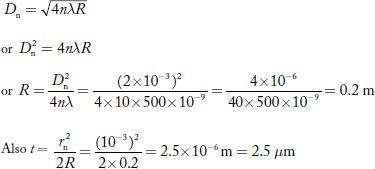
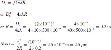
Q 2 Calculate the thickness of air film at the 10th dark ring in a Newton’s rings system, viewed normally by a reflected light of wave length 500 nm. The diameter of the 10th dark ring is 2 mm.
Answer:
Given data are
Wave length of light (λ) = 500 nm = 500 × 10–9 m
Number of the dark ring viewed (n) = 10
Diameter of 10th dark ring (D10) = 2 mm = 2 × 10⁻³ m
Radius of 10th dark ring 
Thickness of air film (t) =?
Condition for dark ring is
Q 3 What are condition of interference?
Answer:
Condition for Interference
To obtain the stable interference pattern the following conditions are required
Condition for Sustained Interference Pattern
a. The two interfering waves should be coherent i.e., both light waves are in same phase or maintain constant phase difference between them.
b. The source must be monochromatic
c. Both the wave must be in same set of polarization.
Condition for observation of fringes
a. The distance between the coherent sources be small
b. The distance between the source and screen must be large
Condition for Good Contrast
a. The amplitude of the both interfering waves be the same or very nearly same.
b. The sources must be narrow
c. The interfering angle should be very small or both travel in the same direction.
Q 4 Explain the Rayleigh criterion for limit of resolution?
Answer:
Rayleigh Criterion of Resolution
Statement: Two sources are resolvable by an optical instrument when the central maximum of one diffraction pattern falls over the first minimum of the other diffraction pattern and vice versa.
For example:
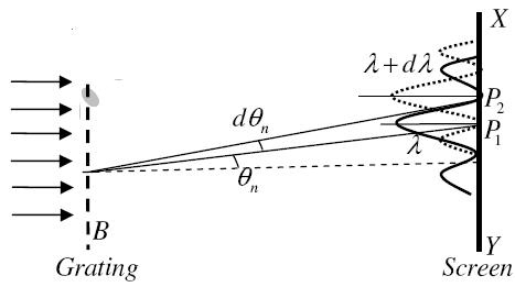
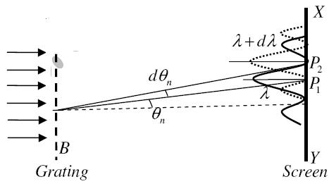
Let us consider the resolution of two wavelengths and by a grating. When the difference in wavelengths is smaller and such that the central maximum of the wavelength coincides with the first minimum of the other as shown in figure, then the resultant intensity curve is as shown by the thick curve. The curve shows a distinct dip in the middle of two central maxima. Thus, the two wavelengths can be distinguished from one another and according to Rayleigh they are said to be “Just Resolved”.
If the difference in wavelengths is such that their principal maxima are separately visible, then there is a distinct point of zero intensity in between the two wavelengths. Hence according to Rayleigh, they are said to be “Resolved”.
When the difference in wavelengths is so small that the central maxima corresponding to two wavelengths come still closer as shown in figure, then the resultant intensity curve is quite smooth without any dip. This curve is as if there is only one wavelength somewhat bigger and stronger.
Hence according to Rayleigh, the two wavelengths are “Not Resolved”.
Thus, the two spectral lines can be resolved only up to a certain limit expressed by Rayleigh Criterion.

Q 5 Explain Huygens principal of wave?
Answer:
Huygens' Principle
In 1678 Huygens proposed a model where each point on a wavefront may be regarded as a source of waves expanding from that point. The expanding waves may be demonstrated in a ripple tank by sending plane waves toward a barrier with a small opening. If waves approaching a beach strike a barrier with a small opening, the waves may be seen to expand from the opening.

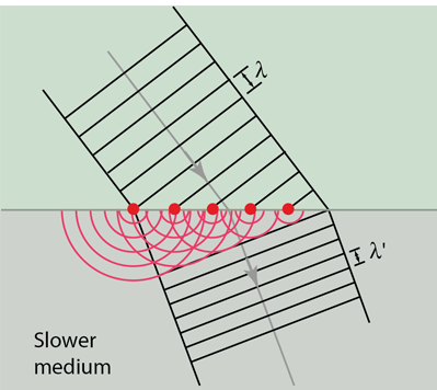
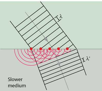
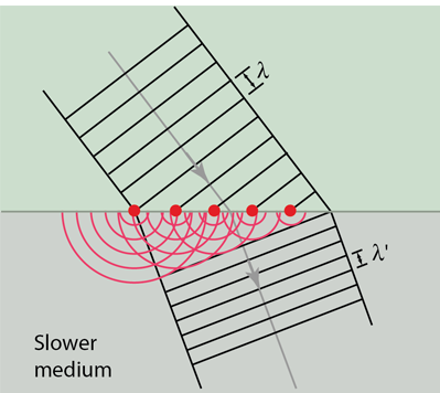
Huygens' principle provides a convenient way to visualize refraction. If points on the wavefront at the boundary of a different medium serve as sources for the propagating light, one can see why the direction of the light propagation changes.
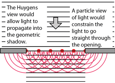
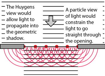
The Huygens' principle view permitted a visualization of how light could penetrate into the geometric shadow in a way that the particle view could not
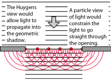
Though helpful in establishing a wave view rather than a particle view of light for ordinary optics, Huygens' principle left a number of unanswered questions. For example, with its view of each point on a wavefront as a source, it gave no explanation of why it didn't propagate backward as well as forward.
Q 6 Give brief explanation of young double slit experiment?
Answer:
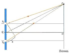
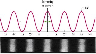
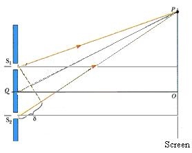
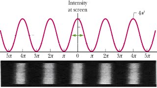
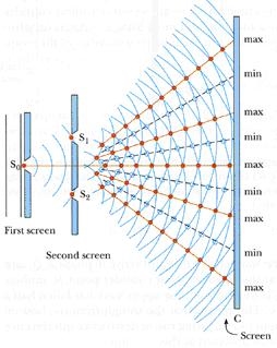
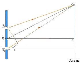
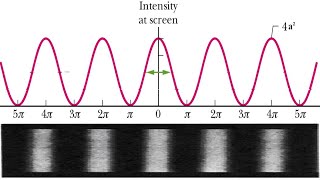
Young allowed the sunlight to pass a through a pin hole So on first screen followed by S1 and S2 at some distance on second screen as shown in figure. On the screen he observed few coloured bright and dark bands. To increase the brightness of bands the pin holes S1 and S2 are replaced by narrow slits and to increase the number of fringes sunlight is replaced by monochromatic source. Finally, the interference pattern consists of equally spaced bright and dark fringes are obtained.

Explanation of Experiment
Spherical wave came out as the sunlight passes through the pin hole So, (as per Huygens’s wave theory), the radii of these waves increases as they move away from So, when these spherical waves reaches the second screen again spherical waves came out from S1 and S2, these waves move away from S1 and S2 and hence they superimpose on each other. At the point where wave crest (or trough) of one wave fall on the wave crest (trough) of other, the resultant amplitude is maximum (maximum intensity, as I = A2) and where the wave crest of one fall on the wave trough of other, the resultant intensity is minimum. In this way large number of dark and bright bands are formed on screen.
Condition for Constructive and Destructive Interference
Consider that S1 and S2 are two coherent sources. If a1 and a2 are the amplitude of wave from S1 and S2 respectively. d is the phase difference between the two waves in reaching point P on the screen.
The displacement of the two waves can be given as
 .........................(2.1)
 ...........(2.2)
According to the theory of superposition, the resultant displacement


Or 
Say  ..................(2.3)
and  ................................(2.4)
Substituting these values


Squaring and adding eq 2.3 and 2.4, the resultant amplitude at P, will be

 ...................(2.5)
Therefore, the intensity at point P (I = R2)
 ..................(2.6)
Condition for Constructive Interference (Maxima)
Intensity at P will be maximum if 
i.e. 
Or Path Difference  ........................(2.7)


Q 7 Two coherent sources whose intensity ratio is 36:1 produce interference fringes. Deduce the ratio of maximum intensity to minimum intensity.
Answer:
Intensities ratio of coherent sources = a21 : a22 = 36: 1
∴ a1 : a2 = 6: 1
Minimum intensity of the interference fringe = (a1 – a2)2
= (6 – 1)2 = 25
Maximum intensity of the interference fringe = (a1 + a2)2
= (6 + 1)2 = 49
The ratio of maximum intensity to minimum intensity = 49 : 25 ≈ 2 : 1
Q 8 Define following?
1 Diffraction Grating
2 Resolving power
Answer:
It is defined as the capacity of a grating to form separate diffraction maxima of two wavelengths which are very close to each other
It is measured by  where
where  is the smallest difference in two wavelengths which are just resolvable by grating and
 is the wavelength of either of them or mean wavelength.
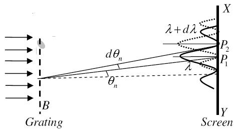
Let AB represent the surface of a plane transmission grating having grating element (e+d) and N total number of slits. Let a beam of light having two wavelengths  and
and  is normally incident on the grating. Let P1 is nth primary maximum of a spectral line of wavelength
  at an angle of diffraction
  and P2 is the nth primary maximum of wavelength
  at diffracting angle
According to Rayleigh criterion, the two wavelengths will be resolved if the principal maximum  of nth order in a direction
  falls over the first minimum of nth order in the same direction
  . Let us consider the first minimum of l of nth order in the direction
  as below.
The principal maximum of  in the
  direction is given by
 ...
...
The equation of minima is  where m takes all integers except 0, N, 2N, …, nN, because for these values of m, the condition for maxima is satisfied. Thus, first minimum adjacent to nth principal maximum in the direction
 can be obtained by substituting the value of ‘m’ as (nN+1). Therefore, the first minimum in the direction of
  is given by

 ..
..
The principal maximum of  in direction
  is given by
 ..
..
Dividing eqns, we get


 .
.
Thus, the resolving power is directly proportional to
(i) The order of the spectrum ‘n’
(ii) The total number of lines on the grating ‘N’
Q 9 What is Mach-Zehnder interferometer?
Answer:
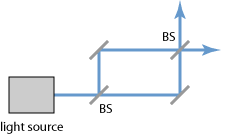
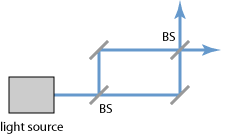
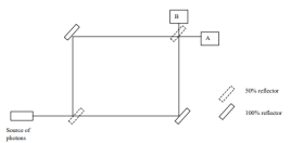
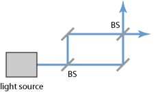
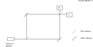
The Mach–Zehnder interferometer was developed by the physicists Ludwig Mach and Ludwig Zehnder. As shown in Figure 1, it uses two separate beam splitters (BS) to split and recombine the beams, and has two outputs, which can e.g. Be sent to photodetectors. The optical path lengths in the two arms may be nearly identical (as in the figure), or may be different (e.g. With an extra delay line). The distribution of optical powers at the two outputs depends on the precise difference in optical arm lengths and on the wavelength (or optical frequency).
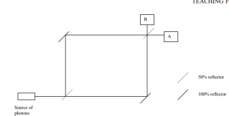

The upper path picks up the following phase shifts on the way to detector A: π at the first reflection, π at the second (100%) reflection, nothing at the transmission, 2πl1/λ for the distance travelled, and 2πt/λ for the extra phase picked up in traversing the glass substrates where the wavelength is reduced. This gives a total of

The lower path, also on its way to A, picks up a phase shift of π off the 100% reflector, π at the second beam splitter, a phase shift of 2πl2/λ for the distance travelled, and an extra phase shift of 2πt/λ from passing through the glass substrate at the first beam splitter. The phase difference between the two paths is

Where δ is the phase shift due to the difference in the path lengths. Similarly, we can calculate the phase difference between the two paths on their way to detector B. We obtain

If the interferometer is well aligned, the path length difference can be adjusted (e.g. By slightly moving one of the mirrors)
Q 10 In a Newton’s ring experiment, the diameter of the 5th ring is 0.30 cm and diameter of the 15th ring is 0.62cm. Find the diameter of the 25th ring
Answer:
Diameter of Newton’s 5th ring = 0.30 cm
Diameter of Newton’s 15th ring = 0.62 cm
And Diameter of Newton’s 25th ring =?
From Newton’s rings experiment we know

Or D2n+m − D2n = 4λmR
For 5th and 15th rings
D215 − D25 = 4λ × 10 × R _______ (1) (m = 10)
For 15th and 25th rings
D225 − D215 = 4λ × 10 × R _______ (2) (m = 10)
Equation (2) = Equation (1)
D225 − D215 = D215 − D25
Or D225 = 2D215 – D25
Substituting the values,
D225 = 2 × 0.62 × 0.62 – 0.3 × 0.3 =0.6788 cm2
∴ D25 = 0.8239 cm
Question bank
Question bank
Unit 2
Q 1 Newton’s rings are observed in the reflected light of wave length 5900 Å. The diameter of 10th dark ring is 0.5 cm. Find the radius of curvature of the lens used.
Answer:
The given data are
Wave length of light (λ) = 5900 Å= 5900 × 10–10 m
Diameter of 10th Newton’s dark ring (D10) = 0.5 cm = 0.5 × 10⁻² m
Radius of curvature of lens (R) =?
Formula is D2n = 4nλR

Q 2 Calculate the thickness of air film at the 10th dark ring in a Newton’s rings system, viewed normally by a reflected light of wave length 500 nm. The diameter of the 10th dark ring is 2 mm.
Answer:
Given data are
Wave length of light (λ) = 500 nm = 500 × 10–9 m
Number of the dark ring viewed (n) = 10
Diameter of 10th dark ring (D10) = 2 mm = 2 × 10⁻³ m
Radius of 10th dark ring 
Thickness of air film (t) =?
Condition for dark ring is
Q 3 What are condition of interference?
Answer:
Condition for Interference
To obtain the stable interference pattern the following conditions are required
Condition for Sustained Interference Pattern
a. The two interfering waves should be coherent i.e., both light waves are in same phase or maintain constant phase difference between them.
b. The source must be monochromatic
c. Both the wave must be in same set of polarization.
Condition for observation of fringes
a. The distance between the coherent sources be small
b. The distance between the source and screen must be large
Condition for Good Contrast
a. The amplitude of the both interfering waves be the same or very nearly same.
b. The sources must be narrow
c. The interfering angle should be very small or both travel in the same direction.
Q 4 Explain the Rayleigh criterion for limit of resolution?
Answer:
Rayleigh Criterion of Resolution
Statement: Two sources are resolvable by an optical instrument when the central maximum of one diffraction pattern falls over the first minimum of the other diffraction pattern and vice versa.
For example:
Let us consider the resolution of two wavelengths and by a grating. When the difference in wavelengths is smaller and such that the central maximum of the wavelength coincides with the first minimum of the other as shown in figure, then the resultant intensity curve is as shown by the thick curve. The curve shows a distinct dip in the middle of two central maxima. Thus, the two wavelengths can be distinguished from one another and according to Rayleigh they are said to be “Just Resolved”.
If the difference in wavelengths is such that their principal maxima are separately visible, then there is a distinct point of zero intensity in between the two wavelengths. Hence according to Rayleigh, they are said to be “Resolved”.
When the difference in wavelengths is so small that the central maxima corresponding to two wavelengths come still closer as shown in figure, then the resultant intensity curve is quite smooth without any dip. This curve is as if there is only one wavelength somewhat bigger and stronger.
Hence according to Rayleigh, the two wavelengths are “Not Resolved”.
Thus, the two spectral lines can be resolved only up to a certain limit expressed by Rayleigh Criterion.

Q 5 Explain Huygens principal of wave?
Answer:
Huygens' Principle
In 1678 Huygens proposed a model where each point on a wavefront may be regarded as a source of waves expanding from that point. The expanding waves may be demonstrated in a ripple tank by sending plane waves toward a barrier with a small opening. If waves approaching a beach strike a barrier with a small opening, the waves may be seen to expand from the opening.

Huygens' principle provides a convenient way to visualize refraction. If points on the wavefront at the boundary of a different medium serve as sources for the propagating light, one can see why the direction of the light propagation changes.
The Huygens' principle view permitted a visualization of how light could penetrate into the geometric shadow in a way that the particle view could not
Though helpful in establishing a wave view rather than a particle view of light for ordinary optics, Huygens' principle left a number of unanswered questions. For example, with its view of each point on a wavefront as a source, it gave no explanation of why it didn't propagate backward as well as forward.
Q 6 Give brief explanation of young double slit experiment?
Answer:
Young allowed the sunlight to pass a through a pin hole So on first screen followed by S1 and S2 at some distance on second screen as shown in figure. On the screen he observed few coloured bright and dark bands. To increase the brightness of bands the pin holes S1 and S2 are replaced by narrow slits and to increase the number of fringes sunlight is replaced by monochromatic source. Finally, the interference pattern consists of equally spaced bright and dark fringes are obtained.

Explanation of Experiment
Spherical wave came out as the sunlight passes through the pin hole So, (as per Huygens’s wave theory), the radii of these waves increases as they move away from So, when these spherical waves reaches the second screen again spherical waves came out from S1 and S2, these waves move away from S1 and S2 and hence they superimpose on each other. At the point where wave crest (or trough) of one wave fall on the wave crest (trough) of other, the resultant amplitude is maximum (maximum intensity, as I = A2) and where the wave crest of one fall on the wave trough of other, the resultant intensity is minimum. In this way large number of dark and bright bands are formed on screen.
Condition for Constructive and Destructive Interference
Consider that S1 and S2 are two coherent sources. If a1 and a2 are the amplitude of wave from S1 and S2 respectively. d is the phase difference between the two waves in reaching point P on the screen.
The displacement of the two waves can be given as
 .........................(2.1)
 ...........(2.2)
According to the theory of superposition, the resultant displacement


Or 
Say  ..................(2.3)
and  ................................(2.4)
Substituting these values


Squaring and adding eq 2.3 and 2.4, the resultant amplitude at P, will be

 ...................(2.5)
Therefore, the intensity at point P (I = R2)
 ..................(2.6)
Condition for Constructive Interference (Maxima)
Intensity at P will be maximum if 
i.e. 
Or Path Difference  ........................(2.7)


Q 7 Two coherent sources whose intensity ratio is 36:1 produce interference fringes. Deduce the ratio of maximum intensity to minimum intensity.
Answer:
Intensities ratio of coherent sources = a21 : a22 = 36: 1
∴ a1 : a2 = 6: 1
Minimum intensity of the interference fringe = (a1 – a2)2
= (6 – 1)2 = 25
Maximum intensity of the interference fringe = (a1 + a2)2
= (6 + 1)2 = 49
The ratio of maximum intensity to minimum intensity = 49 : 25 ≈ 2 : 1
Q 8 Define following?
1 Diffraction Grating
2 Resolving power
Answer:
It is defined as the capacity of a grating to form separate diffraction maxima of two wavelengths which are very close to each other
It is measured by  where
where  is the smallest difference in two wavelengths which are just resolvable by grating and
 is the wavelength of either of them or mean wavelength.
Let AB represent the surface of a plane transmission grating having grating element (e+d) and N total number of slits. Let a beam of light having two wavelengths  and
and  is normally incident on the grating. Let P1 is nth primary maximum of a spectral line of wavelength
  at an angle of diffraction
  and P2 is the nth primary maximum of wavelength
  at diffracting angle
According to Rayleigh criterion, the two wavelengths will be resolved if the principal maximum  of nth order in a direction
  falls over the first minimum of nth order in the same direction
  . Let us consider the first minimum of l of nth order in the direction
  as below.
The principal maximum of  in the
  direction is given by
 ...
...
The equation of minima is  where m takes all integers except 0, N, 2N, …, nN, because for these values of m, the condition for maxima is satisfied. Thus, first minimum adjacent to nth principal maximum in the direction
 can be obtained by substituting the value of ‘m’ as (nN+1). Therefore, the first minimum in the direction of
  is given by

 ..
..
The principal maximum of  in direction
  is given by
 ..
..
Dividing eqns, we get


 .
.
Thus, the resolving power is directly proportional to
(i) The order of the spectrum ‘n’
(ii) The total number of lines on the grating ‘N’
Q 9 What is Mach-Zehnder interferometer?
Answer:
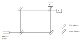
The Mach–Zehnder interferometer was developed by the physicists Ludwig Mach and Ludwig Zehnder. As shown in Figure 1, it uses two separate beam splitters (BS) to split and recombine the beams, and has two outputs, which can e.g. Be sent to photodetectors. The optical path lengths in the two arms may be nearly identical (as in the figure), or may be different (e.g. With an extra delay line). The distribution of optical powers at the two outputs depends on the precise difference in optical arm lengths and on the wavelength (or optical frequency).

The upper path picks up the following phase shifts on the way to detector A: π at the first reflection, π at the second (100%) reflection, nothing at the transmission, 2πl1/λ for the distance travelled, and 2πt/λ for the extra phase picked up in traversing the glass substrates where the wavelength is reduced. This gives a total of

The lower path, also on its way to A, picks up a phase shift of π off the 100% reflector, π at the second beam splitter, a phase shift of 2πl2/λ for the distance travelled, and an extra phase shift of 2πt/λ from passing through the glass substrate at the first beam splitter. The phase difference between the two paths is

Where δ is the phase shift due to the difference in the path lengths. Similarly, we can calculate the phase difference between the two paths on their way to detector B. We obtain

If the interferometer is well aligned, the path length difference can be adjusted (e.g. By slightly moving one of the mirrors)
Q 10 In a Newton’s ring experiment, the diameter of the 5th ring is 0.30 cm and diameter of the 15th ring is 0.62cm. Find the diameter of the 25th ring
Answer:
Diameter of Newton’s 5th ring = 0.30 cm
Diameter of Newton’s 15th ring = 0.62 cm
And Diameter of Newton’s 25th ring =?
From Newton’s rings experiment we know

Or D2n+m − D2n = 4λmR
For 5th and 15th rings
D215 − D25 = 4λ × 10 × R _______ (1) (m = 10)
For 15th and 25th rings
D225 − D215 = 4λ × 10 × R _______ (2) (m = 10)
Equation (2) = Equation (1)
D225 − D215 = D215 − D25
Or D225 = 2D215 – D25
Substituting the values,
D225 = 2 × 0.62 × 0.62 – 0.3 × 0.3 =0.6788 cm2
∴ D25 = 0.8239 cm
Question bank
Unit 2
Q 1 Newton’s rings are observed in the reflected light of wave length 5900 Å. The diameter of 10th dark ring is 0.5 cm. Find the radius of curvature of the lens used.
Answer:
The given data are
Wave length of light (λ) = 5900 Å= 5900 × 10–10 m
Diameter of 10th Newton’s dark ring (D10) = 0.5 cm = 0.5 × 10⁻² m
Radius of curvature of lens (R) =?
Formula is D2n = 4nλR

Q 2 Calculate the thickness of air film at the 10th dark ring in a Newton’s rings system, viewed normally by a reflected light of wave length 500 nm. The diameter of the 10th dark ring is 2 mm.
Answer:
Given data are
Wave length of light (λ) = 500 nm = 500 × 10–9 m
Number of the dark ring viewed (n) = 10
Diameter of 10th dark ring (D10) = 2 mm = 2 × 10⁻³ m
Radius of 10th dark ring 
Thickness of air film (t) =?
Condition for dark ring is
Q 3 What are condition of interference?
Answer:
Condition for Interference
To obtain the stable interference pattern the following conditions are required
Condition for Sustained Interference Pattern
a. The two interfering waves should be coherent i.e., both light waves are in same phase or maintain constant phase difference between them.
b. The source must be monochromatic
c. Both the wave must be in same set of polarization.
Condition for observation of fringes
a. The distance between the coherent sources be small
b. The distance between the source and screen must be large
Condition for Good Contrast
a. The amplitude of the both interfering waves be the same or very nearly same.
b. The sources must be narrow
c. The interfering angle should be very small or both travel in the same direction.
Q 4 Explain the Rayleigh criterion for limit of resolution?
Answer:
Rayleigh Criterion of Resolution
Statement: Two sources are resolvable by an optical instrument when the central maximum of one diffraction pattern falls over the first minimum of the other diffraction pattern and vice versa.
For example:
Let us consider the resolution of two wavelengths and by a grating. When the difference in wavelengths is smaller and such that the central maximum of the wavelength coincides with the first minimum of the other as shown in figure, then the resultant intensity curve is as shown by the thick curve. The curve shows a distinct dip in the middle of two central maxima. Thus, the two wavelengths can be distinguished from one another and according to Rayleigh they are said to be “Just Resolved”.
If the difference in wavelengths is such that their principal maxima are separately visible, then there is a distinct point of zero intensity in between the two wavelengths. Hence according to Rayleigh, they are said to be “Resolved”.
When the difference in wavelengths is so small that the central maxima corresponding to two wavelengths come still closer as shown in figure, then the resultant intensity curve is quite smooth without any dip. This curve is as if there is only one wavelength somewhat bigger and stronger.
Hence according to Rayleigh, the two wavelengths are “Not Resolved”.
Thus, the two spectral lines can be resolved only up to a certain limit expressed by Rayleigh Criterion.

Q 5 Explain Huygens principal of wave?
Answer:
Huygens' Principle
In 1678 Huygens proposed a model where each point on a wavefront may be regarded as a source of waves expanding from that point. The expanding waves may be demonstrated in a ripple tank by sending plane waves toward a barrier with a small opening. If waves approaching a beach strike a barrier with a small opening, the waves may be seen to expand from the opening.

Huygens' principle provides a convenient way to visualize refraction. If points on the wavefront at the boundary of a different medium serve as sources for the propagating light, one can see why the direction of the light propagation changes.
The Huygens' principle view permitted a visualization of how light could penetrate into the geometric shadow in a way that the particle view could not
Though helpful in establishing a wave view rather than a particle view of light for ordinary optics, Huygens' principle left a number of unanswered questions. For example, with its view of each point on a wavefront as a source, it gave no explanation of why it didn't propagate backward as well as forward.
Q 6 Give brief explanation of young double slit experiment?
Answer:
Young allowed the sunlight to pass a through a pin hole So on first screen followed by S1 and S2 at some distance on second screen as shown in figure. On the screen he observed few coloured bright and dark bands. To increase the brightness of bands the pin holes S1 and S2 are replaced by narrow slits and to increase the number of fringes sunlight is replaced by monochromatic source. Finally, the interference pattern consists of equally spaced bright and dark fringes are obtained.
Explanation of Experiment
Spherical wave came out as the sunlight passes through the pin hole So, (as per Huygens’s wave theory), the radii of these waves increases as they move away from So, when these spherical waves reaches the second screen again spherical waves came out from S1 and S2, these waves move away from S1 and S2 and hence they superimpose on each other. At the point where wave crest (or trough) of one wave fall on the wave crest (trough) of other, the resultant amplitude is maximum (maximum intensity, as I = A2) and where the wave crest of one fall on the wave trough of other, the resultant intensity is minimum. In this way large number of dark and bright bands are formed on screen.
Condition for Constructive and Destructive Interference
Consider that S1 and S2 are two coherent sources. If a1 and a2 are the amplitude of wave from S1 and S2 respectively. d is the phase difference between the two waves in reaching point P on the screen.
The displacement of the two waves can be given as
 .........................(2.1)
 ...........(2.2)
According to the theory of superposition, the resultant displacement


Or 
Say  ..................(2.3)
and  ................................(2.4)
Substituting these values


Squaring and adding eq 2.3 and 2.4, the resultant amplitude at P, will be

 ...................(2.5)
Therefore, the intensity at point P (I = R2)
 ..................(2.6)
Condition for Constructive Interference (Maxima)
Intensity at P will be maximum if 
i.e. 
Or Path Difference  ........................(2.7)


Q 7 Two coherent sources whose intensity ratio is 36:1 produce interference fringes. Deduce the ratio of maximum intensity to minimum intensity.
Answer:
Intensities ratio of coherent sources = a21 : a22 = 36: 1
∴ a1 : a2 = 6: 1
Minimum intensity of the interference fringe = (a1 – a2)2
= (6 – 1)2 = 25
Maximum intensity of the interference fringe = (a1 + a2)2
= (6 + 1)2 = 49
The ratio of maximum intensity to minimum intensity = 49 : 25 ≈ 2 : 1
Q 8 Define following?
1 Diffraction Grating
2 Resolving power
Answer:
It is defined as the capacity of a grating to form separate diffraction maxima of two wavelengths which are very close to each other
It is measured by  where
where  is the smallest difference in two wavelengths which are just resolvable by grating and
 is the wavelength of either of them or mean wavelength.
Let AB represent the surface of a plane transmission grating having grating element (e+d) and N total number of slits. Let a beam of light having two wavelengths  and
and  is normally incident on the grating. Let P1 is nth primary maximum of a spectral line of wavelength
  at an angle of diffraction
  and P2 is the nth primary maximum of wavelength
  at diffracting angle
According to Rayleigh criterion, the two wavelengths will be resolved if the principal maximum  of nth order in a direction
  falls over the first minimum of nth order in the same direction
  . Let us consider the first minimum of l of nth order in the direction
  as below.
The principal maximum of  in the
  direction is given by
 ...
...
The equation of minima is  where m takes all integers except 0, N, 2N, …, nN, because for these values of m, the condition for maxima is satisfied. Thus, first minimum adjacent to nth principal maximum in the direction
 can be obtained by substituting the value of ‘m’ as (nN+1). Therefore, the first minimum in the direction of
  is given by

 ..
..
The principal maximum of  in direction
  is given by
 ..
..
Dividing eqns, we get


 .
.
Thus, the resolving power is directly proportional to
(i) The order of the spectrum ‘n’
(ii) The total number of lines on the grating ‘N’
Q 9 What is Mach-Zehnder interferometer?
Answer:
The Mach–Zehnder interferometer was developed by the physicists Ludwig Mach and Ludwig Zehnder. As shown in Figure 1, it uses two separate beam splitters (BS) to split and recombine the beams, and has two outputs, which can e.g. Be sent to photodetectors. The optical path lengths in the two arms may be nearly identical (as in the figure), or may be different (e.g. With an extra delay line). The distribution of optical powers at the two outputs depends on the precise difference in optical arm lengths and on the wavelength (or optical frequency).
The upper path picks up the following phase shifts on the way to detector A: π at the first reflection, π at the second (100%) reflection, nothing at the transmission, 2πl1/λ for the distance travelled, and 2πt/λ for the extra phase picked up in traversing the glass substrates where the wavelength is reduced. This gives a total of

The lower path, also on its way to A, picks up a phase shift of π off the 100% reflector, π at the second beam splitter, a phase shift of 2πl2/λ for the distance travelled, and an extra phase shift of 2πt/λ from passing through the glass substrate at the first beam splitter. The phase difference between the two paths is

Where δ is the phase shift due to the difference in the path lengths. Similarly, we can calculate the phase difference between the two paths on their way to detector B. We obtain

If the interferometer is well aligned, the path length difference can be adjusted (e.g. By slightly moving one of the mirrors)
Q 10 In a Newton’s ring experiment, the diameter of the 5th ring is 0.30 cm and diameter of the 15th ring is 0.62cm. Find the diameter of the 25th ring
Answer:
Diameter of Newton’s 5th ring = 0.30 cm
Diameter of Newton’s 15th ring = 0.62 cm
And Diameter of Newton’s 25th ring =?
From Newton’s rings experiment we know

Or D2n+m − D2n = 4λmR
For 5th and 15th rings
D215 − D25 = 4λ × 10 × R _______ (1) (m = 10)
For 15th and 25th rings
D225 − D215 = 4λ × 10 × R _______ (2) (m = 10)
Equation (2) = Equation (1)
D225 − D215 = D215 − D25
Or D225 = 2D215 – D25
Substituting the values,
D225 = 2 × 0.62 × 0.62 – 0.3 × 0.3 =0.6788 cm2
∴ D25 = 0.8239 cm