Unit 2
1 and 3 Phase AC Circuit
- Explain the generation of sinusoidal voltage ?

Schematic diagram for single phase ac generation
A multi-turn coil is placed inside a magnet with an air gap as shown in Figure. The flux lines are from North Pole to South Pole. The coil is rotated at an angular speed, ω = 2π n (rad/s).
n = w/2π = speed of the coil (rev/sec or rps)
N = 60 . n = speed of the coil (rev/min or rpm)
l = length of the coil
b = width of the diameter
T = turns of the coil
B= flux density in the air gap (Wb/m2 )
v = π . b. n (tangential velocity of the coil)

(a) Coil position
(b) Details
At a certain instant t, the coil is an angle (rad), θ = ωt with the horizontal
The emf (V) induced on one side of the coil (conductor) is B l v sinθ , θ can also be termed as angular displacement.
The emf induced in the coil (single turn) is θ = 2B l π b n sinθ
The total emf induced or generated in the multi-turn coil is e(θ )= T2B l π b n sinθ = 2 π B l b n T sin  = Em sin
This emf as a function of time, can be expressed as, e(t) = Em sin wt . The graph of e(t) or e( ) which is a sinusoidal waveform s show in figure .

The area of the coil (m 2 ) = a = lb .
Flux cut by the coil (Wb) = ɸ = a . B = l . b . B
Flux linkage (wb) = 
It may be noted these values of flux φ and flux linkage ψ , are maximum, with the coil being at horizontal position, θ = 0 . These values change, as the coil moves from the horizontal position as shown in the figure (b).
The maximum value of the induced emf is
Em = 2 π n B l b T = 2π n ɸ T = 2π n Ѱ= w Ѱ = Ѱ . d
Determination of frequency (f) of the emf generated is
f = w/ (2π) = n , no of poles being 2 that is having only one pole pair.
In the ac generator no of poles = p and the speed (rps) = n, then the frequency in Hz or cycles/sec is
F= no of cycles / sec = no of cycles per rev x no of rev per sec = no of pairs of poles x bno of rev per sec = (p/2) n
Or f = pN/120 = p/2. w/2π
2.Define
- Average value,
- Root mean square,
- Form factor and
- Peak factor of sinusoidal voltage
Average Value:

The arithmetic mean of all the value over complete one cycle is called as average value

 =
= 
For the derivation we are considering only hall cycle.
Thus  varies from 0 to ᴫ
i = Im Sin


Solving
We get


Similarly, Vavg=
The average value of sinusoid ally varying alternating current is 0.636 times maximum value of alternating current.
RMS value: Root mean square value

The RMS value of AC current is equal to the steady state DC current that required to produce the same amount of heat produced by ac current provided that resistance and time for which these currents flows are identical.

I rms = 
Direction for RMS value:
Instantaneous current equation is given by
i = Im Sin 
But 
I rms = 
= 
=
=
Solving
=
=
Similar we can derive
V rms=  or 0.707 Vm
 the RMS value of sinusoidally alternating current is 0.707 times the maximum value of alternating current.
Form factor = RMS value / Average value = 0.707 Vmax/ 0.637 Vmax = 1.11
Peak Factor = Peak value / RMS value = 1.414
3.Explain current and phasor representation?
Consider the line OA (or phasor as it is called) representing to scale the maximum value of an alternating quantity that is emf OA = Emax and rotating in counter-clockwise direction at an angular velocity ω radians/second about the point O, as shown in Figure.
An arrow- head is put at outer end of the phasor to indicate which end is assumed to move and partly to indicate the precise length of phasor when two or more phasors happen to coincide.
The Figure shows OA rotated through an angle θ equal to ωt, from the position occupied when the emf was passing through its zero value.
The projection of OA on Y-axis, OB = OA sin θ = Emax sin ωt = e, the value of the emf at that instant.

Thus, the projection of OA on the vertical axis represents to scale the instantaneous value of emf.
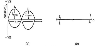
If I1 is taken as reference phasor, the two currents can be expressed as:
i1 = I1 max sin ωt
And i2 = I2 sin (ωt – ɸ)
The two quantities are said to be in phase with each other if they pass through zero values at the same instant and rise in the same direction, as shown in Figure.

But the two quantities passing through zero values at the same instant but rising in opposite directions, as shown in Figure are said to be in phase opposition that is phase difference is 180°.
When the two alternating quantities have a phase difference of 90° or π/2 radians they are said to be in quadrature.
4. Explain analysis of R,L,C circuits?
Ac circuit containing pure resisting

Consider Circuit Consisting pure resistance connected across ac voltage source
V = Vm Sin ωt ①
According to ohm’s law i =  =
= 
But Im = 
 ②
②
Phases diagram
From ① and ② phase or represents RMD value.
Power P = V. i
Equation P = Vm sin ω t Im sin ω t
P = Vm Im Sin2 ω t
P =  -
- 

Constant fluctuating power if we integrate it becomes zero

Average power
Pavg = 
Pavg = 
Pavg = Vrms Irms
Power ware form [Resultant]

Ac circuit containing pure Inductors

Consider pure Inductor (L) is connected across alternating voltage. Source
V = Vm Sin ωt
When an alternating current flow through inductance it set ups alternating magnetic flux around the inductor.
This changing the flux links the coil and self-induced emf is produced
According to faradays Law of E M I
e = 
At all instant applied voltage V is equal and opposite to self-induced emf [ lenz’s law]
V = -e
 =
= 
But V = Vm Sin ωt

 dt
dt
Taking integrating on both sides
 dt
dt
 dt
dt

 (-cos
(-cos  )
)


But sin (– ) = sin (+
 )
)
 sin (
sin ( -
-  /2)
/2)
And Im= 
 /2)
/2)
 /2
/2
= -ve
= lagging
= I lag v by 900
Waveform:
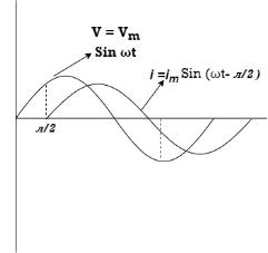
Phasor:

Power P = Ѵ. I
= Vm sin wt Im sin (wt  /2)
/2)
= Vm Im Sin wt Sin (wt –  /s)
/s)
 ①
①
And
Sin (wt -  /s) = - cos wt ②
Sin (wt –  ) = - cos
 sin 2 wt from ① and ②
The average value of sin curve over a complete cycle is always zero

 Pavg = 0
Ac circuit containing pure capacitors:
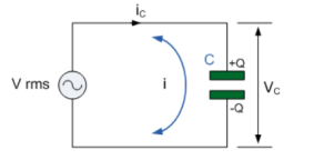
Consider pure capacitor C is connected across alternating voltage source
Ѵ = Ѵm Sin wt
Current is passing through capacitor the instantaneous charge ɡ produced on the plate of capacitor
ɡ = C Ѵ
ɡ = c Vm sin wt
The current is rate of flow of charge

i= (cvm sin wt)
i = c Vm w cos wt
Then rearranging the above eqth.
i =  cos wt

 = sin (wt +
  X/2)
X/2)
i =  sin (wt + X/2)
But 
 X/2)
X/2)

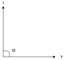
= leading
= I leads V by 900
Waveform :

Phase
Power P= Ѵ. i
= [Vm sinwt] [ Im sin (wt + X/2)]
= Vm Im Sin wt Sin (wt + X/2)]
 (cos wt)


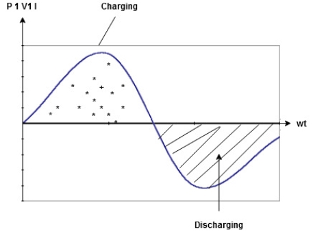
 to charging power waveform [resultant].
5. Explain R-L, R-C and R-L-C circuits?
Series R-L Circuit
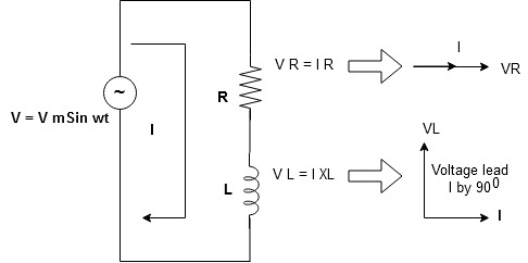
Consider a series R-L circuit connected across voltage source V= Vm sin wt
As some I is the current flowing through the resistor and inductor due do this current voltage drops arcos R and L R  VR = IR and L
  VL = I X L
 Total V = VR + VL
V = IR + I X L  V = I [R + X L]


Take current as the reference phasor : 1) for resistor current is in phase with voltage 2) for Inductor voltage leads current or current lags voltage by 90 0.
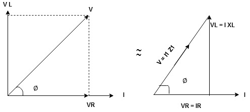
For voltage triangle
Ø is power factor angle between current and resultant voltage V and
V = 

V = 

Where Z = Impedance of circuit and its value is  =
= 
Impedance Triangle
Divide voltage triangle by I
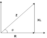
Rectangular form of Z = R+ixL
And polar from of Z =  L +
L + 
(+ j X L +  because it is in first quadrant )
Where  =
= 
 + Tan -1
Current Equation :
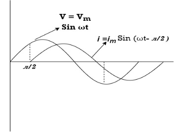
From the voltage triangle we can sec. That voltage is leading current by  or current is legging resultant voltage by
Or i =  =
=  [ current angles - Ø )

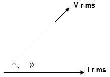
Resultant Phasor Diagram from Voltage and current eqth.
Wave form
Power equation
P = V .I.
P = Vm Sin wt Im Sin wt – Ø
P = Vm Im (Sin wt) Sin (wt – Ø)
P =  (Cos Ø) - Cos (2wt – Ø)
Since 2 sin A Sin B = Cos (A-B) – Cos (A+B)
P =  Cos Ø -
  Cos (2wt – Ø)

①②
Average Power
Pang =  Cos Ø
Cos Ø
Since ② term become zero because Integration of cosine come from 0 to 2ƛ
 pang = Vrms Irms cos Ø watts.
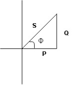
Power Triangle :
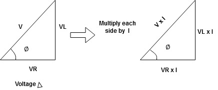
From 
VI = VRI + VLI B
Now cos Ø in  A =
A = 
 ①
①
Similarly Sin  =
= 


Apparent Power Average or true Reactive or useless power
Or real or active
-Unit (VI) Unit (Watts) C/W (VAR) denoted by (Ø)
Denoted by [S] denoted by [P]
Power  for R L ekt.
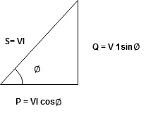
Series R-C circuit
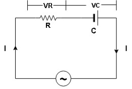
V = Vm sin wt
VR

 I
I
- Consider a series R – C circuit in which resistor R is connected in series with capacitor C across a ac voltage so use V = VM Sin wt (voltage equation).
- Assume Current I is flowing through
R and C  voltage drops across.
R and C  R
R  VR = IR
And C  Vc = I
 c
c


 V =
V =  lZl
lZl
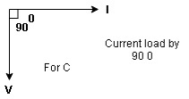
Voltage triangle : take current as the reference phasor 1) for resistor current is in phase with voltage 2) for capacitor current leads voltage or voltage lags behind current by 900
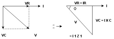
Where Ø is power factor angle between current and voltage (resultant) V
And from voltage
V = 
V = 
V = 
V =  lZl
lZl
Where Z = impedance of circuit and its value is lZl = 
Impendence triangle :
Divide voltage  by
by  as shown
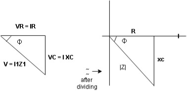
Rectangular from of Z = R - jXc
Polar from of Z = lZl L - Ø
( - Ø and –jXc because it is in fourth quadrant ) where
LZl = 
And Ø = tan -1 
Current equation :
From voltage triangle we can see that voltage is lagging current by Ø or current is leading voltage by Ø
 i = IM Sin (wt + Ø) since Ø is +ve
Or i =  for RC
 LØ [ resultant current angle is + Ø]
Resultant phasor diagram from voltage and current equation

Resultant wave form :

Power Equation :
P = V. I
P = Vm sin wt. Im Sin (wt + Ø)
= Vm Im sin wt sin (wt + Ø)
2 Sin A Sin B = Cos (A-B) – Cos (A+B)
 -
- 
Average power
Pang =  Cos Ø
Cos Ø
Since 2 terms integration of cosine wave from 0 to 2ƛ become zero
 2 terms become zero
 pang = Vrms Irms Cos Ø
Power triangle RC Circuit:
R-L-C series circuit
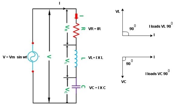
Consider ac voltage source V = Vm sin wt connected across combination of R L and C. When I flowing in the circuit voltage drops across each component as shown below.
VR = IR, VL = I  L, VC = I
  C
C
- According to the values of Inductive and Capacitive Reactance I e XL and XC decides the behaviour of R-L-C series circuit according to following conditions
① XL> XC, ② XC> XL, ③ XL = XC
① XL > XC: Since we have assumed XL> XC
 Voltage drop across XL> than XC
 VL> VC A
- Voltage triangle considering condition A

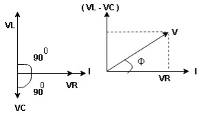
VL and VC are 180 0 out of phase .
Therefore cancel out each other
 Resultant voltage triangle
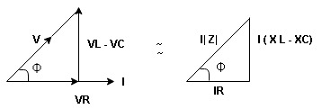
Now V = VR + VL + VC c phasor sum and VL and VC are directly in phase opposition and VL
 VC
VC their resultant is (VL - VC).
From voltage triangle
V = 
 V =
V = 
 V = I
V = I 

Impendence  : divide voltage
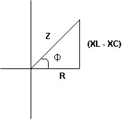
Rectangular form Z = R + j (XL – XC)
Polor form Z =  l + Ø B
Where  =
= 
And Ø = tan-1 
- Voltage equation : V = Vm Sin wt
- Current equation
i =  from B
i =  L-Ø C
L-Ø C
As VL VC the circuit is mostly inductive and
  I lags behind V by angle Ø
 Since i =
  L-Ø
L-Ø
 i = Im Sin (wt – Ø) from c
- XC
 XL :Since we have assured XC
  XL
XL
 the voltage drops across XC
  than XL
 XC
XC  XL (A)
 voltage triangle considering condition (A)
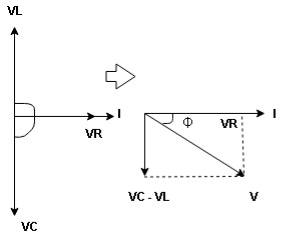
 Resultant Voltage
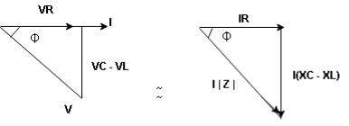
Now V = VR + VL + VC  phases sum and VL and VC are directly in phase opposition and VC
 VL
VL  their resultant is (VC – VL)
From voltage 
V = 
V = 
 V =
V = 
 V =
V = 

 Impedance
  : Divide voltage
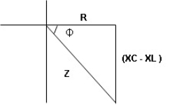
- Rectangular form : Z + R – j (XC – XL) – 4th qurd
Polar form : Z =  L -
L -
Where 
And Ø = tan-1 – 
- Voltage equation : V = Vm Sin wt
- Current equation : i =
 from B
 - i =
 L+Ø C
L+Ø C
As VC  the circuit is mostly capacitive and
  leads voltage by angle Ø
Since i =  L + Ø
L + Ø
 Sin (wt – Ø) from C
- Power
 :
:
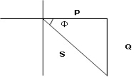
- XL= XC (resonance condition):
ɡȴ XL= XC then VL= VC and they are 1800 out of phase with each other  they will cancel out each other and their resultant will have zero value.
Hence resultant V = VR and it will be in phase with I as shown in below phasor diagram.
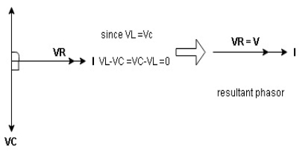
From above resultant phasor diagram
V =VR + IR
Or V = I  lZl
lZl
Because lZl + R
Thus Impedance Z is purely resistive for XL = XC and circuit current will be in phase with source voltage.

 Since VR=V Øis zero when XL = XC
  power is unity
Ie pang = Vrms I rms cos Ø = 1 cos o = 1
Maximum power will be transferred by condition. XL = XC
6. Define Apparent Power , Real power and Reactive power
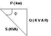
Apparent power (S) : it is defined as product of rms value of voltage (V) and current (I) or it is the total power / max power
S = V 
 Unit - volt – Ampere (VA)
In kilo – K. V. A.
- Real power / true power / active power / useful power : [P] it is defined as the product of rms value active component or it is the average power or actual power consumed by the resistive part (R) in the given combinational circuit
It is measured in watts
P = VI Cos Ø watts /km where Ø is the power factor angle
2. Reactive power / Imaginary / useless power [Q]
It is defined as the product of voltage current and sine of angle between V and


Volt Amp Relative
 Unit – V A R

 Power triangle
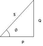
- As we know power factor is cosine of angle between voltage and current
i e P.F. = Cos 
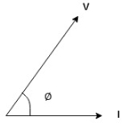
In other words also we can derive it from impedance triangle
Now consider Impedance triangle in R – L- ckt.
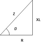
From  now Cos
  = power factor =
 power factor = Cos
  or
or 
7. Explain series, parallel and series-parallel circuits?
A series circuit is a circuit in which resistors are arranged in a chain, so the current has only one path to take. The current is the same through each resistor. The total resistance of the circuit is found by simply adding up the resistance values of the individual resistors:
The equivalent resistance of resistors in series : R = R1 + R2 + R3 + ...

A series circuit is shown in the diagram above. The current flows through each resistor in turn. If the values of the three resistors are:
R1 = 8Ω, R2 = 8Ω and R3 = 4Ω . The total resistance is 8+8+4 = 20 Ω
With a 10 V battery, by V = I R the total current in the circuit is:
I = V / R = 10 / 20 = 0.5 A. The current through each resistor would be 0.5 A.
Parallel circuits
A parallel circuit is a circuit in which the resistors are arranged with their heads connected, and their tails connected together. The current in a parallel circuit breaks up, with some flowing along each parallel branch and re-combining when the branches meet again. The voltage across each resistor in parallel is the same.
The total resistance of a set of resistors in parallel is found by adding up the reciprocals of the resistance values, and then taking the reciprocal of the total:
Equivalent resistance of resistors in parallel: 1 / R = 1 / R1 + 1 / R2 + 1 / R3 +...
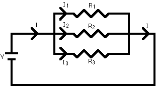
A parallel circuit is shown in the diagram above. In this case the current supplied by the battery splits up, and the amount going through each resistor depends on the resistance. If the values of the three resistors are:
R1 = 8 Ω, R2 = 8Ω and R3 = 4Ω. The total resistance is found by
1/R = 1/8 + 1/8 + ¼ = 1/2 . This gives R = 2 Ω.
With a 10 V battery, by V = I R the total current in the circuit is:
I = V / R = 10 / 2 = 5 A.
The individual currents can also be found using I = V / R. The voltage across each resistor is 10 V, so:
I1 = 10 / 8 = 1.25 A
I2 = 10 / 8 = 1.25 A
I3=10 / 4 = 2.5 A
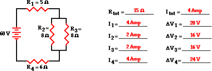
Series and parallel circuits:
The goal of the analysis is to determine the current in and the voltage drop across each resistor.
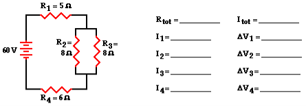
The first step is to simplify the circuit by replacing the two parallel resistors with a single resistor that has an equivalent resistance. Two 8 Ω resistors in series is equivalent to a single 4 Ω resistor. Thus, the two branch resistors (R2 and R3) can be replaced by a single resistor with a resistance of 4 Ω. This 4 Ω resistor is in series with R1 and R4. Thus, the total resistance is
Rtot = R1 + 4 Ω + R4 = 5 Ω + 4 Ω + 6 Ω
Rtot = 15 Ω
According to Ohms law
Itot = ΔVtot / Rtot = (60 V) / (15 Ω)
Itot = 4 Amp
Yet, resistors R1 and R4 are in series and the current in series-connected resistors is everywhere the same.
Thus,
Itot = I1 = I4 = 4 Amp
For parallel branches, the sum of the current in each individual branch is equal to the current outside the branches. Thus, I2 + I3 must equal 4 Amp. There are an infinite number of possible values of I2 and I3 that satisfy this equation.
Since the resistance values are equal, the current values in these two resistors are also equal. Therefore, the current in resistors 2 and 3 are both equal to 2 Amp.
I2 = I3 = 2 Amp
Now that the current at each individual resistor location is known, the Ohm's law equation (ΔV = I • R) can be used to determine the voltage drop across each resistor. These calculations are shown below.
ΔV1 = I1 • R1 = (4 Amp) • (5 Ω)
ΔV1 = 20 V
ΔV2 = I2 • R2 = (2 Amp) • (8 Ω)
ΔV2 = 16 V
ΔV3 = I3 • R3 = (2 Amp) • (8 Ω)
ΔV3 = 16 V
ΔV4 = I4 • R4 = (4 Amp) • (6 Ω)
ΔV4 = 24 V
8. Explain Resonance in series RLC circuits
Definition: it is defined as the phenomenon which takes place in the series or parallel R-L-C circuit which leads to unity power factor
Voltage and current in R – L - C ckt. Are in phase with each other
Resonance is used in many communicate circuit such as radio receiver.
Resonance in series RLC series resonance in parallel RLC anti resonance / parallel resonance.
- Condition for resonance XL = XC
- Resonant frequency (Fr) : for given values of R-L-C the inductive reactance XL become exactly aqual to the capacitive reactance Xc only at one particular frequency. This frequency is called as resonant frequency and denoted by (fr)
- Expression for resonant frequency(fr) : we know thet XL = 2ƛ FL - Inductive reactance
Xc =  - capacitive reactance
At a particular frequency ȴ = fr, the Inductive and capacitive reactance are exactly equal
 XL = XC ……at ȴ = fr
Ie  L =
L = 
 fr2 =
fr2 = 
 fr =
fr =  H2
H2
And  = wr =
  rad/sec
9. Explain parallel resonance ?
Parallel resonance:

A parallel resonant circuit stores the circuit energy in the magnetic field of the inductor and the electric field of the capacitor. This energy is constantly being transferred back and forth between the inductor and the capacitor which results in zero current and energy being drawn from the supply.
Admittance Y = 1/Z = √ G2 + B2
Conductance G = 1/R
Inductive susceptance BL = 1/ 2π f L
Capacitive susceptance Bc = 2π f C
10. Explain earthing?
Earthing is one of the main factors in electrical systems to protect the humans from getting electric shock. Earthing is used in almost every equipment.
Earthing is system in which the part of the equipment is connected to the earth with the help of the wires or cables. Earthing is also known as the grounding system.
Earthing is defined as the disharge of electric current in the earth with the help of the wires or cables having low resistance. Mostly Galvanised iron (G.I) strips are used for the earthing. Earthing protects the humans from getting electric shock from the leakage current and when a live wire or cable comes in the contact of the body of the equipment or from the short circuit current.
11. Explain the necessity and advantages of three phase circuits ?
Necessity :
Three phase systems are important for at-least three reasons :
First, nearly all electric power is generated and distributed at the operating frequency of 50Hz or 60 Hz . When one phase or two phase are required they are taken from the three phase system rather than generated independently.
Second, the instantaneous power in three phase system can be constant pulsating. This results in uniform power transmission and less vibration of three phase machines.
Third for the same amount of power the three- phase system is more economical than single phase. The amount of wire required for a three- phase system is less than that required for an equivalent phase system.
The output of 3 phase machine is always greater than single phase machine of same size.
Advantages:
- The output of 3 phase machine is always greater than single phase machine of same size.
- For transmission of electrical power three- phase supply requires less copper or less conducting material than that of single phase system for given volt-amperes and voltage ratings. Hence 3 phase system is more economical compared to single phase system
- Single phase machines are not self- starting machines. On the other hand three phase machines are self -starting due to rotating magnetic field. Therefore, to start a single- phase machine an auxiliary device is required which not in the case of 3 phase machine.
- Power factor of single- phase machines is poor compared to three phase machines.
12. Explain the generation of three phase power?
The three-phase power is mainly used for generation, transmission and distribution of electrical power because of their superiority. It is more economical as compared to single-phase power and requires three live conductors for power supply.
Power in a single-phase system or circuit is given by the relation shown below:
P= V I cos ɸ
Where,
V is the voltage of single-phase, i.e. Vph
I is the current of single-phase, i.e. Iph and
Cosϕ is the power factor of the circuit.
In 3 phase circuits (balanced load), the power is defined as the sum of various powers in a three-phase system given by
P = 3 Vph Iph cos ɸ
Power in star connections in a 3 phase circuits is given as
P= 3 VL/√3 IL cos ɸ----------------------(1)
The phase voltage and line voltage in the star connection is represented as shown below:
Vph = VL/ √3 and Iph = IL
Therefore, equation (1) can be written as:
P = √3 VL IL cos ɸ ……………………………………..(2)
Power in delta connections in 3 phase circuits is given by the equation shown below:
P = 3 VL . IL/√3 cos ɸ …………………………………(3)
In delta connections, the relation between phase and line voltage and phase and line current is given as:
Vph = VL and Iph = IL/ √3
Hence, equation (3) can be written as
P = 3 VL IL / √3 cos ɸ
Thus, the total power in a 3 phase balanced load system, irrespective of their connections, whether the system is star connected or delta connected, the power is given by the relation:
√3 VLILCosϕ
Its units are kilowatt (kW) or Watt (W).
13. What is balanced supply and balanced load?
The power supply system is said to be balanced if it fulfills the following criteria.
- The supply voltage is balanced in magnitude and phase angle.
- The impedance of the circuit is balanced
If the above two criteria are met the current in all three phases will be balanced and the system is said to be a balanced three-phase supply system.

Conditition1: SUPPLY Voltage is balanced

Condition 2: The impedance of the three phases is balanced.
Meeting the above two criteria, the current in all the three phases will be always balanced.
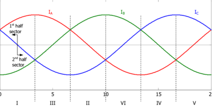
Balanced load in 3 phase system is a condition where all three phases (lines) carry same magnitude of current, with evenly spaced phase difference. If the load is star connected, with neutral as return path, this neutral will carry no current. This is so since vector sum of all three phase currents meeting at common neutral point is zero.
14. Relationship between line and phase values of balanced star and delta connections.
Star connection:
The terminal corresponding to first subscript is assumed to be at a higher potential with respect to the terminal corresponding to second subscript.

The voltage across each coil that is the voltage between A & A’,B& B’, and C & C’ are called phase voltages.
VAA, VBB, VCC, or VAN, VBN, VCN represent phase voltages. The voltages across line terminals A & B, B & C, C & D are called line voltages.
The connection diagram and the corresponding phasor diagram of voltages is shown in figure.
From the star connected 3 phase system the current flow through the lines A, B, C also flow through the respective phase windings.
Hence in star connected system, the phase currents and line currents are identical.
Phase current (Iph) = Line currents (IL) Iph= ILine
The voltage VAB between lines A and B is obtained by adding VAN and VNB respectively.
VAB = VAN+VNB = VAN - VBN
Similarly VBC = VBN+VNC = VBN – VCN
VCA = VCN+VNA = VCN – VAN
The line voltage VAB is obtained by adding VAN with reversed vector of VBN.
VAB bisects the angle between VAN and -VBN
VAB 2 = VL 2 = Vph 2 + Vph 2 + 2 VphVph cos 600
= 3Vph 2
VAB = √3 Vph
Line voltage = √3 phase voltage
The line voltages VAB, VBC, VCA are equal in magnitude and differ in phase by 1200
Hence, they form a balanced 3-phase voltage of magnitude √3 Vph.
The two voltages differ in phase by 300.
When the system is balanced, the three phase currents IA, IB, IC are balanced. The magnitude and phase angle of current is determined by circuit parameters. IA, IB, IC are line or phase currents.
The current in the neutral wire is IN and is by applying Kirchhoff’s current law at star point,
We get IN = -( IA+ IB+ IC) .
If the currents are balanced, then the neutral current is zero.
Delta connection

The currents flowing through the phase windings IAA’, IBB’, and ICC’ or IAB, IBC, and ICA are called phase currents and are balanced as shown in phase diagram Figure.
By applying KCL at node A
IA+ICA = IAB ,
IA = IAB - ICA
Similarly by applying KCL at nodes B and C
IB = IBC - IABIC
= ICA - IBC
The line current IA is obtained by adding IAB and –ICA vectorially.
IA bisects the angle between IAB and -ICA
IA 2 = ILine 2 = Iph 2 + Iph 2 + 2 IphIph cos 600
= 3Iph 2 IL = √3 Iph
Line current(IL) = √3 phase voltage(Iph)
The line current IA, IB, IC and also equal and differ in phase by 1200 . They form a balanced system of currents. The line and phase currents differ in phase by 300
15. Explain Power in balanced three phase circuits
In a balanced three phase system the magnitude of each line to neutral voltage is same as is the magnitude of each phase current. Therefore the expression for total power in term of phase current and phase voltage is given by
P = 3 V I cos  watt
watt
In terms of line voltage and line current the equation becomes
P = √3 VL IL cos  watt
watt
In the above expression V and I are the rms values of phase voltage and phase current . We can also calculate reactive power (Q) and complex power(S) . For balanced the expressions for Q and S are given by
Q = √3 VL IL sin  Var
Var
S= 3 VL IL VA
16.Explain Measurement of Power by two wattmeter method.
In two wattmeter method, a three- phase balanced voltage is to a balanced three phase load where the current in each phase is assumed lagging by an angle of Ø behind the corresponding phase voltage.
The schematic diagram for the measurement of three phase power using two wattmeter method is shown below.

From the figure the current through the Current Coil (CC) of Wattmeter W1 = IR , current though Current Coil of wattmeter W2 = IB whereas the potential difference seen by the Pressure Coil (PC) of wattmeter W1= VRB (Line Voltage) and potential difference seen by Pressure Coil of wattmeter W2 = VBY.
The phasor diagram of the above circuit is drawn by taking VR as reference phasor as shown below.

From the above phasor diagram,
Angle between the current IRand voltage VRB = (30° – Ø)
Angle between current IYand voltage VYB = (30° + Ø)
Therefore, Active power measured by wattmeter W1 = VRBIR Cos (30° – Ø)
Similarly, Active power measured by wattmeter W2 = VYBIYCos(30° + Ø)
As the load is balanced, therefore magnitude of line voltage will be same irrespective of phase taken i.e. VRY, VYB and VRB all will have same magnitude. Also for Star / Y connection line current and phase current are equal, say IR = IY = IB = I
Let VRY = VYB = VRB = VL
Therefore,
W1 = VRBIRCos (30° – Ø)
= VLICos(30° – Ø)
In the same manner,
W2 = VLICos(30° + Ø)
Hence, total power measured by wattmeters for the balanced three phase load is given as,
W = W1 + W2
= VLI×Cos(30° – Ø) + VLI×Cos(30° + Ø)
= VLI [Cos(30° – Ø) + Cos(30° + Ø)]
= 2VLI×Cos30°CosØ ……………….[ CosC + CosD = 2Cos(C+D)/2×Cos(C-D)/2 ]
=√3VLICosØ
Therefore, total power measured by wattmeters W = √3VLICosØ
Now, suppose you are asked to find the power factor of the load when individual power measured by the wattmeters are given, then we should proceed as
W1 + W2 = √3VLICosØ ……………………………..(1)
Similarly,
W1 – W2= VLI×Cos(30° – Ø) + VLI×Cos(30° + Ø)
= VLI [Cos(30° – Ø) + Cos(30° + Ø)]
= 2VLI×Sin30°SinØ ………[ CosC – CosD = 2Sin(C+D)/2×Sin(D-C)/2 ]
= VLISinØ
Hence,
W1 – W2 = VLISinØ ………………………………(2)
Dividing equation (2) by equation (1),
(W1 – W2) / (W1 + W2) = VLISinØ / √3VLICosØ
(W1 – W2) / (W1 + W2) = (tanØ) /√3
Hence,
Tanɸ = √3 [ (W1 – W2) / (W1 + W2)]
From the above equation, we can find the value of Ø and hence the power factor Cos Ø of the load.
Case1: When the power factor of load is unity.
As the power factor of load is unity, hence Ø = 0
Therefore,
Power measured by first wattmeter W1= VLI Cos(30° – 0)
= VLI Cos30°
= 0.866 VLI
Power measured by second wattmeter W2= VLI Cos(30° + 0)
= VLI Cos30°
= 0.866 VLI
Thus we see that, when the power factor of load is unity then both the wattmeter reads the same value.
Case2: When power factor of load is 0.5 lagging.
As power factor is 0.5 hence CosØ = 0.5 i.e. Ø = 60°
Therefore,
Power measured by first wattmeter W1= VLI Cos(30° – 60°)
= VLI Cos30° ……[Cos (-Ɵ) = CosƟ ]
= 0.866 VLI
Power measured by second wattmeter W2= VLI Cos(30° + 60°)
= VLI Cos90°
= 0
Thus, we see that, when power factor of load is 0.5 lagging then power is only measured by first wattmeter and reading of second wattmeter is ZERO.
Case3: When power factor of load is zero.
As power factor of load is zero, hence CosØ = 0 i.e. Ø = 90°
Therefore,
Power measured by first wattmeter W1= VLI Cos(30° – 90°)
= VLI Cos60°
= 0.5 VLI
Power measured by second wattmeter W2= VLI Cos(30° + 90°)
= –VLI Cos60°
= -0.5 VLI
It shall be noted that when 60° <Ø < 90°, reading of one wattmeter will be positive while the reading of second wattmeter will be negative.