Unit – 2
- Write a short note on Orthographic Projections?
If straight lines are drawn from various points on the contour of an object to meet a plane, the object is said to be projected on that plane. The figure formed by joining, in correct sequence, the points at which these lines meet the plane, is called the projection of the object. The lines from the object to the plane are called projectors.
Methods of Projection:
Following four methods of projection are commonly used,
1) Orthographic projection.
2) Isometric projection.
3) Oblique projection.
4) Perspective projection.
In the above methods 2, 3 and 4 represent the object by a pictorial view as eyes see it. In these methods of projection, a three-dimensional object is represented on a projection plane by one view only, while in the orthographic projection an object is represented by two or three views on the mutual perpendicular projection planes. Each projection view represents two dimensions of an object. For the complete description of the three-dimensional object at least two or three views are required.
Orthographic Projection:
Theory of orthographic projection:
Let us suppose that a transparent plane has been set up between an object and the station point of an observer's eye (Fig. 1). The intersection of this plane with the rays formed by lines of sight from the eye to all points of the object would give a picture that is practically the same as the image formed in the eye of the observer. This is perspective projection.

Figure 1 Perspective projection. The rays of the projection converge at the station point from which the object is observed.
If the observer would then walk backward from the station point until he reached a theoretically infinite distance, the rays formed by lines of sight from his eye to the object would grow longer and finally become infinite in length, parallel to each other, and perpendicular to the picture plane. The image so formed on the picture plane is what is known as "orthographic projection." See Fig.
2.
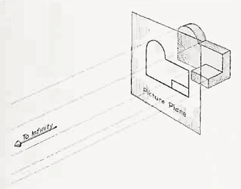
Figure 2 Orthographic projection.
Orthographic projections could be defined as any single projection made by dropping perpendiculars to a plane. However, it has been accepted through long usage to mean the combination of two or more such views, hence the following definition has been put forward: Orthographic projection is the method of representing the exact shape of an object by dropping perpendiculars from two or more sides of the object to planes, generally at right angles to each other; collectively, the views on these planes describe the object completely. (The term "orthogonal" is sometimes used for this system of drawing.)
2. What do you means by Orthographic views?
The rays from the picture plane to infinity may be discarded and the picture, or "view," thought of as being found by extending perpendiculars to the plane from all points of the object, as in Fig. 3. This picture, or projection on a frontal plane, shows the shape of the object when viewed from the front, but it does not tell the shape or distance from front to rear. Accordingly, more than one projection are required to describe the object.
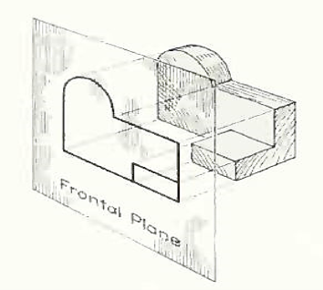
Figure 3 The frontal plane of projection. This produces the front view of the object.
In addition to the frontal plane, imagine another transparent plane placed horizontally above the object, as in Fig. 4. The projection on this plane, found by extending perpendiculars to it from the object, will give the appearance of the object as if viewed from directly above and will show the distance from front to rear.
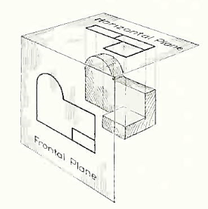
Figure 4 The frontal and horizontal planes of projections. Projection on the horizontal plane produces the top view of the object.
If this horizontal plane is now rotated into coincidence with the frontal plane, as in Fig. 5, the two views of the object will be in the same plane, as if on a sheet of paper.

Figure 5 The horizontal plane rotated into the same plane as the frontal plane.
Now imagine a third plane, perpendicular to the first two (Fig. 6). This plane is called a "profile plane," and a third view can be projected on it. This view shows the shape of the object when viewed from the side and the distance from bottom to top and front to rear.
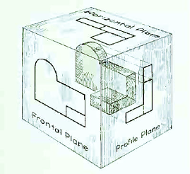
Figure 6 The three planes of projection: frontal, horizontal and profile. Each is perpendicular to other two.
The horizontal and profile planes are shown rotated into the same plane as the frontal plane (again thought of as the plane of the drawing paper) in Fig. 7. Thus, related in the same plane, they give correctly the three-dimensional shape of the object.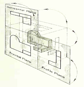
Figure 7 The horizontal and profile planes rotated into the same plane as the frontal plane. This makes it possible to draw three views of the object.
In orthographic projection the picture planes are called "planes of projection"; and the perpendiculars, "projecting lines" or "projectors.
3. Explain Projections of Points and lines inclined to both planes?
A point may be situated, in space, in any one of the four quadrants formed by the two principal planes of projection or may lie in any one or both. Its projections are obtained by extending projectors perpendicular to the planes.
One of the planes is then rotated so that the first and third quadrants are opened out. The projections are shown on a flat surface in their respective positions either above or below or in xy.
If a point is situated in the first quadrant,
The pictorial view [fig. 14 (i)] shows a point A situated above the H.P. And in front of the V.P., i.e. in the first quadrant. a' is its front view and the top view. After rotation of the plane, these projections will be shown in fig. 14 (ii).
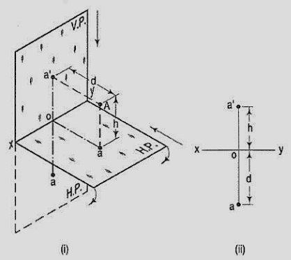
Figure 14
The front view a' is above xy and the top view a below it. The line joining a' and a (which also is called a projector), intersects xy at right angles at a point o. It is quite evident from the pictorial view that a'o = Aa, i.e. the distance of the front view from xy = the distance of A from the H.P. Viz. h. Similarly, ao = Aa',i.e. the distance of the top view from xy = the distance of A from the V.P. Viz. d.
If a point is situated in second quadrant,
A point B (fig. 15) is above the H.P. And behind the V.P., i.e. in the second quadrant. b' is the front view and b the top view. When the planes are rotated, both the views are seen above xy. Note that b'o = Bb and bo = Bb'.

Figure 15
If a point is situated in third quadrant,
A point C (fig. 16) is below the H.P. And behind the Y.P., i.e. in the third quadrant. Its front view c' is below xy and the top view c above xy. Also, c'o = Cc and co = Cc'.
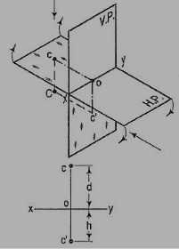
Figure 16
If a point is situated in 4th quadrant,
A point f (fig. 17) is below the H.P. And in front of the V.P., i.e. in the fourth quadrant. Both its projections are below xy, and e'o = Ee and eo = Ee'.
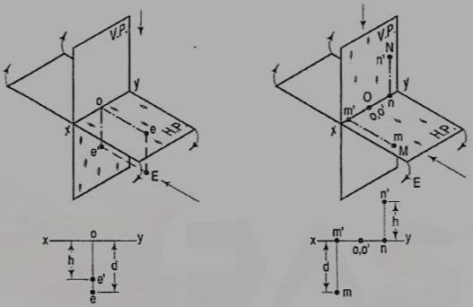
Figure 17
General conclusions:
1. The fine joining the top view and the front view of a point is always perpendicular to xy. It is called a projector.
2. When a point is above the H.P., its front view is above xy; when it is below the H.P., the front view is below xy. The distance of a point from the H.P. Is shown by the length of the projector from its front view to xy.
3. When a point is in front of the V.P., its top view is below xy; when it is behind the V.P., the top view is above xy. The distance of a point from the V.P. Is shown by the length of the projector from its top view to xy.
4. When a point is in a reference plane, its projection on the other reference plane is in xy.
4. A point P is in the first quadrant. Its shortest distance from the intersection point of H.P., V.P. And Auxiliary vertical plane, perpendicular to the H.P. And V.P. Is 70 mm and it is equidistant from principal planes (H.P. And V.P.). Draw the projections of the point and determine its distance from the H.P. And V.P.

Figure 18
Note: ‘O’ represents intersection of H.P., V.P. And A.V.P.
Drawing steps:
1. Draw xy and x1 y1 perpendicular reference lines.
2. ‘O’ represents intersection of H.P., V.P. And A.V.P.
3. Draw from O a line inclined at 45° of 70 mm length.
4. Project from P" on xy line and x1 y1. The projections are n and m respectively as shown in figure. From O draw arc intersecting x1 y1.
5. Draw a parallel line at convenient distance from x1 y1. Extend P"m to intersect
a parallel line at p' and p as shown.
6. Measure distance from xy line, which is nearly 49.4974 mm say 49.5 mm.
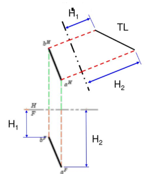
A straight line is the shortest distance between two points. Hence, the projections of a straight line may be drawn by joining the respective projections of its ends which are points.
5. The position of a straight line may also be described with respect to the two reference planes. What are they?
1. Parallel to one or both the planes.
2. Contained by one or both the planes.
3. Perpendicular to one of the planes.
4. Inclined to one plane and parallel to the other.
5. Inclined to both the planes.
6. Projections of lines inclined to both the planes.
7. Line contained by a plane perpendicular to both the reference planes.
8. True length of a straight line and its inclinations with the reference planes.
9. Traces of a line.
10. Methods of determining traces of a line.
11. Traces of a line, the projections of which are perpendicular to xy.
12. Positions of traces of a line.
Line parallel to one or both the planes:

Figure 19
(a) Line AB is parallel to the H.P.
a and b are the top views of the ends A and B respectively. It can be clearly seen that the figure ABba is a rectangle. Hence, the top view ab is equal to AB.
a'b' is the front view of AB and is parallel to xy.
(b) Line CD is parallel to the V.P. The line c'd' is the front view and is equal to CD; the top view cd is parallel to xy.
(c) Line ff is parallel to the H.P. And the V.P. Ef is the top view and e'f' is the front view; both are equal to ff and parallel to xy.
Hence, when a line is parallel to a plane, its projection on that plane is equal to its true length; while its projection on the other plane is parallel to the reference line.
6. Explain the process for the Projections of planes inclined Planes?
Plane figures or surfaces have only two dimensions, viz. Length and breadth. They do not have thickness. A plane figure may be assumed to be contained by a plane, and its projections can be drawn, if the position of that plane with respect to the principal planes of projection is known.
7. Explain various Type of planes.
Planes may be divided into two main types:
(1) Perpendicular planes.
(2) Oblique planes.
Perpendicular planes:
These planes can be divided into the following sub-types:
(i) Perpendicular to both the reference planes.
(ii) Perpendicular to one plane and parallel to the other.
(iii) Perpendicular to one plane and inclined to the other.
Perpendicular to both the reference planes (fig 1):
A square ABCD is perpendicular to both the planes. Its H.T. And V.T. Are in a straight-line perpendicular to xy.
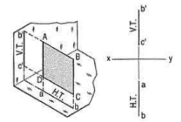
Figure 33
The front view b'c' and the top view ab of the square are both lines coinciding with the V.T. And the H.T. Respectively.
Perpendicular to one plane and parallel to the other plane:
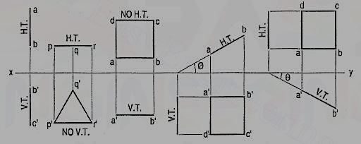
a) Plane, perpendicular to the H.P. And parallel to the V.P. [fig. 12-2(i)]. A triangle PQR is perpendicular to the H.P. And is parallel to the V.P. Its H.T. Is parallel to xy. It has no V.T.
The front view p'q'r' shows the exact shape and size of the triangle. The top view pqr is a line parallel to xy. It coincides with the H.T.
(b) Plane, perpendicular to the V.P. And parallel to the H.P. [fig. 12-2(ii)]. A square ABCD is perpendicular to the V.P. And parallel to the H.P. Its V.T. Is parallel to xy. It has no H.T.
The top view abed shows the true shape and true size of the square. The front view a'b' is a line, parallel to xy. It coincides with the V.T.

Figure 34
Perpendicular to one plane and inclined to the other plane:
A square ABCD is perpendicular to the H.P. And inclined at an angle φ to the V.P. Its V.T. Is perpendicular to xy. Its H.T. Is inclined at φ to xy.
Its top view ab is a line inclined at φ to xy. The front view a'b'c'd' is smaller than ABCD.

Figure 35
(b) Plane, perpendicular to the V.P. And inclined to the H.P. (fig. 12-4).
A square ABCD is perpendicular to the V.P. And inclined at an angle θ to the H.P. Its H.T. Is perpendicular to xy. Its V.T. Makes the angle e with xy. Its front view a'b' is a line inclined at θ to xy. The top view abed is a rectangle which is smaller than the square ABCD.

Figure 36
Fig. 36 shows the projections and the traces of all these perpendicular planes by third-angle projection method.
8. Give a brief description on Auxiliary Planes?
While drawing orthographic projection, such lines of the object which are parallel to principal or vertical plane are represented better.
Those lines which are inclined to the principal plane do not show the actual length.
If an edge or a face is to be shown in true size, it should be parallel to the plane of projection. ... These additional planes of projection which are set up to obtain the true sizes are called Auxiliary Planes. ▪ The views projected on these auxiliary planes are called Auxiliary Views. Auxiliary Views.
