Unit - 1
Important Vector Quantities
Q1) Explain Moment of a Force about a Specified Axis.
A1)
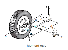
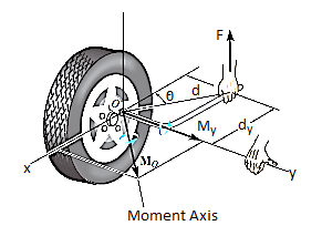
Sometimes, the moment produced by a force about a specified axis must be determined. For example, suppose the lug nut at O on the car tire in Fig. Above needs to be loosened. The force applied to the wrench will create a tendency for the wrench and the nut to rotate about the moment axis passing through O; however, the nut can only rotate about the y axis. Therefore, to determine the turning effect, only the y component of the moment is needed, and the total moment produced is not important. To determine this component, we can use either a scalar or vector analysis.
Scalar Analysis. To use a scalar analysis in the case of the lug nut in Fig. Above, the moment arm perpendicular distance from the axis to the line of action of the force is dy = d cos  . Thus, the moment will be
MOy = F (d cos )
)
Vector Analysis: To find the moment of force F in above figure about the y axis using a vector analysis, we must first determine the moment of the force about any point O on the y axis by applying MO = r x F. The component My along the y axis is the projection of MO onto the y axis. It can be found using the dot product discussed above, so that My = j*MO = j*(r x F) where j is the unit vector for the y axis.
We can generalize this approach by letting ua be the unit vector that specifies the direction of the axis shown in Fig. 4–21. Then the moment of F about the axis is

This combination is referred to as the scalar triple product. If the vectors are written in Cartesian form, we have


Equivalent Moment:
The equivalent moment acting on a system of forces can be calculated as illustrated in the following examples:
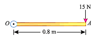
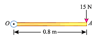
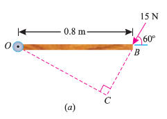
Q2) A force of 15 N is applied perpendicular to the edge of a door 0.8 m wide as shown in Fig. Below. Find the moment of the force about the hinge.
A2)
Given: Force applied (P) = 15 N and width of the door (l) = 0.8 m
Moment when the force acts perpendicular to the door as shown in fig.
We know that the moment of the force about the hinge is given as,
MO = P × l = 15 × 0.8 = 12.0 N-m
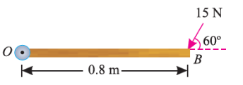
If the force is to be applied at a particular angle according to fig. Below,
Then the calculations are done in following procedure.
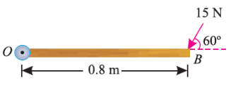
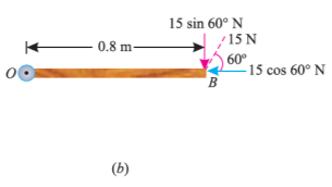
As the force applied in the question above is inclined at an angle of 600 with the horizontal, we can calculate the moment of force by two methods, either by finding out the perpendicular distance between the hinge and the line of action of the force as shown in Fig. (a) or by finding out the vertical component of the force as shown in Fig. (b) below.
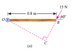

From the geometry of Fig. (a), we find that the perpendicular distance between the line of action of the force and hinge,
OC = OB sin 60° = 0.8 × 0.866 = 0.693 m
∴ Moment = 15 × 0.693 = 10.4 N-m
In the second case, we know that the vertical component of the force
= 15 sin 60° = 15 × 0.866 = 13.0 N
∴ Moment = 13 × 0.8 = 10.4 N-m
Q3) Write the properties of Couple.
A3)
1. Two unlike parallel, non-collinear forces of same magnitude will form couple.
2. Resultant of couple is always zero.
3. Moment of couple is product of one of the forces & lever arm of couple.
M = F xd
Lever arm of couple = ḻlar distance between couple forces.
4. Couple cannot be balanced by single force.
5. Couple can be balanced only by another couple of opposite nature.
6>. Moment of couple is independent of moment centre. i.e. Ref. Point is not required to take moment of couple.
Q4) A force of 15 N is applied at an angle of 600 to the edge of door as shown in figure. Find the moment of this force.

A4)
Resolving force at point B & then taking the moment about point O,
M0 = (15 Cos 60 x 0) + (15 Sin 60 x 0.8)
= 0 + 10.39
M0 = 10.39 N.m
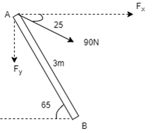
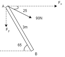
Q5) A 90 N force is applied to the control rod AB. Determine moment of this Force about point B.
A5)
As we don’t know perpendicular distance betn force & point ‘ B ’, Let us resolve the force into two components.
X – Component of force
Fx = 90 Cos 25 = 81.567 N
Y – Component of force
Fy = 90 Sin 25 = 38.036
Now taking moments about point B.
MB = [Fx x (3 Sin 65)] - [Fy x (3 Cos 65)]
MB = (81.65 x 2.72) – (38.036 x 1.27)
= 221.843 – 48.31
MB = 173.53 N.m
Q6) Determine the resultant of the system of forces acting on a beam as shown in figure.

A6)
Above Force system is Non concurrent force system.
Resolving the forces horizontally,
∑ Fx = - 20 Cos 60 = - 10 KN = 10 KN (toward left)
Resolving forces vertically,
∑Fy = - 20 – 30 – 20 Sin 60
= - 67.32 KN
∑Fy = 67.32 KN (downwards)
Resultant, R = √ (∑ Fx) 2 + (∑Fy) 2 = √10 2 + 67.322
R = 68.06 KN
Direction of Resultant,
Tanα = ∑Fy / ∑ Fx = 67.32 / 10.00
α = 81.550
Now taking moment about point A & using Varignon’s theorem.
∑MA = Moment of resultant A
(20 x 1.5) + (30 x 3) + (20 Sin 60 x 6) = (∑ Fx x 0 ) + (∑Fyx X)
223.92 = 67.32 x X
X = 223.92 / 67.32 = 3.326 m from point A
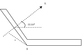
Q7) For a given force system, find the resultant in magnitude & direction. Also find the location of Resultant.

A7)

Resolving forces horizontally,
∑ Fx = - 15 + 25 Cos 40 = 4.15 N (toward right)
Resolving forces vertically,
∑Fy = 25 Sin 40 – 10
= 6.07 n (upward)
R = √(∑ Fx) 2 + (∑Fy)2
= √4.152 + 6.072
R = 7.35 N
Tanα = ∑Fy / ∑ Fx = 6.07 / 4.15
α= 55.640 - - - Angle made by resultant
To find exact position of R, let x is the perpendicular distance betn R & point B.
Using Varignon’s theorem at point B.
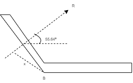
R x X = ∑MB
= (10 x 150) – (15 x 150 Sin 50) + ( 25 x 375 ) – ( 6.25 x 1000 )
= 1500 – 1723.6 + 9375 – 6250
= 2901.4 N.mm (clockwise)
x = 2901.4 / R
= 2901.4 / 7.35
x = 394.75 mm from point B.
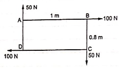
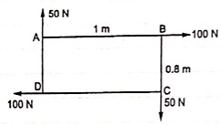
Q8) Find resultant moment of two couples for the loading as shown in Fig
A8)
Moment of 50 N couple is clockwise,
= 50 x 1
= 50 N.m
Moment of 100 N couple is also clockwise
= 100 x 0.8 = 80 N.m.
Resultant Moment = 50 + 80 = 130 N.m
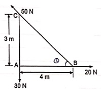
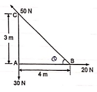
Q9) Find the resultant and its point of application on y – axis for the force system acting on Triangular plate as shown in fig.
A9)
θ = tan-1 (3/4)
= 36.860 with Horizontal
Resolving forces in x & y dirn
∑ Fx = 20 – 50 Cosθ
= 20 – 50 Cos 36.86
= - 20 N
= 20 N
∑Fy = - 30 + 50 Sin 36.86
= 0.00007
≈ 0
R = √(∑ Fx) 2 + (∑Fy)2
= 20 N toward left (as ∑ Fy = 0 )
Let us apply Varignons theorem at point B
∑MB = R.x
( 30 x 4 ) = Rx
Rx = -120 N.m = 120 N.m
As moment of Resultant is negative i.e. it is anticlockwise
-Rx = -120
X = -120 / -20 = 6 m
X = 6 m from point B and it will be above point. B to create anticlockwise moment.
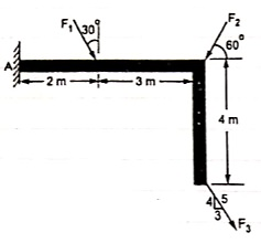
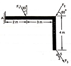
Q10) If the resultant moment about point A is 4800 Nm clockwise, determine the magnitude of F3 if F1 = 300 N and F2 = 400 N.
A10)
Given: Resultant Moment = 4800 N.m
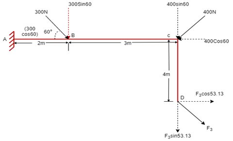
Let us apply Varignon’s theorem at point A,
∑MB = (R.x )
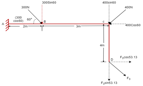
[(300 60) x 2] + [(400 Sin 60) x 5] + [(F3 Sin 53.13 x 5)] – [(F3 Cos 53.13) x 4] = 4800
519.62 + 1732.05 + 3.99 F3 – 2.4 F3 = 4800
2251.67 + 1.59F3 = 4800
F3 = 2548.33 / 1.59 F3 = 2548.33 / 1.6
OR
F3 = 1602.72 NF3 = 1592.7 N
Q11) The three forces shown in Fig. Create a vertical resultant acting through point B. If P = 361 N, compare the values of T and F.

A11)
From given figure,
1. Angle made by Force P is, = tan-1 (3/3) = 450 with Horizontal
2. Angle made by Force F is, = tan-1 (1/3) = 18.430 with Horizontal
3. Angle made by Force T is, = tan-1 (3/1) = 71.560 with Horizontal

Resolving forces along x & y dirn,
As Resultant is vertical, let it is upward, then
∑ Fx = 0& ∑Fy = R
∑ Fx = P Cos 45 + F Cos 18.43 – T Cos 71.56
0 = 361 Cos 45 + F Cos 18.43 – T Cos 71.56
0 = 255.26 + 0.95 F – 0.32 T
0.95 F – 0.32 T = - 255.26 . . . . (1)
∑Fy = P Sin 45 – F Sin 18.43 + T Sin 71.56
R = 361 Sin 45 – F Sin 18.43 + T Sin 71.56
R = 255.26 – 0.32 F + 0.95 T …… (2)
Now as it is given that Resultant acts at point B, let us apply Varignon’s theorem at point B.
∑MB = R.x
But as R is acting at B point, its perpendicular distance from point B itself will be zero.
∑MB = R.x
(P Cos 45 x 1) – (P Sin 45 x 2) + (T Cos 71.56 x 1) – (T Sin 71.56 x 1) – (F Cos 18.43 x 1) + (F Sin 18.43 x 2) = R x 0
As P = 361 N
-255.26 – (255.26 x 2) + 0.32 T – 0.95 T – 0.95 F + (0.32 F x 2) = 0
-765.78 + 0.32 T – 0.95 T – 0.95 F + 0.64 F = 0
-765.78 – 0.63 T – 0.31 F = 0
– 0.31 F – 0.63 T = 765.78 . . . . (3)
Solving equation (1) and (3) simultaneously

F = -581.716 N &
T = -929.282 N
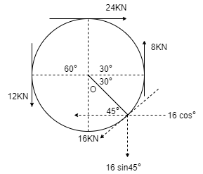
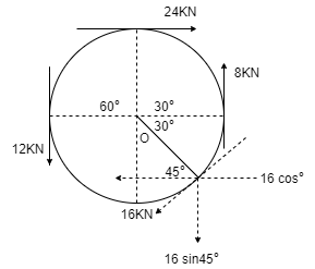
Q12) Determine the resultant of four forces tangent to the circle of radius 1.5 m as shown. Determine its location w.r.t. ‘O’.
A12)
Resolving forces in X and Y direction,
∑ Fx = 24 - 16 Cos 45
= 12.69 KN ( )
∑Fy = -12 + 8 – 16 Sin 45
= -15.31 kN
= 15.31 kN ( )
Resultant R = √(∑ Fx) 2 + (∑Fy)2
= √ 12.69 2 + (-15.31)2
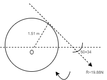
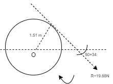
R = 19.88 kN
Direction of Resultant,
α = tan-1(∑Fy / ∑ Fx)
α = tan-1(15.31 / 12.69)
α = 50.350in 4th quadrant
To know exact location of Resultant, let us apply Varignon’s theorem at point O.
∑MO = R.x
-(12 x 1.5) + (24 x 1.5) – (8 x 1.5) + (16 x 1.5) = (19.88 x X)
30 = R.x
As product of R.x is positive it means moment of Resultant is positive. To create positive clockwise moment of Resultant it must be acting on Right side of O (in 4th quadrant).
30 = 19.88 x X
X = 1.51 m from O on the right hand side.
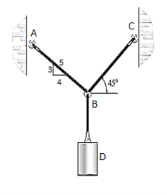
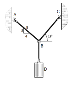
Q13) Determine the tension that will be there in cables BA and BC necessary to support the 60-kg cylinder in Fig. Below.
A13)
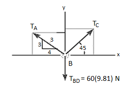
The first step involves drawing the free-body diagram of the given example. As this is two-dimensional structure, we will follow the method mentioned for two-dimensional coplanar structure.
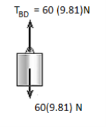
1. Free-Body Diagram. Due to equilibrium, the weight of the cylinder sources the tension in cable TBD = 60*(9.81), Fig. (b). Using the equilibrium at B, forces in BA and BC can be found out. The free-body diagram is shown in Fig. Below (c). The magnitudes of TA and TC are unknown, but their directions are known.


2. Equations of Equilibrium: Applying the equations of equilibrium along the x and y axes, we have
Σ Fx = 0 i.e., TC cos 45° - (4/5) TA = 0
Σ Fy = 0 i.e., TC sin 45° + (3/5) TA - 60(9.81) N = 0
Solving the above equations, we get, TC = 475.66 N = 476 N
Then, substituting this value in above equation,
TA = 420 N
In this way, using the equilibrium equations, we can solve for the unknown force in the given problem.
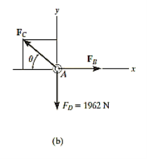
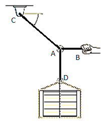
Q14) The 200-kg crate in Fig. Below is suspended using the ropes AB and AC. Each rope can withstand a maximum force of 10 kN before it breaks. If AB always remains horizontal, determine the smallest angle to which the crate can be suspended before one of the ropes breaks.

A14)
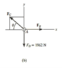
Free-Body Diagram: We will initially understand the equilibrium of ring. There are three forces acting on it, as shown in fig. (b). The magnitude of is equal to the weight of the crate, i.e.,
FD = 200 (9.81) N = 1962 N < 10 kN
Equations of Equilibrium: Applying the equations of equilibrium along the x and y axes,
Σ Fx = 0
i.e. - FC cos θ + FB = 0
Therefore FC = (FB / cos θ)
Σ Fy = 0
i.e., FC sin θ - 1962 N = 0
As seen from the above equations, FC is always greater than FB as cos θ is less than or equal to 1. So, rope AC will reach the max value of tensile force of 10 kN before that of rope AB. Thus, substituting FC = 10 kN in the above equations, we get
[10(103) N] sin θ - 1962 N = 0
Thus, θ = 11.30
The force developed in rope AB can be obtained by substituting the values for θ and FC into Equations mentioned above.
We get, FB = 9.81 kN.
In this way, using equations of equilibrium and free-body diagrams, we can calculate unknown quantities of the given problem.
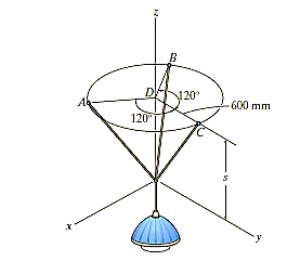
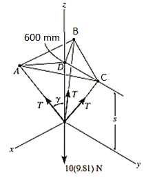
Q15) The 10-kg lamp in Fig. Below is suspended from the three equal-length cords. Find the smallest vertical distance s from the ceiling if force built in cord is not to go beyond 50 kN.
A15)
For solving these three-dimensional numerical, we will follow the same procedure mentioned above.
Free-Body Diagram: Because of symmetry, the distance are as  mm. It follows that from Σ Fx = 0 and Σ Fy = 0, the tension T in each cord will be the same. Also, the angle between z axis and every cord is
  .
.
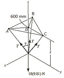
Equation of Equilibrium: Applying the equilibrium equation along the z-axis, with T = 50 N, we have
Σ Fz = 0;
3[(50 N) cos  ] - 10(9.81) N = 0
 = cos-1 (98.1 / 150)
= 49.160
Now,
By geometry shown in free-body diagram,
Tan 49.160 = (600 / s)
s = 519 mm
In this way, three-dimensional problems are solved using equations of equilibrium.
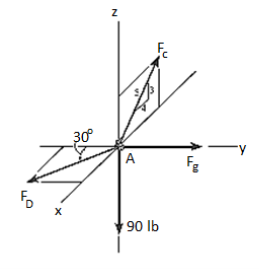
Q16) A 90-lb load is being suspended from a hook as shown in Fig. Below. If the load is being supported by two cables and a spring having a stiffness of k = 500 lb/ft, find the force in the cables and the stretch of the spring for equilibrium. Cable AD lies in the x–y plane and cable AC lies in the x–z plane.

A16)
Initially, force in spring is determined to determine stretching of spring.
Free-Body Diagram. A point is chosen for all analysis as all the points are concurrent here. The free-body diagram for the problem is shown in Fig. Below.
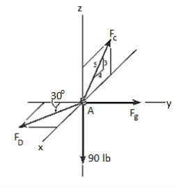
Equations of Equilibrium. We can resolve each force in x, y and z components, and so we can use three scalar equations of equilibrium. Considering components directed along each positive axis as “positive,” we have
Σ Fx = 0
FD sin 30° - (4/5) FC = 0
Σ Fy = 0
-FD cos 30° + FB = 0
Σ Fz = 0
(3/5) FC – 90 lb = 0
Thus, solving the above-mentioned equations, we get,
FC = 150 lb
FD = 240 lb
FB = 207.8 lb
The stretch of the spring is therefore
FB = ksAB
207.8 lb = (500 lb/ft) (sAB)
sAB = 0.416 ft
Thus, the method discussed earlier can be followed as shown in the examples for finding out the unknown quantities in two- and three-dimensional problems using equations of equilibrium.
Unit - 1
Important Vector Quantities
Q1) Explain Moment of a Force about a Specified Axis.
A1)
Sometimes, the moment produced by a force about a specified axis must be determined. For example, suppose the lug nut at O on the car tire in Fig. Above needs to be loosened. The force applied to the wrench will create a tendency for the wrench and the nut to rotate about the moment axis passing through O; however, the nut can only rotate about the y axis. Therefore, to determine the turning effect, only the y component of the moment is needed, and the total moment produced is not important. To determine this component, we can use either a scalar or vector analysis.
Scalar Analysis. To use a scalar analysis in the case of the lug nut in Fig. Above, the moment arm perpendicular distance from the axis to the line of action of the force is dy = d cos  . Thus, the moment will be
MOy = F (d cos )
)
Vector Analysis: To find the moment of force F in above figure about the y axis using a vector analysis, we must first determine the moment of the force about any point O on the y axis by applying MO = r x F. The component My along the y axis is the projection of MO onto the y axis. It can be found using the dot product discussed above, so that My = j*MO = j*(r x F) where j is the unit vector for the y axis.
We can generalize this approach by letting ua be the unit vector that specifies the direction of the axis shown in Fig. 4–21. Then the moment of F about the axis is

This combination is referred to as the scalar triple product. If the vectors are written in Cartesian form, we have


Equivalent Moment:
The equivalent moment acting on a system of forces can be calculated as illustrated in the following examples:
Q2) A force of 15 N is applied perpendicular to the edge of a door 0.8 m wide as shown in Fig. Below. Find the moment of the force about the hinge.
A2)
Given: Force applied (P) = 15 N and width of the door (l) = 0.8 m
Moment when the force acts perpendicular to the door as shown in fig.
We know that the moment of the force about the hinge is given as,
MO = P × l = 15 × 0.8 = 12.0 N-m
If the force is to be applied at a particular angle according to fig. Below,
Then the calculations are done in following procedure.
As the force applied in the question above is inclined at an angle of 600 with the horizontal, we can calculate the moment of force by two methods, either by finding out the perpendicular distance between the hinge and the line of action of the force as shown in Fig. (a) or by finding out the vertical component of the force as shown in Fig. (b) below.
From the geometry of Fig. (a), we find that the perpendicular distance between the line of action of the force and hinge,
OC = OB sin 60° = 0.8 × 0.866 = 0.693 m
∴ Moment = 15 × 0.693 = 10.4 N-m
In the second case, we know that the vertical component of the force
= 15 sin 60° = 15 × 0.866 = 13.0 N
∴ Moment = 13 × 0.8 = 10.4 N-m
Q3) Write the properties of Couple.
A3)
1. Two unlike parallel, non-collinear forces of same magnitude will form couple.
2. Resultant of couple is always zero.
3. Moment of couple is product of one of the forces & lever arm of couple.
M = F xd
Lever arm of couple = ḻlar distance between couple forces.
4. Couple cannot be balanced by single force.
5. Couple can be balanced only by another couple of opposite nature.
6>. Moment of couple is independent of moment centre. i.e. Ref. Point is not required to take moment of couple.
Q4) A force of 15 N is applied at an angle of 600 to the edge of door as shown in figure. Find the moment of this force.

A4)
Resolving force at point B & then taking the moment about point O,
M0 = (15 Cos 60 x 0) + (15 Sin 60 x 0.8)
= 0 + 10.39
M0 = 10.39 N.m
Q5) A 90 N force is applied to the control rod AB. Determine moment of this Force about point B.
A5)
As we don’t know perpendicular distance betn force & point ‘ B ’, Let us resolve the force into two components.
X – Component of force
Fx = 90 Cos 25 = 81.567 N
Y – Component of force
Fy = 90 Sin 25 = 38.036
Now taking moments about point B.
MB = [Fx x (3 Sin 65)] - [Fy x (3 Cos 65)]
MB = (81.65 x 2.72) – (38.036 x 1.27)
= 221.843 – 48.31
MB = 173.53 N.m
Q6) Determine the resultant of the system of forces acting on a beam as shown in figure.

A6)
Above Force system is Non concurrent force system.
Resolving the forces horizontally,
∑ Fx = - 20 Cos 60 = - 10 KN = 10 KN (toward left)
Resolving forces vertically,
∑Fy = - 20 – 30 – 20 Sin 60
= - 67.32 KN
∑Fy = 67.32 KN (downwards)
Resultant, R = √ (∑ Fx) 2 + (∑Fy) 2 = √10 2 + 67.322
R = 68.06 KN
Direction of Resultant,
Tanα = ∑Fy / ∑ Fx = 67.32 / 10.00
α = 81.550
Now taking moment about point A & using Varignon’s theorem.
∑MA = Moment of resultant A
(20 x 1.5) + (30 x 3) + (20 Sin 60 x 6) = (∑ Fx x 0 ) + (∑Fyx X)
223.92 = 67.32 x X
X = 223.92 / 67.32 = 3.326 m from point A
Q7) For a given force system, find the resultant in magnitude & direction. Also find the location of Resultant.

A7)

Resolving forces horizontally,
∑ Fx = - 15 + 25 Cos 40 = 4.15 N (toward right)
Resolving forces vertically,
∑Fy = 25 Sin 40 – 10
= 6.07 n (upward)
R = √(∑ Fx) 2 + (∑Fy)2
= √4.152 + 6.072
R = 7.35 N
Tanα = ∑Fy / ∑ Fx = 6.07 / 4.15
α= 55.640 - - - Angle made by resultant
To find exact position of R, let x is the perpendicular distance betn R & point B.
Using Varignon’s theorem at point B.
R x X = ∑MB
= (10 x 150) – (15 x 150 Sin 50) + ( 25 x 375 ) – ( 6.25 x 1000 )
= 1500 – 1723.6 + 9375 – 6250
= 2901.4 N.mm (clockwise)
x = 2901.4 / R
= 2901.4 / 7.35
x = 394.75 mm from point B.
Q8) Find resultant moment of two couples for the loading as shown in Fig
A8)
Moment of 50 N couple is clockwise,
= 50 x 1
= 50 N.m
Moment of 100 N couple is also clockwise
= 100 x 0.8 = 80 N.m.
Resultant Moment = 50 + 80 = 130 N.m
Q9) Find the resultant and its point of application on y – axis for the force system acting on Triangular plate as shown in fig.
A9)
θ = tan-1 (3/4)
= 36.860 with Horizontal
Resolving forces in x & y dirn
∑ Fx = 20 – 50 Cosθ
= 20 – 50 Cos 36.86
= - 20 N
= 20 N
∑Fy = - 30 + 50 Sin 36.86
= 0.00007
≈ 0
R = √(∑ Fx) 2 + (∑Fy)2
= 20 N toward left (as ∑ Fy = 0 )
Let us apply Varignons theorem at point B
∑MB = R.x
( 30 x 4 ) = Rx
Rx = -120 N.m = 120 N.m
As moment of Resultant is negative i.e. it is anticlockwise
-Rx = -120
X = -120 / -20 = 6 m
X = 6 m from point B and it will be above point. B to create anticlockwise moment.
Q10) If the resultant moment about point A is 4800 Nm clockwise, determine the magnitude of F3 if F1 = 300 N and F2 = 400 N.
A10)
Given: Resultant Moment = 4800 N.m
Let us apply Varignon’s theorem at point A,
∑MB = (R.x )
[(300 60) x 2] + [(400 Sin 60) x 5] + [(F3 Sin 53.13 x 5)] – [(F3 Cos 53.13) x 4] = 4800
519.62 + 1732.05 + 3.99 F3 – 2.4 F3 = 4800
2251.67 + 1.59F3 = 4800
F3 = 2548.33 / 1.59 F3 = 2548.33 / 1.6
OR
F3 = 1602.72 NF3 = 1592.7 N
Q11) The three forces shown in Fig. Create a vertical resultant acting through point B. If P = 361 N, compare the values of T and F.

A11)
From given figure,
1. Angle made by Force P is, = tan-1 (3/3) = 450 with Horizontal
2. Angle made by Force F is, = tan-1 (1/3) = 18.430 with Horizontal
3. Angle made by Force T is, = tan-1 (3/1) = 71.560 with Horizontal

Resolving forces along x & y dirn,
As Resultant is vertical, let it is upward, then
∑ Fx = 0& ∑Fy = R
∑ Fx = P Cos 45 + F Cos 18.43 – T Cos 71.56
0 = 361 Cos 45 + F Cos 18.43 – T Cos 71.56
0 = 255.26 + 0.95 F – 0.32 T
0.95 F – 0.32 T = - 255.26 . . . . (1)
∑Fy = P Sin 45 – F Sin 18.43 + T Sin 71.56
R = 361 Sin 45 – F Sin 18.43 + T Sin 71.56
R = 255.26 – 0.32 F + 0.95 T …… (2)
Now as it is given that Resultant acts at point B, let us apply Varignon’s theorem at point B.
∑MB = R.x
But as R is acting at B point, its perpendicular distance from point B itself will be zero.
∑MB = R.x
(P Cos 45 x 1) – (P Sin 45 x 2) + (T Cos 71.56 x 1) – (T Sin 71.56 x 1) – (F Cos 18.43 x 1) + (F Sin 18.43 x 2) = R x 0
As P = 361 N
-255.26 – (255.26 x 2) + 0.32 T – 0.95 T – 0.95 F + (0.32 F x 2) = 0
-765.78 + 0.32 T – 0.95 T – 0.95 F + 0.64 F = 0
-765.78 – 0.63 T – 0.31 F = 0
– 0.31 F – 0.63 T = 765.78 . . . . (3)
Solving equation (1) and (3) simultaneously

F = -581.716 N &
T = -929.282 N
Q12) Determine the resultant of four forces tangent to the circle of radius 1.5 m as shown. Determine its location w.r.t. ‘O’.
A12)
Resolving forces in X and Y direction,
∑ Fx = 24 - 16 Cos 45
= 12.69 KN ( )
∑Fy = -12 + 8 – 16 Sin 45
= -15.31 kN
= 15.31 kN ( )
Resultant R = √(∑ Fx) 2 + (∑Fy)2
= √ 12.69 2 + (-15.31)2
R = 19.88 kN
Direction of Resultant,
α = tan-1(∑Fy / ∑ Fx)
α = tan-1(15.31 / 12.69)
α = 50.350in 4th quadrant
To know exact location of Resultant, let us apply Varignon’s theorem at point O.
∑MO = R.x
-(12 x 1.5) + (24 x 1.5) – (8 x 1.5) + (16 x 1.5) = (19.88 x X)
30 = R.x
As product of R.x is positive it means moment of Resultant is positive. To create positive clockwise moment of Resultant it must be acting on Right side of O (in 4th quadrant).
30 = 19.88 x X
X = 1.51 m from O on the right hand side.
Q13) Determine the tension that will be there in cables BA and BC necessary to support the 60-kg cylinder in Fig. Below.
A13)
The first step involves drawing the free-body diagram of the given example. As this is two-dimensional structure, we will follow the method mentioned for two-dimensional coplanar structure.
1. Free-Body Diagram. Due to equilibrium, the weight of the cylinder sources the tension in cable TBD = 60*(9.81), Fig. (b). Using the equilibrium at B, forces in BA and BC can be found out. The free-body diagram is shown in Fig. Below (c). The magnitudes of TA and TC are unknown, but their directions are known.
2. Equations of Equilibrium: Applying the equations of equilibrium along the x and y axes, we have
Σ Fx = 0 i.e., TC cos 45° - (4/5) TA = 0
Σ Fy = 0 i.e., TC sin 45° + (3/5) TA - 60(9.81) N = 0
Solving the above equations, we get, TC = 475.66 N = 476 N
Then, substituting this value in above equation,
TA = 420 N
In this way, using the equilibrium equations, we can solve for the unknown force in the given problem.
Q14) The 200-kg crate in Fig. Below is suspended using the ropes AB and AC. Each rope can withstand a maximum force of 10 kN before it breaks. If AB always remains horizontal, determine the smallest angle to which the crate can be suspended before one of the ropes breaks.
A14)
Free-Body Diagram: We will initially understand the equilibrium of ring. There are three forces acting on it, as shown in fig. (b). The magnitude of is equal to the weight of the crate, i.e.,
FD = 200 (9.81) N = 1962 N < 10 kN
Equations of Equilibrium: Applying the equations of equilibrium along the x and y axes,
Σ Fx = 0
i.e. - FC cos θ + FB = 0
Therefore FC = (FB / cos θ)
Σ Fy = 0
i.e., FC sin θ - 1962 N = 0
As seen from the above equations, FC is always greater than FB as cos θ is less than or equal to 1. So, rope AC will reach the max value of tensile force of 10 kN before that of rope AB. Thus, substituting FC = 10 kN in the above equations, we get
[10(103) N] sin θ - 1962 N = 0
Thus, θ = 11.30
The force developed in rope AB can be obtained by substituting the values for θ and FC into Equations mentioned above.
We get, FB = 9.81 kN.
In this way, using equations of equilibrium and free-body diagrams, we can calculate unknown quantities of the given problem.
Q15) The 10-kg lamp in Fig. Below is suspended from the three equal-length cords. Find the smallest vertical distance s from the ceiling if force built in cord is not to go beyond 50 kN.

A15)
For solving these three-dimensional numerical, we will follow the same procedure mentioned above.
Free-Body Diagram: Because of symmetry, the distance are as  mm. It follows that from Σ Fx = 0 and Σ Fy = 0, the tension T in each cord will be the same. Also, the angle between z axis and every cord is
  .
.
Equation of Equilibrium: Applying the equilibrium equation along the z-axis, with T = 50 N, we have
Σ Fz = 0;
3[(50 N) cos  ] - 10(9.81) N = 0
 = cos-1 (98.1 / 150)
= 49.160
Now,
By geometry shown in free-body diagram,
Tan 49.160 = (600 / s)
s = 519 mm
In this way, three-dimensional problems are solved using equations of equilibrium.
Q16) A 90-lb load is being suspended from a hook as shown in Fig. Below. If the load is being supported by two cables and a spring having a stiffness of k = 500 lb/ft, find the force in the cables and the stretch of the spring for equilibrium. Cable AD lies in the x–y plane and cable AC lies in the x–z plane.

A16)
Initially, force in spring is determined to determine stretching of spring.
Free-Body Diagram. A point is chosen for all analysis as all the points are concurrent here. The free-body diagram for the problem is shown in Fig. Below.
Equations of Equilibrium. We can resolve each force in x, y and z components, and so we can use three scalar equations of equilibrium. Considering components directed along each positive axis as “positive,” we have
Σ Fx = 0
FD sin 30° - (4/5) FC = 0
Σ Fy = 0
-FD cos 30° + FB = 0
Σ Fz = 0
(3/5) FC – 90 lb = 0
Thus, solving the above-mentioned equations, we get,
FC = 150 lb
FD = 240 lb
FB = 207.8 lb
The stretch of the spring is therefore
FB = ksAB
207.8 lb = (500 lb/ft) (sAB)
sAB = 0.416 ft
Thus, the method discussed earlier can be followed as shown in the examples for finding out the unknown quantities in two- and three-dimensional problems using equations of equilibrium.