Unit - 2
Rolling loads on simply supports beams
Q1) What is rolling load?
A1)
Loads which roll over the given structural detail from one quit to the every other quit. In a rolling load most shears force, bending moments.
Example: train on the railway track, automobiles at the bridges or roads are rolling loads etc.
Rolling loads there are 3 types:
1. Single factor rolling load
2. Uniformly distributed load
3. Two factor rolling load
Uniformly distributed load there are main types: 1) Longer than span 2) Smaller than span
ILD for beams and rolling load:
It is a diagram which shows version of AF, SF and BM on the sort of characteristic at a unique section for numerous function of moving load.
It is a diagram which indicates variation of AF, SF and BM on any such function at a particular section for various position of moving load.
Q2) How to find value of function from ILD
A2)
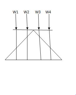
i) Structure subjected to point loads

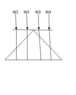
Meg. Of function = W1Y1 +W2Y2 +W3Y3+W4Y4
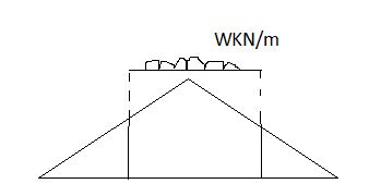
Ii) Structure subjected to udl
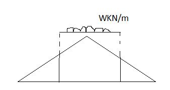
Magnitude of function = {Area of ILD under UDL} 𝓌
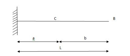
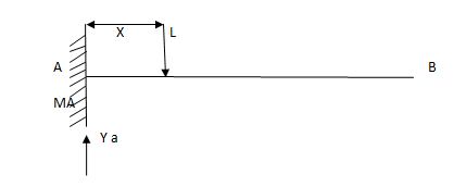
i)VA =? (ii) MA=? (iii) SF = (iv) BM =
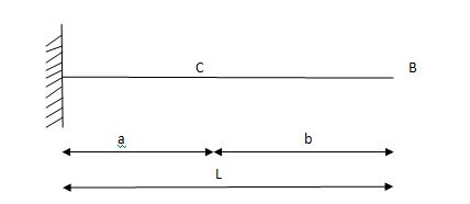
1) ILD’s for VA & MA
Consider unit load at a distance
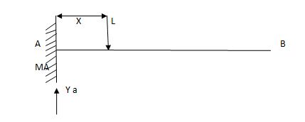
MA = MA -1 (x) =0
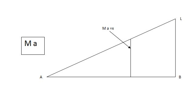
MA =x
X VA MA
0 1 0
L 1 0
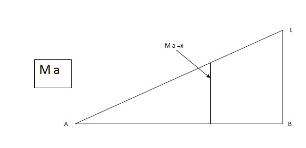
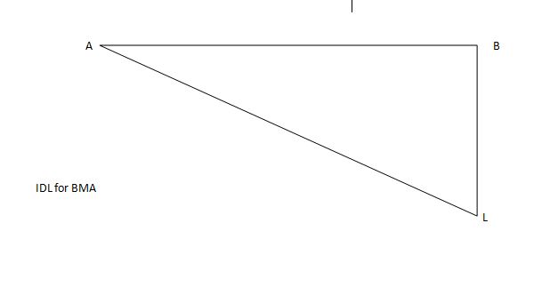
ILD for bending moment at A is as below
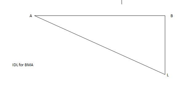
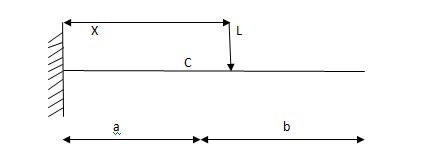
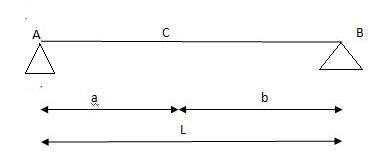
ILD for shear force & BM at ‘C’

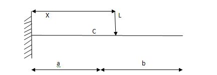
SF@ c =0, BMC =0
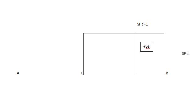
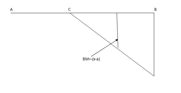
SFC =1; BMC = -1 (x-a)
For x = a; BM@ c =0 X = L;
BMC = -1(1-a) c b
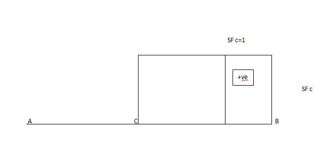
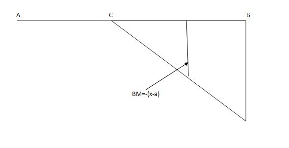
2)
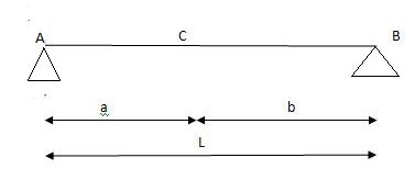
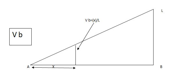
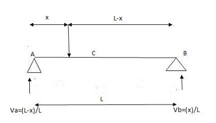
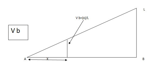
1) ILD’s for VA& VB
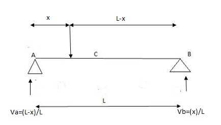
x VA VB
0 1 0
L 0 1
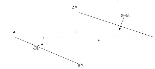
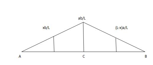
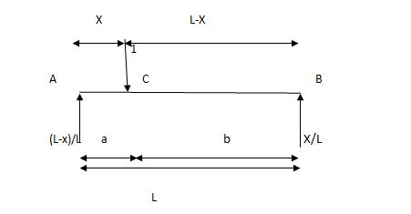
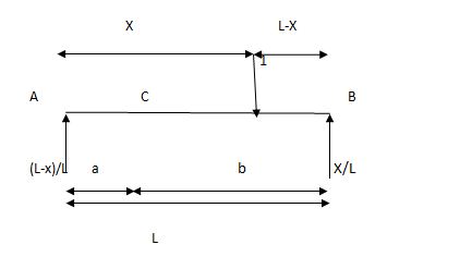
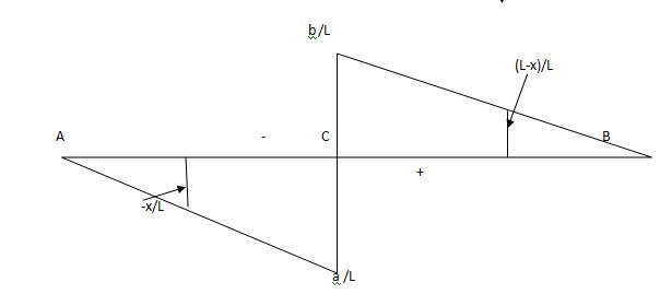
2) SF c & BM c
1)
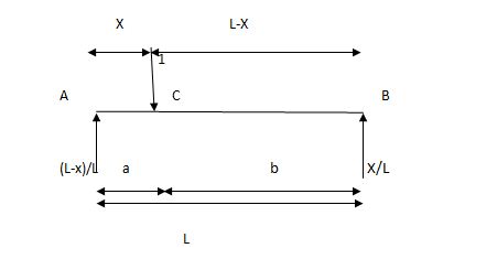
2)
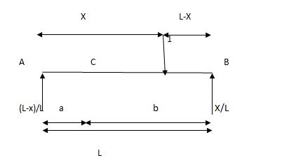
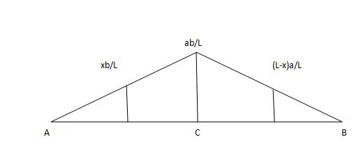
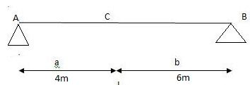
Q3) A simply supported beam subjected to moving udl

A3)
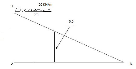
1)
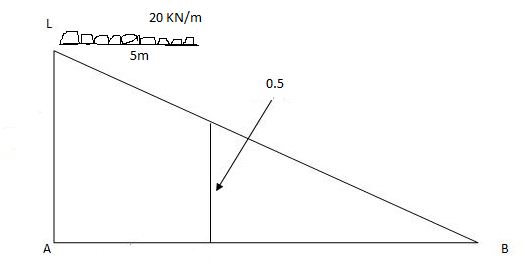
VA max = (20) = 75 KN
VA max = 20 = 75 KN
Note:-
Absolute maximum shear force is nothing but greater 07 VA, max & VB, max
Abs. Max SF = 75 KN
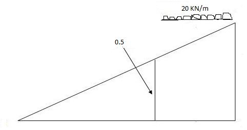
2)
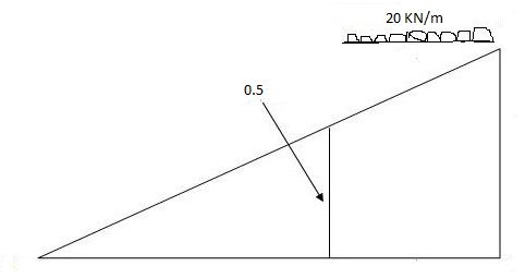
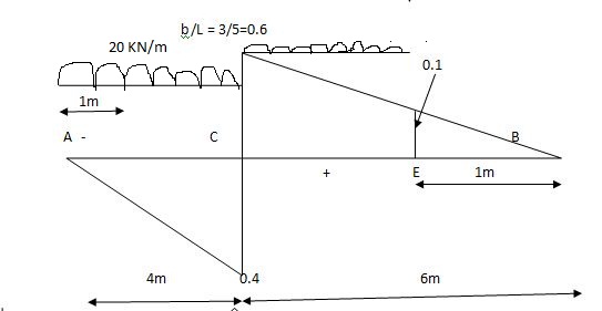
Max.(–ve) SFc = (-) (20)
= ( ) 16KN
Max. +ve SF c =
=35KN
Max .SFc = 35 KN
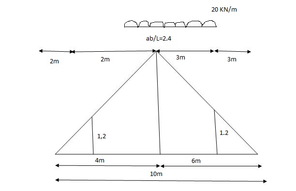
= x = 2m
= (5) (20) =180 KNm
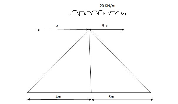
Abs. Max BM = (5) (20) =187.5 KNm
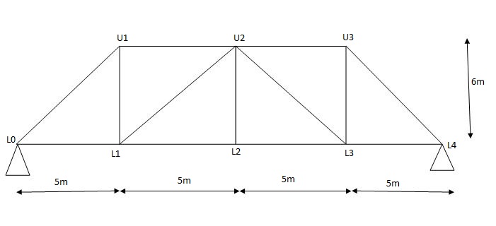
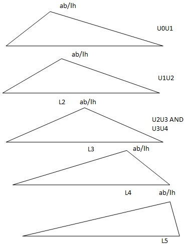
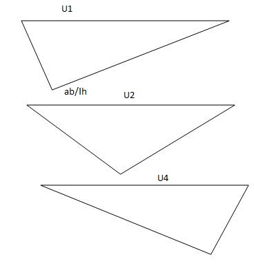
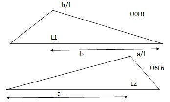
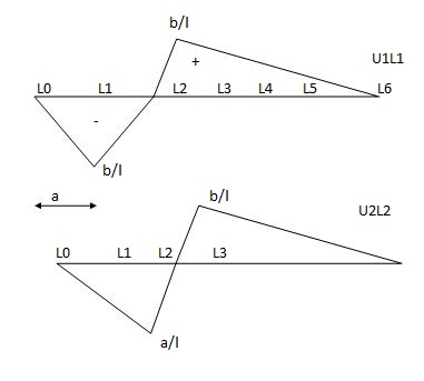
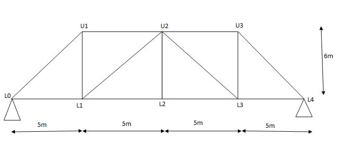
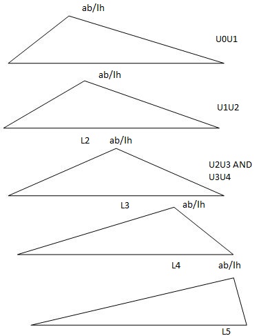
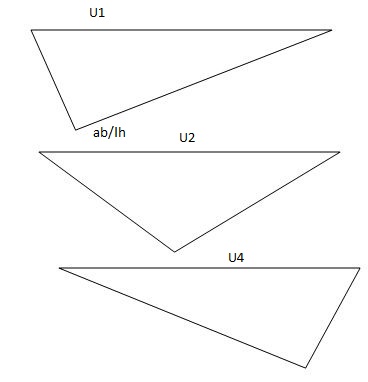
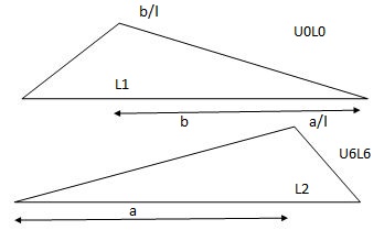
Diagonal members design
Top camp
Q4) What is influence line?
A4)
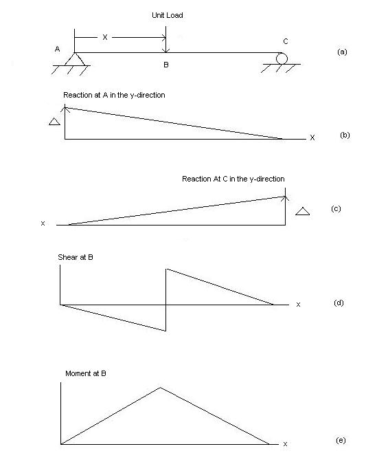
An influence line for a given characteristic, which includes a reaction, axial pressure, shear pressure, or bending moment, is a graph that indicates the version of that characteristic at any given factor on a shape because of the software of a unit load at any factor on the shape. Influence line is additive and scalar. The scaled most and minimal are the essential magnitudes that need to be designed for within side the beam or truss.
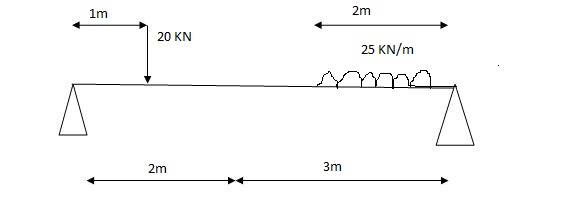
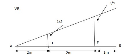
Q5) A simply supported beam is subjected to loads as shown in fig.
Using influence lines find
Support reactions
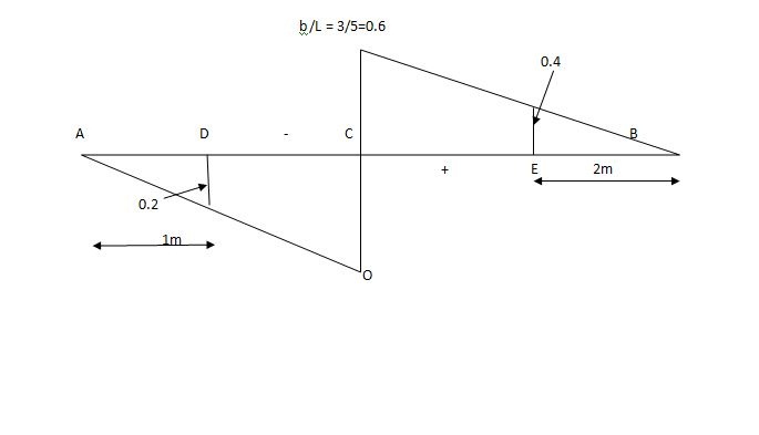
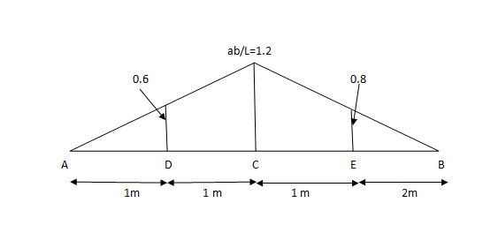
Shear force & bending moment at ‘C’
A5)
1) VA& VB
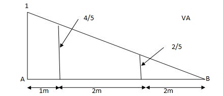
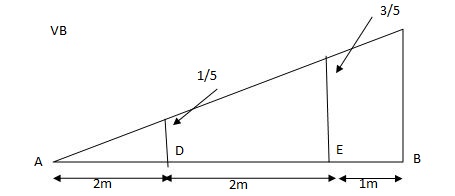
VA = 20 + 25 1 = 16 + 10 = 26 KN
VB = 20 + 25 + = 4 + 40 = 44 KN
=0.6
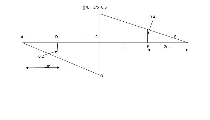
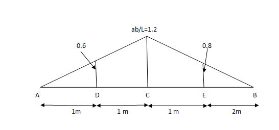
SF@ c = 20 (-0.2) + 25= 5KN
BM@ c = 20 (0.6) + (2 0.8) (25)
= 32 KN. M
Q6) What is maximum bending moment envelope?
A6)
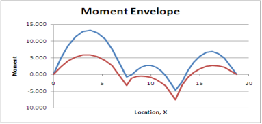
The second or moment envelope curve defines the intense boundary values of bending second alongside the beam because of essential placements of layout stay loading.
Note that no person second diagram defines the top or decrease certain throughout the whole 3 spans. It has been essential to do all six analysis.
Figure indicates simply the top and decrease bounds for second alongside the beam.
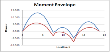
This is a second envelope diagram. Note that the instant at the beam will always be among the top and decrease bounds. These are the crucial values wanted for design.
Similar methods are taken the increase envelopes for different load outcomes including shear or deflection.
The fundamental steps are the same:
Identify the important load instances the usage of have an effect on lines.
Analyze every of the burden instances
For every place alongside the member, decide the higher and decrease sure values and graph them.
By a few astute commentary it's miles feasible to provide you with different methods to the problem. One such technique is offered with inside the subsequent section.
Q7) What steps followed for bending moments and shear forces in simply supported beam?
A7)
When solving for reactions, the following steps are recommended:
- Draw the beam free body diagram
- Replace the uniform distributed load (if any) with the equivalent point load
- Solve ΣMA = 0 (sum of moments about support A). This will give you RB (reaction at support B).
- Solve ΣMB = 0. This will give you RA.
- Using RA and RB found at steps 3 and 4 check if ΣV = 0 (sum of all vertical forces) is satisfied.
- Note that steps 4 and 5 can be reversed.
- For a cantilever beam use ΣV = 0 to find the vertical reaction at the wall and ΣMwall = 0 to find the moment reaction at the wall. There is no other equation to validate your results.
Q8) What is shear forces and bending moment’s diagrams?
A8)
- The shear pressure at any phase of a beam can be observed with the aid of using summing all of the vertical forces to the left or to the proper of the phase below consideration.
- Similarly, the bending second at any phase of a beam can be observed with the aid of using including the moments from the left or from the proper of the phase taken into consideration.
- The second’s pivot factor is the area below consideration. By convention, inner shearing forces performing downward are taken into consideration positive. They counteract upward outside forces.
- This is visually simpler than following the signal convention.
- Clockwise moments, conventionally, are taken into consideration bad at the same time as counter-clockwise moments are taken into consideration positive.
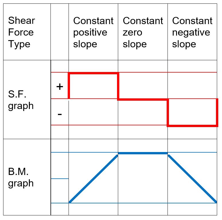
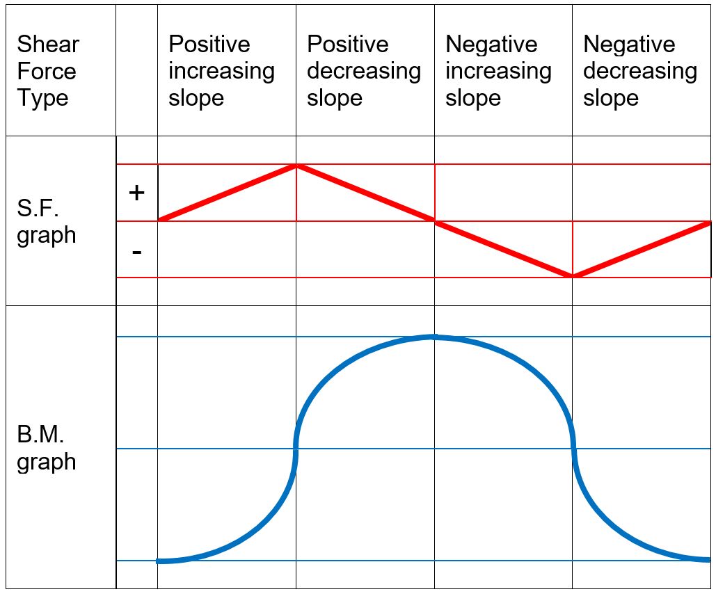
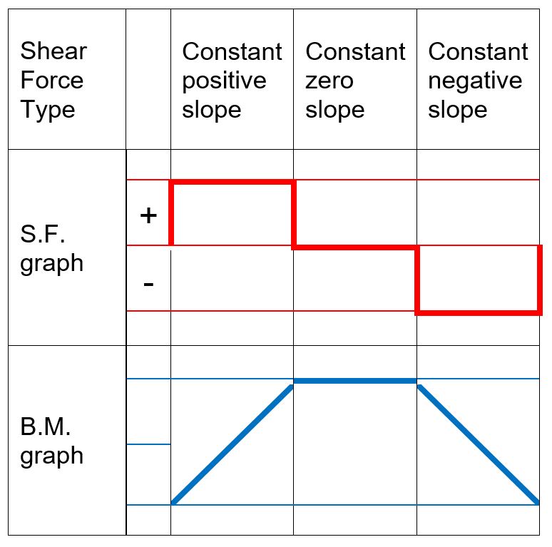
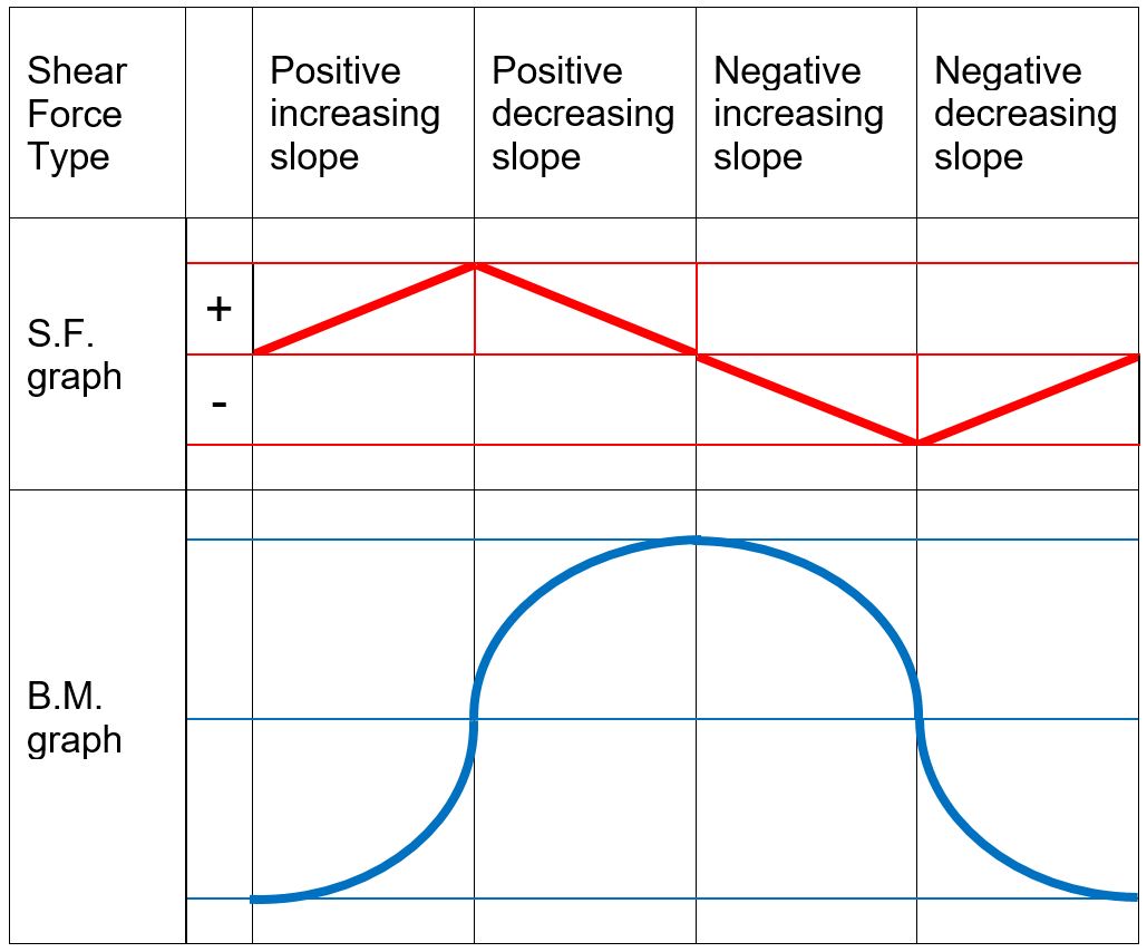
- When representing the bending second variation, seek advice from the subsequent desk displaying qualitative bending second curves depending on the form of the shear pressure graphs.
 .
.
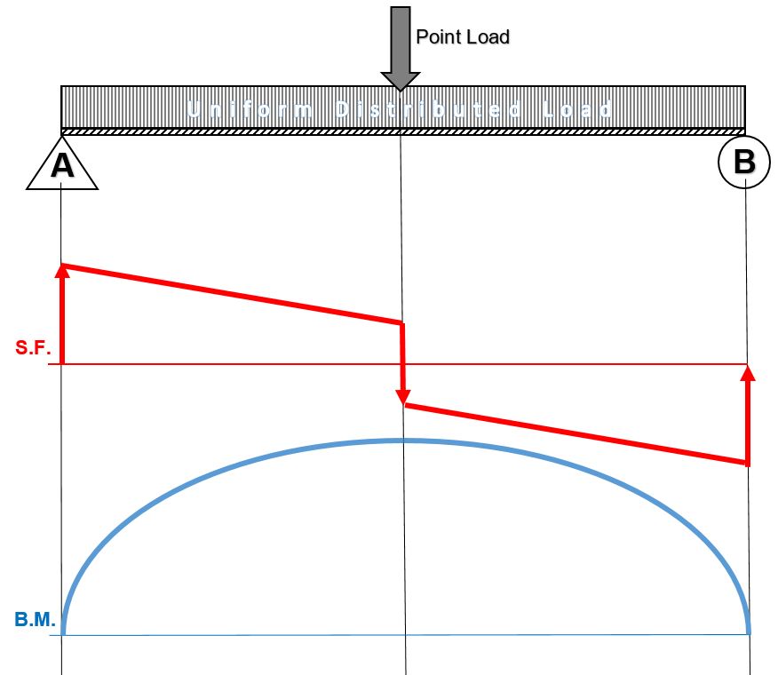
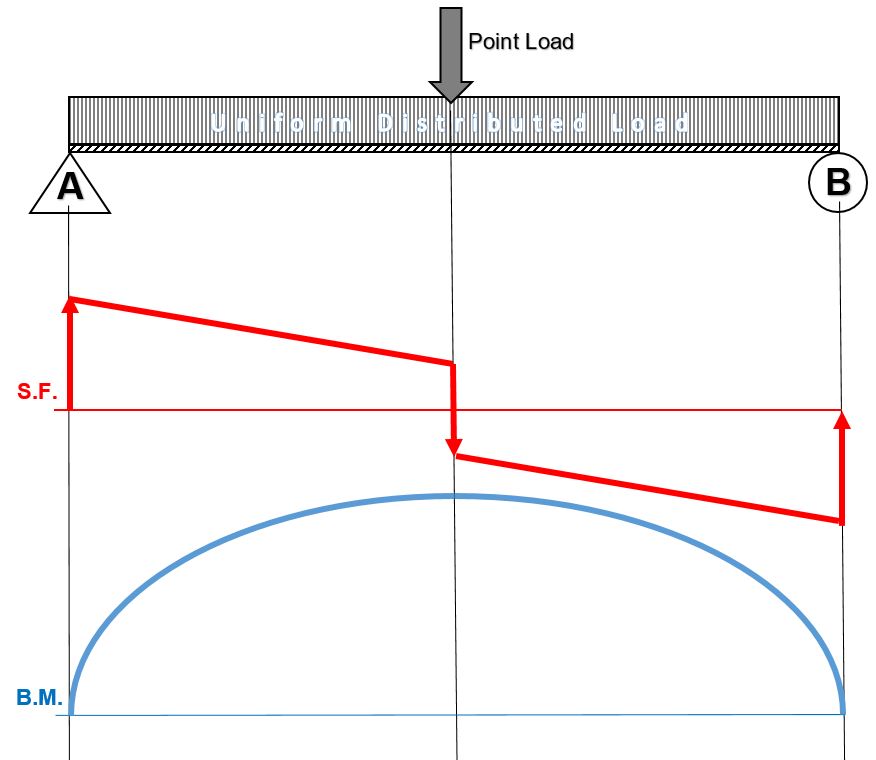
When drawing the shear force and bending moment diagrams, while the sign convention is important, consistency is crucial. For instance, consider a simple beam loaded with a point load applied on a UD load. Starting the diagrams at support A, looking towards the page, will generate the following:
- Now, flip the beam horizontally 180º (or change the observation point, looking at the beam from the opposite side) and draw the diagrams, starting from the same point A. The diagrams will appear as follows:
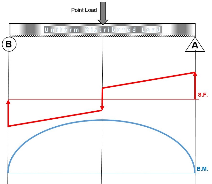
Note that, while the shear force diagrams appeared to be mirrored images (flipped horizontally), the bending moment diagram is not affected. Additionally, the most important result of this analysis, illustrates that maximum shear force and bending moment magnitudes will always be the same
Q9) Explain only shear Forces Diagrams
A9)
- At the ends of a genuinely supported beam the shear pressure is 0.
- At the wall of a cantilever beam the shear pressure equals the vertical response on the wall.
- At the beam’s loose quit the shear pressure is 0.
- On any beam phase wherein no hundreds are implemented, the shear pressure stays constant (horizontal line).
- A factor load or response on a shear pressure diagram generates an abrupt extrude with inside the graph, with inside the course of the implemented load.
- A uniform dispensed load appearing on a beam is represented through a directly line shear pressure with a terrible or high-quality slope, identical to the weight in step with unit length.
Q10) What is bending moments diagram?
A10)
- At the ends of a genuinely supported beam the bending moments are 0.
- At the wall of a cantilever beam, the bending second equals the instant response.
- At the loose quit, the bending second is 0.
- At the place wherein the shear pressure crosses the 0 axis the corresponding bending second has a most value.
- The form of the bending second curve among factors at the beam is as proven with inside the above tables.
- The extrude in bending second among factors at the beam equals the vicinity below the shear pressure diagram among the identical factors.
Q11) What is cantilever beams?
A11)
- A cantilever is an inflexible structural detail that extends horizontally and is supported at best one quit. Typically it extends from a flat vertical floor together with a wall, to which it have to be firmly attached.
- Like different structural elements, a cantilever may be fashioned as a beam, plate, truss, or slab. When subjected to a structural load at it’s far, unsupported quit, the cantilever consists of the burden to the help wherein it applies a shear strain and a bending moment. Cantilever production permits overhanging systems without extra help.
- Cantilevers are broadly located in production, considerably in cantilever bridges and balconies (see corbel).
- In cantilever bridges, the cantilevers are generally constructed as pairs, with every cantilever used to help one quit of a valuable section. The Forth Bridge in Scotland is an instance of a cantilever truss bridge.
- A cantilever in a historically wood framed constructing is known as a jetty or for eBay. In the southern United States, anincidental barn kind is the cantilever barn of log production. Temporary cantilevers are regularly utilized in production.
- The in part built shape creates a cantilever, however the finished shape does now no longer act as a cantilever.
- This may be very beneficial while transient supports, or false work, can't be used to help the shape at the same time as its miles being constructed (e.g., over a hectic roadway or river, or in a deep valley).
- Therefore, a few truss arch bridges (see Navajo Bridge) are constructed from every facet as cantilevers till the spans attain every different and are then jacked aside to strain them in compression earlier than eventually joining.
- Nearly all cable-stayed bridges are constructed the usage of cantilevers as that is certainly considered one among their leader advantages. Many field girder bridges are constructed segmentally, or in quick pieces.
- This kind of production lends itself properly to balanced cantilever production wherein the bridge is constructed in each instructions from an unmarried help.
Q12) Give condition of cantilever Beam - Single Load at the End
A12)

Maximum Reaction Force
At the fixed end can be expressed as:
RA = F (1a)
Where
RA = reaction force in A (N, lb)
F = single acting force in B (N, lb)
Maximum Moment
At the fixed end can be expressed as
Mmax = MA
= - F L (1b)
Where
MA = maximum moment in A (Nm, Nmm, lb in)
L = length of beam (m, mm, in)
Maximum Deflection
At the end of the cantilever beam can be expressed as
δB = F L3 / (3 E I) (1c)
Where
δB = maximum deflection in B (m, mm, in)
E = modulus of elasticity (N/m2 (Pa), N/mm2, lb/in2 (psi))
I = moment of Inertia (m4, mm4, in4)
b = length between B and C (m, mm, in)
Q13) Explain condition of Cantilever Beam - Single Load
A13)
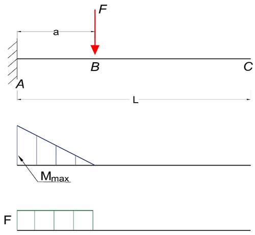
Maximum Reaction Force
At the fixed end can be expressed as:
RA = F (2a)
Where
RA = reaction force in A (N, lb)
F = single acting force in B (N, lb)
Maximum Moment
At the fixed end can be expressed as
Mmax = MA
= - F a (2b)
Where
MA = maximum moment in A (N.m, N.mm, lb.in)
a = length between A and B (m, mm, in)
Maximum Deflection
At the end of the cantilever beam can be expressed as
δC = (F a3 / (3 E I)) (1 + 3 b / 2 a) (2c)
Where
δC = maximum deflection in C (m, mm, in)
E = modulus of elasticity (N/m2 (Pa), N/mm2, lb/in2 (psi))
I = moment of Inertia (m4, mm4, in4)
b = length between B and C (m, mm, in)
Maximum Deflection
At the action of the single force can be expressed as
δB = F a3 / (3 E I) (2d)
Where
δB = maximum deflection in B (m, mm, in)
Maximum Stress
The maximum stress can be calculated by combining 1d and 2b to
σmax = ymax F a / I
Q14) What is overhang beams?
A14)
The beam is a horizontal structural detail made from wood, steel, or concrete that resists the lateral load coming from the superstructure utilizing bending.
It is predicted to resist shear force, lateral force, and bending moments. There are one of a kind sorts of beams like simply supported beams, Cantilever beams, Fixed beams, Continuous beams, Overhanging beams, etc.
The overhanging beam is a form of beam wherein the stop percentage of the beam extends extra from assist.
It is the aggregate of each a cantilever and an actually supported beam. The overhanging beam is secure in case you assemble them with inside the proper way. Otherwise, the beam may also fail.
The overhanging beam is usually used to make balconies or shades. The extension in overhanging beam must be restricted to 1m (3′-3”). If there may be a right structural document suggesting an extension of extra than 1m then it's miles adequate to use.
Q15) Give types of overhanging beam
A15)
a. Single Overhanging Beam
It is an easy form of beam wherein a positive part of the beam is prolonged past the assist at one stop only. It is the merge of actually supported and cantilever beams. For example; a balcony this is being prolonged from the framed structure.
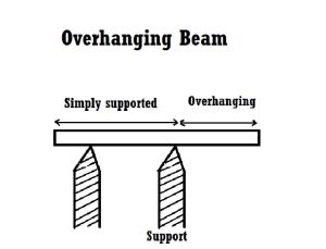
b. Double Overhanging Beam
The overhanging beam wherein a positive part of the beam is prolonged past the assist at each ends is called a double overhanging beam. The load implemented at the striking element is appropriately transferred to the assist (i.e hinge or roller) via way of means of equal bending second.
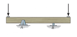
Properties of Overhanging Beam
1. It must have sufficient power to undergo masses performing on it.
2. It must face up to the chemical and weathering agencies.
3. It must be long lasting and sound.
4. It must have a width to intensity ratio of extra than 0.3.
5. Minimum width must be 200mm.
6. The intensity of overhanging must now no longer be extra than 1/four of the clean span.
Q16) Give use, advantages and disadvantages of overhanging beam.
A16)
Uses of Overhanging Beam
An overhanging beam is used in which it isn't always sensible to offer assist to the beam at one stop or each ends.
The overhanging beam is especially encountered in a ground beam that extends past the outdoors wall of a constructing to offer assist to a balcony.
Advantages of Overhanging Beam
1. This beam enables to offer stability to the axial second on the assist of the column.
2. It decreases the one-sided load in a beam.
3. It has low sagging.
4. It is easy to assemble.
Disadvantage of overhanging beam
1. It rises the lifeless load at the structure.
2. It rises the uniaxial second on the assist of the column.
3. Restriction with inside the extension length.
Unit - 2
Unit - 2
Rolling loads on simply supports beams
Q1) What is rolling load?
A1)
Loads which roll over the given structural detail from one quit to the every other quit. In a rolling load most shears force, bending moments.
Example: train on the railway track, automobiles at the bridges or roads are rolling loads etc.
Rolling loads there are 3 types:
1. Single factor rolling load
2. Uniformly distributed load
3. Two factor rolling load
Uniformly distributed load there are main types: 1) Longer than span 2) Smaller than span
ILD for beams and rolling load:
It is a diagram which shows version of AF, SF and BM on the sort of characteristic at a unique section for numerous function of moving load.
It is a diagram which indicates variation of AF, SF and BM on any such function at a particular section for various position of moving load.
Q2) How to find value of function from ILD
A2)
i) Structure subjected to point loads

Meg. Of function = W1Y1 +W2Y2 +W3Y3+W4Y4
Ii) Structure subjected to udl
Magnitude of function = {Area of ILD under UDL} 𝓌
i)VA =? (ii) MA=? (iii) SF = (iv) BM =
1) ILD’s for VA & MA
Consider unit load at a distance
MA = MA -1 (x) =0
MA =x
X VA MA
0 1 0
L 1 0
ILD for bending moment at A is as below
ILD for shear force & BM at ‘C’

SF@ c =0, BMC =0
SFC =1; BMC = -1 (x-a)
For x = a; BM@ c =0 X = L;
BMC = -1(1-a) c b
2)
1) ILD’s for VA& VB
x VA VB
0 1 0
L 0 1
2) SF c & BM c
1)
2)
Q3) A simply supported beam subjected to moving udl
A3)
1)
VA max = (20) = 75 KN
VA max = 20 = 75 KN
Note:-
Absolute maximum shear force is nothing but greater 07 VA, max & VB, max
Abs. Max SF = 75 KN
2)
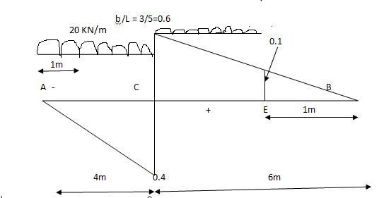
Max.(–ve) SFc = (-) (20)
= ( ) 16KN
Max. +ve SF c =
=35KN
Max .SFc = 35 KN
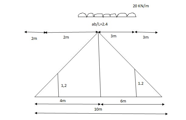
= x = 2m
= (5) (20) =180 KNm
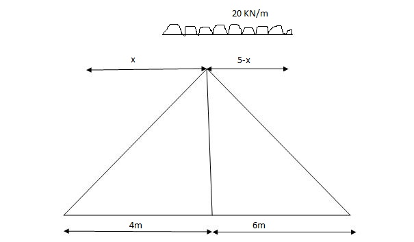
Abs. Max BM = (5) (20) =187.5 KNm
Diagonal members design
Top camp
Q4) What is influence line?
A4)
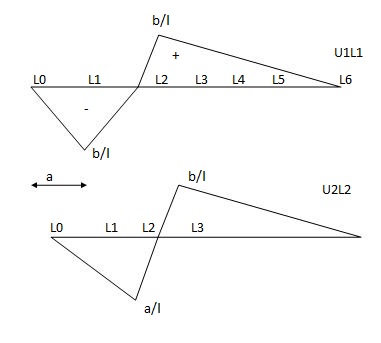
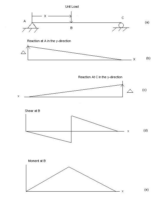
An influence line for a given characteristic, which includes a reaction, axial pressure, shear pressure, or bending moment, is a graph that indicates the version of that characteristic at any given factor on a shape because of the software of a unit load at any factor on the shape. Influence line is additive and scalar. The scaled most and minimal are the essential magnitudes that need to be designed for within side the beam or truss.
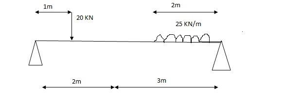
Q5) A simply supported beam is subjected to loads as shown in fig.
Using influence lines find
Support reactions
Shear force & bending moment at ‘C’
A5)
1) VA& VB
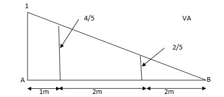
VA = 20 + 25 1 = 16 + 10 = 26 KN
VB = 20 + 25 + = 4 + 40 = 44 KN
=0.6
SF@ c = 20 (-0.2) + 25= 5KN
BM@ c = 20 (0.6) + (2 0.8) (25)
= 32 KN. M
Q6) What is maximum bending moment envelope?
A6)
The second or moment envelope curve defines the intense boundary values of bending second alongside the beam because of essential placements of layout stay loading.
Note that no person second diagram defines the top or decrease certain throughout the whole 3 spans. It has been essential to do all six analysis.
Figure indicates simply the top and decrease bounds for second alongside the beam.
This is a second envelope diagram. Note that the instant at the beam will always be among the top and decrease bounds. These are the crucial values wanted for design.
Similar methods are taken the increase envelopes for different load outcomes including shear or deflection.
The fundamental steps are the same:
Identify the important load instances the usage of have an effect on lines.
Analyze every of the burden instances
For every place alongside the member, decide the higher and decrease sure values and graph them.
By a few astute commentary it's miles feasible to provide you with different methods to the problem. One such technique is offered with inside the subsequent section.
Q7) What steps followed for bending moments and shear forces in simply supported beam?
A7)
When solving for reactions, the following steps are recommended:
- Draw the beam free body diagram
- Replace the uniform distributed load (if any) with the equivalent point load
- Solve ΣMA = 0 (sum of moments about support A). This will give you RB (reaction at support B).
- Solve ΣMB = 0. This will give you RA.
- Using RA and RB found at steps 3 and 4 check if ΣV = 0 (sum of all vertical forces) is satisfied.
- Note that steps 4 and 5 can be reversed.
- For a cantilever beam use ΣV = 0 to find the vertical reaction at the wall and ΣMwall = 0 to find the moment reaction at the wall. There is no other equation to validate your results.
Q8) What is shear forces and bending moment’s diagrams?
A8)
- The shear pressure at any phase of a beam can be observed with the aid of using summing all of the vertical forces to the left or to the proper of the phase below consideration.
- Similarly, the bending second at any phase of a beam can be observed with the aid of using including the moments from the left or from the proper of the phase taken into consideration.
- The second’s pivot factor is the area below consideration. By convention, inner shearing forces performing downward are taken into consideration positive. They counteract upward outside forces.
- This is visually simpler than following the signal convention.
- Clockwise moments, conventionally, are taken into consideration bad at the same time as counter-clockwise moments are taken into consideration positive.
- When representing the bending second variation, seek advice from the subsequent desk displaying qualitative bending second curves depending on the form of the shear pressure graphs.
 .
.
When drawing the shear force and bending moment diagrams, while the sign convention is important, consistency is crucial. For instance, consider a simple beam loaded with a point load applied on a UD load. Starting the diagrams at support A, looking towards the page, will generate the following:
- Now, flip the beam horizontally 180º (or change the observation point, looking at the beam from the opposite side) and draw the diagrams, starting from the same point A. The diagrams will appear as follows:
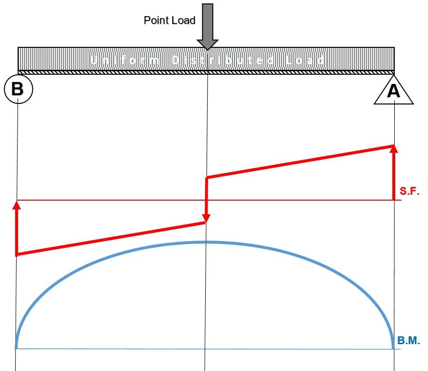
Note that, while the shear force diagrams appeared to be mirrored images (flipped horizontally), the bending moment diagram is not affected. Additionally, the most important result of this analysis, illustrates that maximum shear force and bending moment magnitudes will always be the same
Q9) Explain only shear Forces Diagrams
A9)
- At the ends of a genuinely supported beam the shear pressure is 0.
- At the wall of a cantilever beam the shear pressure equals the vertical response on the wall.
- At the beam’s loose quit the shear pressure is 0.
- On any beam phase wherein no hundreds are implemented, the shear pressure stays constant (horizontal line).
- A factor load or response on a shear pressure diagram generates an abrupt extrude with inside the graph, with inside the course of the implemented load.
- A uniform dispensed load appearing on a beam is represented through a directly line shear pressure with a terrible or high-quality slope, identical to the weight in step with unit length.
Q10) What is bending moments diagram?
A10)
- At the ends of a genuinely supported beam the bending moments are 0.
- At the wall of a cantilever beam, the bending second equals the instant response.
- At the loose quit, the bending second is 0.
- At the place wherein the shear pressure crosses the 0 axis the corresponding bending second has a most value.
- The form of the bending second curve among factors at the beam is as proven with inside the above tables.
- The extrude in bending second among factors at the beam equals the vicinity below the shear pressure diagram among the identical factors.
Q11) What is cantilever beams?
A11)
- A cantilever is an inflexible structural detail that extends horizontally and is supported at best one quit. Typically it extends from a flat vertical floor together with a wall, to which it have to be firmly attached.
- Like different structural elements, a cantilever may be fashioned as a beam, plate, truss, or slab. When subjected to a structural load at it’s far, unsupported quit, the cantilever consists of the burden to the help wherein it applies a shear strain and a bending moment. Cantilever production permits overhanging systems without extra help.
- Cantilevers are broadly located in production, considerably in cantilever bridges and balconies (see corbel).
- In cantilever bridges, the cantilevers are generally constructed as pairs, with every cantilever used to help one quit of a valuable section. The Forth Bridge in Scotland is an instance of a cantilever truss bridge.
- A cantilever in a historically wood framed constructing is known as a jetty or for eBay. In the southern United States, anincidental barn kind is the cantilever barn of log production. Temporary cantilevers are regularly utilized in production.
- The in part built shape creates a cantilever, however the finished shape does now no longer act as a cantilever.
- This may be very beneficial while transient supports, or false work, can't be used to help the shape at the same time as its miles being constructed (e.g., over a hectic roadway or river, or in a deep valley).
- Therefore, a few truss arch bridges (see Navajo Bridge) are constructed from every facet as cantilevers till the spans attain every different and are then jacked aside to strain them in compression earlier than eventually joining.
- Nearly all cable-stayed bridges are constructed the usage of cantilevers as that is certainly considered one among their leader advantages. Many field girder bridges are constructed segmentally, or in quick pieces.
- This kind of production lends itself properly to balanced cantilever production wherein the bridge is constructed in each instructions from an unmarried help.
Q12) Give condition of cantilever Beam - Single Load at the End
A12)
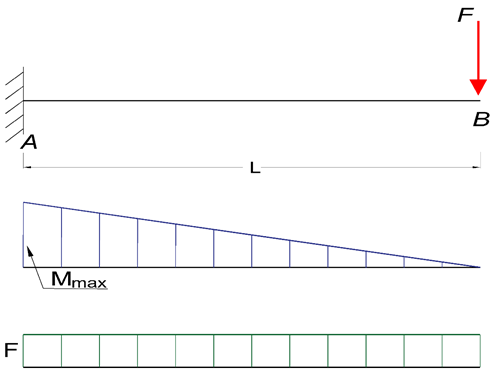
Maximum Reaction Force
At the fixed end can be expressed as:
RA = F (1a)
Where
RA = reaction force in A (N, lb)
F = single acting force in B (N, lb)
Maximum Moment
At the fixed end can be expressed as
Mmax = MA
= - F L (1b)
Where
MA = maximum moment in A (Nm, Nmm, lb in)
L = length of beam (m, mm, in)
Maximum Deflection
At the end of the cantilever beam can be expressed as
δB = F L3 / (3 E I) (1c)
Where
δB = maximum deflection in B (m, mm, in)
E = modulus of elasticity (N/m2 (Pa), N/mm2, lb/in2 (psi))
I = moment of Inertia (m4, mm4, in4)
b = length between B and C (m, mm, in)
Q13) Explain condition of Cantilever Beam - Single Load
A13)
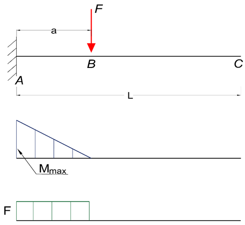
Maximum Reaction Force
At the fixed end can be expressed as:
RA = F (2a)
Where
RA = reaction force in A (N, lb)
F = single acting force in B (N, lb)
Maximum Moment
At the fixed end can be expressed as
Mmax = MA
= - F a (2b)
Where
MA = maximum moment in A (N.m, N.mm, lb.in)
a = length between A and B (m, mm, in)
Maximum Deflection
At the end of the cantilever beam can be expressed as
δC = (F a3 / (3 E I)) (1 + 3 b / 2 a) (2c)
Where
δC = maximum deflection in C (m, mm, in)
E = modulus of elasticity (N/m2 (Pa), N/mm2, lb/in2 (psi))
I = moment of Inertia (m4, mm4, in4)
b = length between B and C (m, mm, in)
Maximum Deflection
At the action of the single force can be expressed as
δB = F a3 / (3 E I) (2d)
Where
δB = maximum deflection in B (m, mm, in)
Maximum Stress
The maximum stress can be calculated by combining 1d and 2b to
σmax = ymax F a / I
Q14) What is overhang beams?
A14)
The beam is a horizontal structural detail made from wood, steel, or concrete that resists the lateral load coming from the superstructure utilizing bending.
It is predicted to resist shear force, lateral force, and bending moments. There are one of a kind sorts of beams like simply supported beams, Cantilever beams, Fixed beams, Continuous beams, Overhanging beams, etc.
The overhanging beam is a form of beam wherein the stop percentage of the beam extends extra from assist.
It is the aggregate of each a cantilever and an actually supported beam. The overhanging beam is secure in case you assemble them with inside the proper way. Otherwise, the beam may also fail.
The overhanging beam is usually used to make balconies or shades. The extension in overhanging beam must be restricted to 1m (3′-3”). If there may be a right structural document suggesting an extension of extra than 1m then it's miles adequate to use.
Q15) Give types of overhanging beam
A15)
a. Single Overhanging Beam
It is an easy form of beam wherein a positive part of the beam is prolonged past the assist at one stop only. It is the merge of actually supported and cantilever beams. For example; a balcony this is being prolonged from the framed structure.
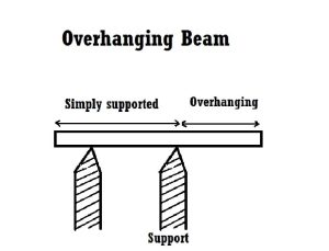
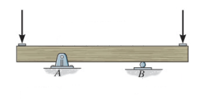
b. Double Overhanging Beam
The overhanging beam wherein a positive part of the beam is prolonged past the assist at each ends is called a double overhanging beam. The load implemented at the striking element is appropriately transferred to the assist (i.e hinge or roller) via way of means of equal bending second.
Properties of Overhanging Beam
1. It must have sufficient power to undergo masses performing on it.
2. It must face up to the chemical and weathering agencies.
3. It must be long lasting and sound.
4. It must have a width to intensity ratio of extra than 0.3.
5. Minimum width must be 200mm.
6. The intensity of overhanging must now no longer be extra than 1/four of the clean span.
Q16) Give use, advantages and disadvantages of overhanging beam.
A16)
Uses of Overhanging Beam
An overhanging beam is used in which it isn't always sensible to offer assist to the beam at one stop or each ends.
The overhanging beam is especially encountered in a ground beam that extends past the outdoors wall of a constructing to offer assist to a balcony.
Advantages of Overhanging Beam
1. This beam enables to offer stability to the axial second on the assist of the column.
2. It decreases the one-sided load in a beam.
3. It has low sagging.
4. It is easy to assemble.
Disadvantage of overhanging beam
1. It rises the lifeless load at the structure.
2. It rises the uniaxial second on the assist of the column.
3. Restriction with inside the extension length.