Unit - 5
Plane Table Surveying & Computation of Area & Volume
Q1) What is plane table surveying?
A1)
Plane Table Surveying
Plane Table Surveying
• Plotting of the plan and area observations may be achieved simultaneously
• Geometrical situations of web website online are manuscript with inside the map sheet using aircraft desk and alidade after that topographic information are organized on the map.
• Best outfitted for small-scale surveying
• Surveying commercial regions in which compass survey fails to perform
• Used to fill in information among stations constant via way of means of triangulation approach or theodolite traversing approach.
Plane Table Surveying is one of the maximum fast approach of surveying.
The aircraft desk is a device used for surveying via way of means of a graphical approach wherein the sphere paintings and plotting are achieved simultaneously. The predominant gain of aircraft desk surveying is that the topographic functions to be mapped are in complete view. It is maximum appropriate for small and medium scale-mapping (1:10 thousand to 1:250000).
Q2) Which accessories are used in plane table surveying?
A2)
Accessories Used in Plane Table Surveying
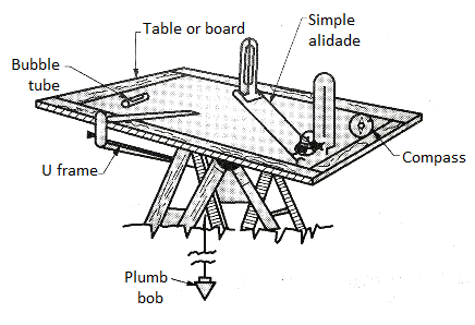
Board: drafting board the drafting board is cautiously fabricated from moist pro wooden in a manner to counteract the impact of warping and damages from weathering. Plane tables are to be had with inside the following distinct sizes.
Tripod: An open body kind mild tripod is typically supplied for solving the drawing desk.
Alidade: aircraft desk surveying device alidade it is a wood or brass ruler of approximately 50-60 cm in length. It is likewise called sight rule. The ‘Object Vane’ and the ‘Sight Vane’ are hinged at its ends.
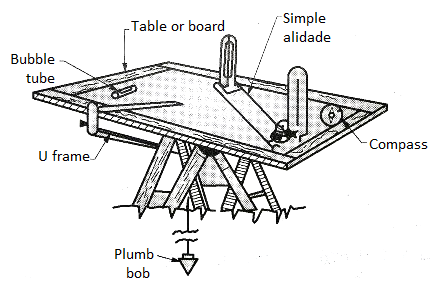
The line of sight accordingly supplied is parallel to the ruling or judicial fringe of the alidade. Where factors too excessive or low are to be sighted, the accuracy and the variety are notably multiplied via way of means of imparting a telescopic alidade.
Telescopic alidade is maximum appropriate for lengthy willing sights.
Trough Compass: aircraft desk surveying device trough compass usually its far 15 cm lengthy and is supplied to devise the magnetic meridian (N-S direction) to facilitate orientation of the aircraft desk with inside the magnetic meridian.
Spirit level: spirit level Plane desk surveying is that the board need to be level. This is typically performed with a round spirit level.
Plumbing Fork: aircraft desk surveying device plumbing fork the use of a plumbing fork is justified best if the size of plotting is huge, the rays being short. However for small-scale mapping that is typically achieved with an aircraft desk surveying the usage of plumbing fork is a sheer waste.
Indian Clinometer: clinometer Since a huge quantity of factors of remark are required to devise contours in aircraft desk surveying, the direct or spirit levelling proves to be very sluggish and accordingly an Indian sample clinometer is employed. This device became made via way of means of J.H Steward.
Q3) Give advantages and disadvantages of plane table surveying?
A3)
Advantages of Plane Table Surveying
- The observations and plotting are achieved simultaneously, subsequently there may be no hazard of omitting important information.
- The mistakes and errors in plotting may be checked via way of means of drawing take a look at lines.
- Irregular items may be plotted as it should be because the lay of land is in view.
- It is maximum fast and beneficial for filling in information.
- No super ability is required.
- Plane desk surveying is much less high priced than theodolite survey.
- It is superb in magnetic regions in which compass survey isn't reliable.
Disadvantages of Plane Table Surveying
- Plane desk surveying isn't appropriate for paintings in a moist weather and in a densely wooded country.
- The absence of measurements (area notes) are inconvenient, if the survey is to be repotted to a few distinct scale.
- It is heavy and awkward to hold and the add-ons are probably to be lost. If does now no longer supply very correct results.
Q4) What is orientation?
A4)
Orientation in aircraft desk surveying is the manner of setting the aircraft desk into a few constant course in order that line representing a sure course at the plan is parallel to that course at the floor.
This is a critical situation to be fulfilled while a couple of device station is to be used. If the orientation isn't always accomplished the desk will now no longer be parallel to itself at exceptional positions ensuing in a standard distortion of the map.
The approaches of centering and orientation are depending on every other. For orientation, the desk will should be turned around approximately its vertical axis, accordingly worrying the centering. There are primary techniques of orientation in aircraft desk surveying.
Orientation with the aid of using thru compass Orientation through lower back sighing.
1. Orientation with the aid of using trough compass
The compass, eleven though much less accurate, frequently proves a precious adjunct in allowing the speedy approximate orientation to be made previous to the very last adjustment. The aircraft desk may be orientated with the aid of using compass below the subsequent situations very last adjustment.
The aircraft desk may be orientated with the aid of using compass below the subsequent situations When pace is extra vital than accuracy When there may be no 2d factor to be had for orientation When the traverse is see you later that gathered mistakes in wearing the azimuth ahead is probably extra than the orientation of the compass For approximate orientation previous to very last adjustment.
2. Orientation with the aid of using back sighting
Orientation in aircraft desk surveying may be accomplished exactly with the aid of using sighting the factors already plotted at the sheet. Two instances may also arise when its miles viable to set the aircraft desk at the factor already plotted at the sheet with the aid of using manner of statement from the preceding phase. When it isn't always viable to set the aircraft desk at the factor.
To orient the desk at the following station, say B, represented at the paper with the aid of using a factor b plotted through line abs drawn from preceding phase A, and the desk is grew to become approximately its vertical axis in any such manner that the road of sight passes thru the floor station A.
While that is achieved, the plotted line abs can be coinciding with the floor line AB (furnished the centering is perfect) and the desk can be orientated. The desk then is clamped with inside the positions.
This approach is equal to that hired in azimuth traversing with the transit. Greater precision is offered than with the compass, however a blunders in course of a line is transferred to succeeding lines.
Q5) What are the methods of plane tabling?
A5)
Methods of aircraft desk surveying: There are especially 4 techniques of aircraft desk surveying, radiation, intersection or triangulation, traversing, and resection.
(1) Radiation approach of aircraft tabling:
In this approach of simple desk survey, the aircraft desk is installation at simplest one station, and diverse factors are positioned through radiating (drawing) a ray from the device station to every of the factors, and plotting to scale alongside the ray the space measured from the station to the factor is sighted.
The radiation approach is appropriate for surveys of small regions that are possibly to be commanded from an unmarried station. It is beneficial in large-scale works if utilized in mixture with different techniques. If the distances are acquired tacheometrically with the assist of telescopic alidade (supplied with stadia-hairs), the paintings may be completed very swiftly and thus, on this case; the approach can have a much wider scope.
(2) Intersection or triangulation approach of aircraft desk surveying:
This approach is broadly hired for plotting the info at the maps. It also can be used for plotting the placement of factors for use at next stations. The diverse factors may be positioned through the intersection of rays drawn from exclusive stations (A and B) forming a baseline. The simplest linear size required is that of the baseline AB at the ground. The approach will also be hired for finding the remote and inaccessible objects, the rivers, in a survey of the hilly regions (in which distances cannot be measured easily), and for checking the faraway objects.
(3) Traversing approach of aircraft desk survey:
Traversing through the aircraft desk is much like compass or theodolite traversing. The approach, therefore, may be used for laying down the survey strains of a closed or unclosed traverse. The info can be plotted with inside the normal manner through taking offsets. The aircraft desk traversing is likewise beneficial for the survey of roads, rivers, etc.
(4) Resection approach of simple desk survey:
The approach of resection is hired for the vicinity of station factors simplest. After setting up the stations, the info are positioned through both radiation and intersection. The essential characteristic of this approach is that the factor plotted at the sheet is the station occupied through the desk. Only one linear size is needed as with inside the intersection approach of aircraft tabling.
Q6) What is two point and three point problems in plane tabling
A6)
Surveying is the artwork of figuring out the relative positions of the factors above, on, or underneath the earth’s floor via way of means of the way of direct or oblique measurements.
And Plane Table surveying is a graphical technique of doing it. In this technique, observations and plotting are carried out simultaneously, which removes recording of the observations and probabilities of lacking out the observations.
In-aircraft desk surveying, units like alidade, Sprit level, Compass, Plumbing fork with a plumb bob, the aircraft desk is used. No optical and automated units are used on this surveying.
Therefore, the aircraft desk surveying is possible for small-scale works wherein an excessive diploma of precision isn't required.
Principle of Plane Table Surveying
Plane desk Surveying works at the precept that each one traces are parallel to the corresponding line at the floor of the aircraft desk is well orientated in role. Here orientation refers back to the procedure of figuring out the location or region of unknown factors with the assist of a recognized factor.
Two-factor Problem A -factor hassle is one of the techniques of resection. Resection is the procedure of figuring out positions of an unknown factor with different recognized factors.
In a -factor hassle, the location of the aircraft desk is decided with recognized factors.
Let us say, P is the factor whose role is to be decided, A&B be the recognized factors and Q be an arbitrary factor. As proven with inside the determine underneath.
While deciding on factor Q the triangles fashioned APQ and BPQ ought to be well-conditioned.
Point Q is kind of orientated, and A and B are plotted in it. Similarly, alidade is sighted to P and call it p1.
Now orient the aircraft desk lower back sighting to Q produces the ray from A to intersect which is known as p.
Also, draw the ray PB to intersect at line bop at b1.
Now, b and b1 factors may not coincide because of the presence of angular blunders in it.
To accurate it, restore the factor R alongside the AB and rotate the desk until the abs line is sighted to R. That is the precise orientation of A and B.
Again, the resect or line a and bob are interested in get role p of factor P.
The following process IS used:
Choose an appropriate auxiliary station D close to C in order that the angles CAD and CBD are neither acute nor obtuse. Set up the aircraft desk at D. Level it. Orient the desk about the use of a magnetic compass of alternatively, be eye-judgment.
Thus the road ab is made about parallel to AB. Clamp the aircraft desk (Fig). Pivot the alidade on a and sight A.
Draw a ray via a. Similarly, pivot the alidade on b and sight B.
Draw a ray via b, intersecting the ray via a at d
1. The factor d1, offers the approximate role of the floor factor D, due to the fact the orientation at D is approximate.
Transfer the factor dl to the floor the use of a plumbing fork and power a peg.
3. With the alidade pivoted at d], sight the station C. Draw a ray d 01 to symbolize the space DC.
Mark the placement of C1 via way of means of estimation. Shift the aircraft desk to C and center it so than the factor 01 is above C. Orient the aircraft desk via way of means of Back-sighting on D.
Thus the orientation at C is similar to it became at D.
Pivot the alidade towards a and sight A. Draw a ray ac2 to intersect the ray dlc1 produced at c2. Thus 02 represents the approximate role of the factor C, due to the fact the orientation continues to be approximate.
The factor b1 offers the approximate role of B with admire to the orientation made at D.
As the duration ab is the genuine illustration of AB, the mistake with inside the orientation is identical to the perspective b1 ab among the strains ab and abl.
To cast off the mistake with inside the orientation, vicinity the alidade alongside abl. Fix ranging rod at a factor Pat far from the aircraft desk and in lien with ab]. Place the alidade alongside ab and flip the aircraft till the ranging rod at P is bisected.
Clamp the aircraft desk. Now the orientation of the aircraft desk is accurate and the lien ab is precisely parallel to AB. To locate the genuine role c of the station C, center the alidade on a and sight A.
Draw a ray ca via a (now no longer shown). Similarly, center the alidade on b and sight B. Draw a ray cb via b.
The intersection of the ray’s ca and cb offers the genuine role of c (now no longer shown).
Unless the factor P is selected pretty a long way off from C, it will become hard to orient the aircraft desk at C correctly.
As the space of P from C is commonly confined because of different considerations, -factor trouble does now no longer deliver correct results.
Q7) What is Telescopic Alidade?
A7)
A telescopic alidade is used whilst it's far required to take inclined attractions.
Also, the accuracy and variety of attractions are extended through its use.
It basically includes a small telescope with a stage tube and graduated arc established on a horizontal axis.
The horizontal axis rests on an A-body geared up with verniers constant in role with inside the equal way as that during a transit.
All the components are subsequently supported on a heavy rule, one aspect of that's used because the operating area alongside which line can be drawn.
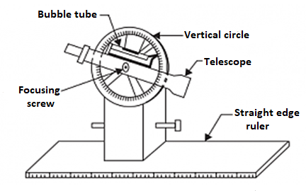
Fig: Telescopic alidade
The inclination of the road of sight may be examine at the vertical circle. The horizontal distance at the personnel stored on the factor.
The elevation of the factor also can be computed through the usage of traditional tachometric relations.
Sometimes, to facilitate calculation work, a Beamon stadia arc can be supplied as an extra.
Thus, the observer can in no time and effortlessly acquire the actual horizontal distance from the aircraft desk to a leveling personnel positioned on the factor and the distinction in elevation among them.
These are the styles of alidade utilized in aircraft desk surveying.
Q8) Explain computation of area and volume
A8)
The predominant goal of the surveying is to compute the regions and volumes. Generally, the lands may be of abnormal formed polygons. There are formulae conveniently to be had for normal polygons like, triangle, rectangle, rectangular and different polygons. But for figuring out the regions of abnormal polygons, one-of-a-kind techniques are used.
Earthwork computation is concerned with inside the excavation of channels, digging of trenches for laying underground pipelines, formation of bunds, earthen embankments, digging farm ponds, land levelling and smoothening. In maximum of the computation the move sectional regions at one-of-a-kind c program language period alongside the period of the channels and embankments are first calculated and the extent of the prismoids are acquired among successive move phase both via way of means of trapezoidal or prismoidal formula.
Calculation of region is finished via way of means of someone of the subsequent techniques:
a) Mid-ordinate method
b) Average ordinate method
c) Trapezoidal rule
d) Simpson’s rule
The mid-ordinate rule
Consider figure.

Let O1, O2, O3, O4……….On= ordinates at equal intervals
l=length of base line
d= common distance between ordinates
h1,h2,……..hn=mid-ordinates

Area = common distance* sum of mid-ordinates
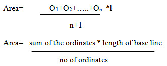
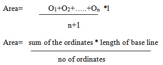
Average ordinate method
Let O1, O2, …..On=ordinates or offsets at regular intervals
l= length of base line
n= number of divisions
n+1= number of ordinates
Q9) Explain the trapezoidal rule
A9)
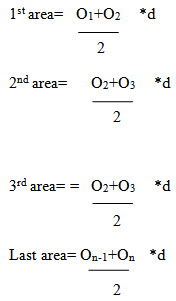
While applying the trapezoidal rule, boundaries between the ends of ordinates are assumed to be straight. Thus the areas enclosed between the base line and the irregular boundary line are considered as trapezoids.
Let O1, O2,On=ordinate at equal intervals, and d= common distance between two ordinates
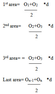
Total area=d/2{O1+2O2+2O3+……. +2On-1+on}

Thus the trapezoidal rule may be stated as follows:
To the sum of the first and last ordinate, twice the sum of intermediate ordinates is added. This total sum is multiplied by the common distance. Half of this product is the required area.
Limitation: There is no limitation for this rule. This rule can be applied for any number of ordinates
Q10) Explain Simpson’s Rule
A10)
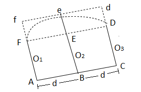
In this rule, the boundaries between the ends of ordinates are assumed to form an arc of parabola. Hence Simpson’s rule is sometimes called as parabolic rule. Refer to figure:
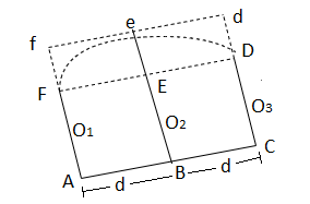
Let
O1, O2, O3= three consecutive ordinates
d= common distance between the ordinates
Area AFeDC= area of trapezium AFDC+ area of segment FeDEF
Here,

Area of segment= 2/3* area of parallelogram FfdD
= 2/3* eE*2d
= 2/3 *{O2- O1+O3 /2}*2d
So, the area between the first two divisions,

= d/3(O1+4O2+O3)
Similarly, the area of next two divisions
∆2 = d/3(O1+4O2+O3) and so on
Total area = d/3[O1+On+4(O2+O4+……) + 2(O3+O5)]

Thus the rule may be stated as the follows
To the sum of the first and the last ordinate, four times the sum of even ordinates and twice the sum of the remaining odd ordinates are added. This total sum is multiplied by the common distance. One third of this product is the required area.
Limitation: This rule is applicable only when the number divisions is even i.e. the number of ordinates is odd.
Q11) Give difference between trapezoidal and Simpsons rule.
A11)
Trapezoidal rule | Simpson’s rule |
1. The boundary between the ordinates is considered to be straight 2. There is no limitation. It can be applied for any number of ordinates 3. It gives an approximate result | The boundary between the ordinates is considered to be an arc of a parabola To apply this rule, the number of ordinates must be odd It gives a more accurate result. |
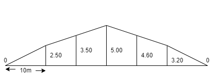
Q12) The following offsets were taken from a chain line to an irregular boundary line at an interval of 10 m:
0, 2.50, 3.50, 5.00, 4.60, 3.20, 0 m
Compute the area between the chain line, the irregular boundary line and the end of offsets by:
a) Mid ordinate rule
b) The average –ordinate rule
c) The trapezoidal rule
d) Simpson’s rule
A12)
(Refer fig)
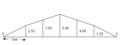
Mid-ordinate rule:
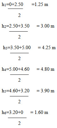
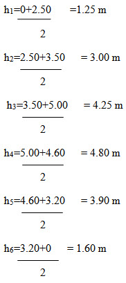
Required area= 10(1.25+3.00+4.25+3.90+1.60)
= 10*18.80=188 m2
By average-ordinate rule:
Here d=10 m and n=6(no of devices)
Base length= 10*6=60 m
Number of ordinates= 7
Required area=10((1.25+3.00+5.00+4.60+3.20+0)/7)

By trapezoidal rule:
Here d=10m
Required area=10/2{0+0+2(2.50+3.50+5.00+4.60+3.20+)}
= 5*37.60=188 m2
By Simpson’s rule:
d=10m
Required area=10/3{0+0+4(2.50+5.00+3.20) +2(3.50+4.60)}
= 10/3{42.80+16.20}=10/3*59.00
10/3*59= 196.66m2
Q13) The following offsets were taken at 15 m intervals from a survey line to an irregular boundary line
3.50, 4.30, 6.75, 5.25, 7.50, 8.80, 7.90, 6.40, 4.40, 3.25 m
Calculate the area enclosed between the survey line, the irregular boundary line, and the offsets, by:
a) The trapezoidal rule
b) Simpson’s rule
A13)

a) The trapezoidal rule
Required area=15/2{3.50+3.25+2(4.30+6.75+5.25+7.50+8.80+7.90+6.40+4.40)}
= 15/2{6.75+102.60} = 820.125 m2
b) Simpson’s rule
If this rule is to be applied, the number of ordinates must be odd. But here the number of ordinates must be odd. But here the number of ordinate is even (ten).
So, Simpson’s rule is applied from O1 to O9 and the area between O9 and O10 is found out by the trapezoidal rule.
A1= 15/3{3.50+4.40+4 ( 4.30+5.25+8.80+6.40)}+2(6.75+7.50+7.90)
= 15/3(7.90+99.00+44.30) = 756.00 m2
A2= 15/2(4.40+3.25) = 57.38 m2
Total area= A1+ A2 =756.00+57.38 = 813.38 m2
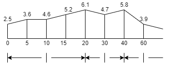
Q14) the following offsets are taken from a survey line to a curves boundary line, and the first and the last offsets by:
a) the trapezoidal rule
b) Simpson’s rule
A14)
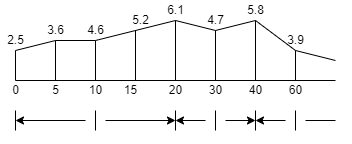
Here the intervals between the offsets are not regular throughout the length.
So, the section is divided into three compartments
Let
∆I= area of the first section
∆II= area of 2nd section
∆III= area of 3rd section
Here
d1= 5 m
d2=10 m
d3=20 m
a) By trapezoidal rule
∆I= 5/2{2.50+6.10+2(3.80+4.60+5.20)} = 89.50 m2
∆II= 10/2{6.10+5.80+2(4.70)} =106.50 m2
∆III= 20/2{5.80+2.20+2(3.90)} = 158.00 m2
Total area = 89.50+106.50+158.00 = 354.00 m2
b) By simpson’s rule
∆I= 5/3{2.50+6.10+4(3.8+5.20) + 2(4.60)} = 89.66 m2
∆II= 10/3{6.10+5.80+4(4.70)} =102.33 m2
∆III= 20/3{5.80+2.20+4(3.90)} = 157.33 m2
Total area= 89.66+102.33+157.33 = 349.32 m2
Unit - 5
Unit - 5
Unit - 5
Plane Table Surveying & Computation of Area & Volume
Q1) What is plane table surveying?
A1)
Plane Table Surveying
Plane Table Surveying
• Plotting of the plan and area observations may be achieved simultaneously
• Geometrical situations of web website online are manuscript with inside the map sheet using aircraft desk and alidade after that topographic information are organized on the map.
• Best outfitted for small-scale surveying
• Surveying commercial regions in which compass survey fails to perform
• Used to fill in information among stations constant via way of means of triangulation approach or theodolite traversing approach.
Plane Table Surveying is one of the maximum fast approach of surveying.
The aircraft desk is a device used for surveying via way of means of a graphical approach wherein the sphere paintings and plotting are achieved simultaneously. The predominant gain of aircraft desk surveying is that the topographic functions to be mapped are in complete view. It is maximum appropriate for small and medium scale-mapping (1:10 thousand to 1:250000).
Q2) Which accessories are used in plane table surveying?
A2)
Accessories Used in Plane Table Surveying
Board: drafting board the drafting board is cautiously fabricated from moist pro wooden in a manner to counteract the impact of warping and damages from weathering. Plane tables are to be had with inside the following distinct sizes.
Tripod: An open body kind mild tripod is typically supplied for solving the drawing desk.
Alidade: aircraft desk surveying device alidade it is a wood or brass ruler of approximately 50-60 cm in length. It is likewise called sight rule. The ‘Object Vane’ and the ‘Sight Vane’ are hinged at its ends.
The line of sight accordingly supplied is parallel to the ruling or judicial fringe of the alidade. Where factors too excessive or low are to be sighted, the accuracy and the variety are notably multiplied via way of means of imparting a telescopic alidade.
Telescopic alidade is maximum appropriate for lengthy willing sights.
Trough Compass: aircraft desk surveying device trough compass usually its far 15 cm lengthy and is supplied to devise the magnetic meridian (N-S direction) to facilitate orientation of the aircraft desk with inside the magnetic meridian.
Spirit level: spirit level Plane desk surveying is that the board need to be level. This is typically performed with a round spirit level.
Plumbing Fork: aircraft desk surveying device plumbing fork the use of a plumbing fork is justified best if the size of plotting is huge, the rays being short. However for small-scale mapping that is typically achieved with an aircraft desk surveying the usage of plumbing fork is a sheer waste.
Indian Clinometer: clinometer Since a huge quantity of factors of remark are required to devise contours in aircraft desk surveying, the direct or spirit levelling proves to be very sluggish and accordingly an Indian sample clinometer is employed. This device became made via way of means of J.H Steward.
Q3) Give advantages and disadvantages of plane table surveying?
A3)
Advantages of Plane Table Surveying
- The observations and plotting are achieved simultaneously, subsequently there may be no hazard of omitting important information.
- The mistakes and errors in plotting may be checked via way of means of drawing take a look at lines.
- Irregular items may be plotted as it should be because the lay of land is in view.
- It is maximum fast and beneficial for filling in information.
- No super ability is required.
- Plane desk surveying is much less high priced than theodolite survey.
- It is superb in magnetic regions in which compass survey isn't reliable.
Disadvantages of Plane Table Surveying
- Plane desk surveying isn't appropriate for paintings in a moist weather and in a densely wooded country.
- The absence of measurements (area notes) are inconvenient, if the survey is to be repotted to a few distinct scale.
- It is heavy and awkward to hold and the add-ons are probably to be lost. If does now no longer supply very correct results.
Q4) What is orientation?
A4)
Orientation in aircraft desk surveying is the manner of setting the aircraft desk into a few constant course in order that line representing a sure course at the plan is parallel to that course at the floor.
This is a critical situation to be fulfilled while a couple of device station is to be used. If the orientation isn't always accomplished the desk will now no longer be parallel to itself at exceptional positions ensuing in a standard distortion of the map.
The approaches of centering and orientation are depending on every other. For orientation, the desk will should be turned around approximately its vertical axis, accordingly worrying the centering. There are primary techniques of orientation in aircraft desk surveying.
Orientation with the aid of using thru compass Orientation through lower back sighing.
1. Orientation with the aid of using trough compass
The compass, eleven though much less accurate, frequently proves a precious adjunct in allowing the speedy approximate orientation to be made previous to the very last adjustment. The aircraft desk may be orientated with the aid of using compass below the subsequent situations very last adjustment.
The aircraft desk may be orientated with the aid of using compass below the subsequent situations When pace is extra vital than accuracy When there may be no 2d factor to be had for orientation When the traverse is see you later that gathered mistakes in wearing the azimuth ahead is probably extra than the orientation of the compass For approximate orientation previous to very last adjustment.
2. Orientation with the aid of using back sighting
Orientation in aircraft desk surveying may be accomplished exactly with the aid of using sighting the factors already plotted at the sheet. Two instances may also arise when its miles viable to set the aircraft desk at the factor already plotted at the sheet with the aid of using manner of statement from the preceding phase. When it isn't always viable to set the aircraft desk at the factor.
To orient the desk at the following station, say B, represented at the paper with the aid of using a factor b plotted through line abs drawn from preceding phase A, and the desk is grew to become approximately its vertical axis in any such manner that the road of sight passes thru the floor station A.
While that is achieved, the plotted line abs can be coinciding with the floor line AB (furnished the centering is perfect) and the desk can be orientated. The desk then is clamped with inside the positions.
This approach is equal to that hired in azimuth traversing with the transit. Greater precision is offered than with the compass, however a blunders in course of a line is transferred to succeeding lines.
Q5) What are the methods of plane tabling?
A5)
Methods of aircraft desk surveying: There are especially 4 techniques of aircraft desk surveying, radiation, intersection or triangulation, traversing, and resection.
(1) Radiation approach of aircraft tabling:
In this approach of simple desk survey, the aircraft desk is installation at simplest one station, and diverse factors are positioned through radiating (drawing) a ray from the device station to every of the factors, and plotting to scale alongside the ray the space measured from the station to the factor is sighted.
The radiation approach is appropriate for surveys of small regions that are possibly to be commanded from an unmarried station. It is beneficial in large-scale works if utilized in mixture with different techniques. If the distances are acquired tacheometrically with the assist of telescopic alidade (supplied with stadia-hairs), the paintings may be completed very swiftly and thus, on this case; the approach can have a much wider scope.
(2) Intersection or triangulation approach of aircraft desk surveying:
This approach is broadly hired for plotting the info at the maps. It also can be used for plotting the placement of factors for use at next stations. The diverse factors may be positioned through the intersection of rays drawn from exclusive stations (A and B) forming a baseline. The simplest linear size required is that of the baseline AB at the ground. The approach will also be hired for finding the remote and inaccessible objects, the rivers, in a survey of the hilly regions (in which distances cannot be measured easily), and for checking the faraway objects.
(3) Traversing approach of aircraft desk survey:
Traversing through the aircraft desk is much like compass or theodolite traversing. The approach, therefore, may be used for laying down the survey strains of a closed or unclosed traverse. The info can be plotted with inside the normal manner through taking offsets. The aircraft desk traversing is likewise beneficial for the survey of roads, rivers, etc.
(4) Resection approach of simple desk survey:
The approach of resection is hired for the vicinity of station factors simplest. After setting up the stations, the info are positioned through both radiation and intersection. The essential characteristic of this approach is that the factor plotted at the sheet is the station occupied through the desk. Only one linear size is needed as with inside the intersection approach of aircraft tabling.
Q6) What is two point and three point problems in plane tabling
A6)
Surveying is the artwork of figuring out the relative positions of the factors above, on, or underneath the earth’s floor via way of means of the way of direct or oblique measurements.
And Plane Table surveying is a graphical technique of doing it. In this technique, observations and plotting are carried out simultaneously, which removes recording of the observations and probabilities of lacking out the observations.
In-aircraft desk surveying, units like alidade, Sprit level, Compass, Plumbing fork with a plumb bob, the aircraft desk is used. No optical and automated units are used on this surveying.
Therefore, the aircraft desk surveying is possible for small-scale works wherein an excessive diploma of precision isn't required.
Principle of Plane Table Surveying
Plane desk Surveying works at the precept that each one traces are parallel to the corresponding line at the floor of the aircraft desk is well orientated in role. Here orientation refers back to the procedure of figuring out the location or region of unknown factors with the assist of a recognized factor.
Two-factor Problem A -factor hassle is one of the techniques of resection. Resection is the procedure of figuring out positions of an unknown factor with different recognized factors.
In a -factor hassle, the location of the aircraft desk is decided with recognized factors.
Let us say, P is the factor whose role is to be decided, A&B be the recognized factors and Q be an arbitrary factor. As proven with inside the determine underneath.
While deciding on factor Q the triangles fashioned APQ and BPQ ought to be well-conditioned.
Point Q is kind of orientated, and A and B are plotted in it. Similarly, alidade is sighted to P and call it p1.
Now orient the aircraft desk lower back sighting to Q produces the ray from A to intersect which is known as p.
Also, draw the ray PB to intersect at line bop at b1.
Now, b and b1 factors may not coincide because of the presence of angular blunders in it.
To accurate it, restore the factor R alongside the AB and rotate the desk until the abs line is sighted to R. That is the precise orientation of A and B.
Again, the resect or line a and bob are interested in get role p of factor P.
The following process IS used:
Choose an appropriate auxiliary station D close to C in order that the angles CAD and CBD are neither acute nor obtuse. Set up the aircraft desk at D. Level it. Orient the desk about the use of a magnetic compass of alternatively, be eye-judgment.
Thus the road ab is made about parallel to AB. Clamp the aircraft desk (Fig). Pivot the alidade on a and sight A.
Draw a ray via a. Similarly, pivot the alidade on b and sight B.
Draw a ray via b, intersecting the ray via a at d
1. The factor d1, offers the approximate role of the floor factor D, due to the fact the orientation at D is approximate.
Transfer the factor dl to the floor the use of a plumbing fork and power a peg.
3. With the alidade pivoted at d], sight the station C. Draw a ray d 01 to symbolize the space DC.
Mark the placement of C1 via way of means of estimation. Shift the aircraft desk to C and center it so than the factor 01 is above C. Orient the aircraft desk via way of means of Back-sighting on D.
Thus the orientation at C is similar to it became at D.
Pivot the alidade towards a and sight A. Draw a ray ac2 to intersect the ray dlc1 produced at c2. Thus 02 represents the approximate role of the factor C, due to the fact the orientation continues to be approximate.
The factor b1 offers the approximate role of B with admire to the orientation made at D.
As the duration ab is the genuine illustration of AB, the mistake with inside the orientation is identical to the perspective b1 ab among the strains ab and abl.
To cast off the mistake with inside the orientation, vicinity the alidade alongside abl. Fix ranging rod at a factor Pat far from the aircraft desk and in lien with ab]. Place the alidade alongside ab and flip the aircraft till the ranging rod at P is bisected.
Clamp the aircraft desk. Now the orientation of the aircraft desk is accurate and the lien ab is precisely parallel to AB. To locate the genuine role c of the station C, center the alidade on a and sight A.
Draw a ray ca via a (now no longer shown). Similarly, center the alidade on b and sight B. Draw a ray cb via b.
The intersection of the ray’s ca and cb offers the genuine role of c (now no longer shown).
Unless the factor P is selected pretty a long way off from C, it will become hard to orient the aircraft desk at C correctly.
As the space of P from C is commonly confined because of different considerations, -factor trouble does now no longer deliver correct results.
Q7) What is Telescopic Alidade?
A7)
A telescopic alidade is used whilst it's far required to take inclined attractions.
Also, the accuracy and variety of attractions are extended through its use.
It basically includes a small telescope with a stage tube and graduated arc established on a horizontal axis.
The horizontal axis rests on an A-body geared up with verniers constant in role with inside the equal way as that during a transit.
All the components are subsequently supported on a heavy rule, one aspect of that's used because the operating area alongside which line can be drawn.
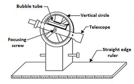
Fig: Telescopic alidade
The inclination of the road of sight may be examine at the vertical circle. The horizontal distance at the personnel stored on the factor.
The elevation of the factor also can be computed through the usage of traditional tachometric relations.
Sometimes, to facilitate calculation work, a Beamon stadia arc can be supplied as an extra.
Thus, the observer can in no time and effortlessly acquire the actual horizontal distance from the aircraft desk to a leveling personnel positioned on the factor and the distinction in elevation among them.
These are the styles of alidade utilized in aircraft desk surveying.
Q8) Explain computation of area and volume
A8)
The predominant goal of the surveying is to compute the regions and volumes. Generally, the lands may be of abnormal formed polygons. There are formulae conveniently to be had for normal polygons like, triangle, rectangle, rectangular and different polygons. But for figuring out the regions of abnormal polygons, one-of-a-kind techniques are used.
Earthwork computation is concerned with inside the excavation of channels, digging of trenches for laying underground pipelines, formation of bunds, earthen embankments, digging farm ponds, land levelling and smoothening. In maximum of the computation the move sectional regions at one-of-a-kind c program language period alongside the period of the channels and embankments are first calculated and the extent of the prismoids are acquired among successive move phase both via way of means of trapezoidal or prismoidal formula.
Calculation of region is finished via way of means of someone of the subsequent techniques:
a) Mid-ordinate method
b) Average ordinate method
c) Trapezoidal rule
d) Simpson’s rule
The mid-ordinate rule
Consider figure.

Let O1, O2, O3, O4……….On= ordinates at equal intervals
l=length of base line
d= common distance between ordinates
h1,h2,……..hn=mid-ordinates

Area = common distance* sum of mid-ordinates
Average ordinate method
Let O1, O2, …..On=ordinates or offsets at regular intervals
l= length of base line
n= number of divisions
n+1= number of ordinates
Q9) Explain the trapezoidal rule
A9)
While applying the trapezoidal rule, boundaries between the ends of ordinates are assumed to be straight. Thus the areas enclosed between the base line and the irregular boundary line are considered as trapezoids.
Let O1, O2,On=ordinate at equal intervals, and d= common distance between two ordinates
Total area=d/2{O1+2O2+2O3+……. +2On-1+on}

Thus the trapezoidal rule may be stated as follows:
To the sum of the first and last ordinate, twice the sum of intermediate ordinates is added. This total sum is multiplied by the common distance. Half of this product is the required area.
Limitation: There is no limitation for this rule. This rule can be applied for any number of ordinates
Q10) Explain Simpson’s Rule
A10)
In this rule, the boundaries between the ends of ordinates are assumed to form an arc of parabola. Hence Simpson’s rule is sometimes called as parabolic rule. Refer to figure:
Let
O1, O2, O3= three consecutive ordinates
d= common distance between the ordinates
Area AFeDC= area of trapezium AFDC+ area of segment FeDEF
Here,

Area of segment= 2/3* area of parallelogram FfdD
= 2/3* eE*2d
= 2/3 *{O2- O1+O3 /2}*2d
So, the area between the first two divisions,

= d/3(O1+4O2+O3)
Similarly, the area of next two divisions
∆2 = d/3(O1+4O2+O3) and so on
Total area = d/3[O1+On+4(O2+O4+……) + 2(O3+O5)]

Thus the rule may be stated as the follows
To the sum of the first and the last ordinate, four times the sum of even ordinates and twice the sum of the remaining odd ordinates are added. This total sum is multiplied by the common distance. One third of this product is the required area.
Limitation: This rule is applicable only when the number divisions is even i.e. the number of ordinates is odd.
Q11) Give difference between trapezoidal and Simpsons rule.
A11)
Trapezoidal rule | Simpson’s rule |
1. The boundary between the ordinates is considered to be straight 2. There is no limitation. It can be applied for any number of ordinates 3. It gives an approximate result | The boundary between the ordinates is considered to be an arc of a parabola To apply this rule, the number of ordinates must be odd It gives a more accurate result. |
Q12) The following offsets were taken from a chain line to an irregular boundary line at an interval of 10 m:
0, 2.50, 3.50, 5.00, 4.60, 3.20, 0 m
Compute the area between the chain line, the irregular boundary line and the end of offsets by:
a) Mid ordinate rule
b) The average –ordinate rule
c) The trapezoidal rule
d) Simpson’s rule
A12)
(Refer fig)
Mid-ordinate rule:
Required area= 10(1.25+3.00+4.25+3.90+1.60)
= 10*18.80=188 m2
By average-ordinate rule:
Here d=10 m and n=6(no of devices)
Base length= 10*6=60 m
Number of ordinates= 7
Required area=10((1.25+3.00+5.00+4.60+3.20+0)/7)

By trapezoidal rule:
Here d=10m
Required area=10/2{0+0+2(2.50+3.50+5.00+4.60+3.20+)}
= 5*37.60=188 m2
By Simpson’s rule:
d=10m
Required area=10/3{0+0+4(2.50+5.00+3.20) +2(3.50+4.60)}
= 10/3{42.80+16.20}=10/3*59.00
10/3*59= 196.66m2
Q13) The following offsets were taken at 15 m intervals from a survey line to an irregular boundary line
3.50, 4.30, 6.75, 5.25, 7.50, 8.80, 7.90, 6.40, 4.40, 3.25 m
Calculate the area enclosed between the survey line, the irregular boundary line, and the offsets, by:
a) The trapezoidal rule
b) Simpson’s rule
A13)

a) The trapezoidal rule
Required area=15/2{3.50+3.25+2(4.30+6.75+5.25+7.50+8.80+7.90+6.40+4.40)}
= 15/2{6.75+102.60} = 820.125 m2
b) Simpson’s rule
If this rule is to be applied, the number of ordinates must be odd. But here the number of ordinates must be odd. But here the number of ordinate is even (ten).
So, Simpson’s rule is applied from O1 to O9 and the area between O9 and O10 is found out by the trapezoidal rule.
A1= 15/3{3.50+4.40+4 ( 4.30+5.25+8.80+6.40)}+2(6.75+7.50+7.90)
= 15/3(7.90+99.00+44.30) = 756.00 m2
A2= 15/2(4.40+3.25) = 57.38 m2
Total area= A1+ A2 =756.00+57.38 = 813.38 m2
Q14) the following offsets are taken from a survey line to a curves boundary line, and the first and the last offsets by:
a) the trapezoidal rule
b) Simpson’s rule
A14)
Here the intervals between the offsets are not regular throughout the length.
So, the section is divided into three compartments
Let
∆I= area of the first section
∆II= area of 2nd section
∆III= area of 3rd section
Here
d1= 5 m
d2=10 m
d3=20 m
a) By trapezoidal rule
∆I= 5/2{2.50+6.10+2(3.80+4.60+5.20)} = 89.50 m2
∆II= 10/2{6.10+5.80+2(4.70)} =106.50 m2
∆III= 20/2{5.80+2.20+2(3.90)} = 158.00 m2
Total area = 89.50+106.50+158.00 = 354.00 m2
b) By simpson’s rule
∆I= 5/3{2.50+6.10+4(3.8+5.20) + 2(4.60)} = 89.66 m2
∆II= 10/3{6.10+5.80+4(4.70)} =102.33 m2
∆III= 20/3{5.80+2.20+4(3.90)} = 157.33 m2
Total area= 89.66+102.33+157.33 = 349.32 m2