Unit 5
Synchronous machines
Q1) Explain Armature reaction in brief?
A1)
1. The effect of Armature (stator) flux on the flux produced by the rotor field poles is called Armature Reaction.
2. When the current flows through the armature winding of an alternator, a flux is produced by the resulting MMF.
3. This armature flux reacts with the main pole flux, causing the resultant flux to become either less than or more than the original main field flux.
For simplicity, we consider a 3 phase, 2 pole alternator shown in the figure below.
4. The winding of each pole is assumed to be concentrated, but the effects of armature reaction will be the same as if a distributed winding were also used. The armature reaction in synchronous machine affects the main field flux and vary differently for different power factors.
5. Here armature reaction is discussed for following three conditions, namely unity power factor, zero power factor lagging and zero power factor leading.
6. The power factor can be defined as the cosine of the angle between the armature phase current and the induced EMF in the armature conductor in that phase.
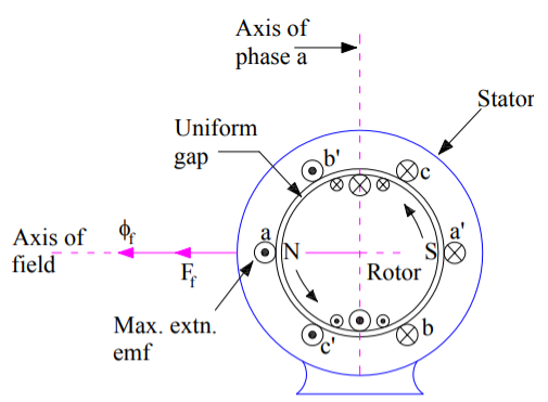
Fig : 3 phase 2 pole alternator
Q2) State and derive equation Synchronous impedance?
A2)
1. The actual generated voltage consists of the summation of two component voltages. One of these components voltages is the voltage that would be generated if there were no armature reaction.
2. It is the voltage that would be generated because of only field excitation. This component of the generated voltage is called the excitation voltage, Eexc.
3. The other component of the generated voltage is called armature reaction voltage, EAR.
4. This is the voltage that must be added to the excitation voltage to take care of the effect of armature reaction upon the generated voltage.

5. Since armature reaction results, in a voltage effect in circuit caused bu change in flux by current in the same circuit, its effect is of the nature of an inductive reactance .therefore EAR is equivalent to a voltage of inductive reactance and

6. The inductive Reactance XAR is a fictitious reactance which will result in a voltage in armature circuit to account for the effect of armature reaction upon the voltage relations of the armature circuit.
7. Therefore armature reaction voltage can be modelled as in inductor in series with internal generated voltage.
8. In additional to the effect of armature reaction, the stator winding also has a self-inductance and resistance.
Let La = self-inductance of stator winding.
Xa = self-reactance of stator winding.
Ra = armature (stator) resistance.
The terminal voltage V is given by

Where
RaIa = armature resistance drop
Xa Ia = armature leakage reactance drop
XAR Ia = armature reaction voltage
9. The armature reaction effect and the leakage flux effect in the machine are both represented by inductive reactance . Therefore, it is customary to combine them into a single reactance, is called the synchronous reactance of the machine, Xs.
 …… (4)
 …..(5)


The impedance Zs is called synchronous impedance.
10. The synchronous Reactance Xs is the fictitious reactance employed to account for voltage effects in the armature circuit produced by the actual armature leakage reactance and by the change in air gap flux caused by the armature reaction.
11. Similarly, synchronous impedance Zs is a fictitious impedance employed to account for voltage effects in the armature circuit produced by the actual armature resistance, the actual armature leakage reactance, and the change in air gap flux produced by armature reaction
Q3) State and explain the methods for Determination of Voltage Regulation?
A3) The following methods are used to determine the voltage regulation of smooth cylindrical rotor type alternators.
A. Direct Load test
B. Indirect methods
A. Direct Load test:
1. The alternator is run at synchronous speed and its terminal voltage is adjusted to its rated value V. The load is varied until the ammeter and wattmeter indicate the rated values at the given power factor.
2. Then the load is removed and the speed and field excitation are kept constant. The open circuit and no load voltage Ea is recorded.
3. The voltage regulation found from percentage voltage regulation. The method of direct loading is suitable only from small alternators of power rating less than kVA.
B. Indirect methods:
For Large alternators, the three indirect methods which are used to predetermine the voltage regulation smooth cylindrical type alternators are as following.
1. Synchronous impedance method or EMF method
2. Ampere turn method or EMF method
3. Zero power factor method or Potier method
Q4) Explain Phasor diagram of a Characteristics of Synchronous Motor?
A4)
1. The phasor diagram of a Characteristics of Synchronous Motor is shown in fig . The theory of these motors has been developed on the basis of synchronous reactance, which takes care of leakage reactance and armature reaction.
2. A salient pole machine, which has a non-uniform air gap, is described by direct and quadrature axis reactance’s.
3. Variation of the armature current of the motor when its excitation is varied is described by V-curves when the motor develops a given power.
The variation of excitation brings about the following:
- Change in armature current
- Change in line power factor
- Slight change in the load angle.
However, there are minimum and maximum excitations for a given power developed.
4. An increase in the mechanical load at constant excitation would tend to retard the rotor.
5. The angle by which the rotor tends to fall behind the no-load position is called the load angle. In the process of attaining a final position the rotor undergoes oscillations which are damped by damper windings.
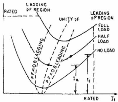
Fig : V curve graph
Q5) State and explain with diagram V- curves?
A5)
1. V curve is a plot of the stator current versus field current for different constant loads. The Graph plotted between the armatures current Ia and field current If at no load the curve is obtained known as V Curve.
2. Since the shape of these curves is similar to the letter “V”, thus they are called V curve of synchronous motor.
3. The power factor of the synchronous motor can be controlled by varying the field current If.
4. As we know that the armature current Ia changes with the change in the field current If.
5. Let us assume that the motor is running at NO load. If the field current is increased from this small value, the armature current Ia decreases until the armature current becomes minimum.
6. At this minimum point, the motor is operating at unity power factor. The motor operates at lagging power factor until it reaches up to this point of operation.
7. If now, the field current is increased further, the armature current increases and the motor start operating as a leading power factor. The graph drawn between armature current and field current is known as V curve. If this procedure is repeated for various increased loads, a family of curves is obtained.
The V curves of a synchronous motor are shown below.

Fig : V curves of synchronous motor
8. The point at which the unity power factor occurs is at the point where the armature current is minimum.
9. The curve connecting the lowest points of all the V curves for various power levels is called the Unity Power Factor Compounding Curve. The compounding curves for 0.8 power factor lagging and 0.8 power factor leading are shown in the figure above by a red dotted line.
10. The loci of constant power factor points on the V curves are called Compounding Curves. It shows the manner in which the field current should be varied in order to maintain constant power factor under changing load.
11. Points on the right and left of the unity power factor corresponds to the over excitation and leading current and under excitation and lagging current respectively.
12. The V curves are useful in adjusting the field current. Increasing the field current If beyond the level for minimum armature current results in leading power factor.
13. Similarly decreasing the field current below the minimum armature current result results in lagging power factor. It is seen that the field current for unity power factor at full load is more than the field current for unity power factor at no load.
Q6) State and explain two reaction theory of salient pole machine?
A6)
1. The theory proposes to resolve the given armature MMFs into two mutually perpendicular components, with one located along the axis of the rotor of the salient pole. It is known as the direct axis or d axis component.
2. The other component is located perpendicular to the axis of the rotor salient pole. It is known as the quadrature axis or q axis component.
3. The d axis component of the armature MMF Fa is denoted by Fd and the q axis component by Fq. The component Fd is either magnetizing or demagnetizing.
4. The component Fq results in a cross-magnetizing effect. If Ψ is the angle between the armature current Ia and the excitation voltage Ef and Fa is the amplitude of the armature MMF, then


- Salient Pole Synchronous Machine Two Reaction Theory:
1. In the cylindrical rotor synchronous machine, the air gap is uniform. The pole structure of the rotor of a salient pole machine makes the air gap highly non-uniform.
2. Consider a 2 pole, salient pole rotor rotating in the anticlockwise direction within a 2 pole stator as shown in the figure below.
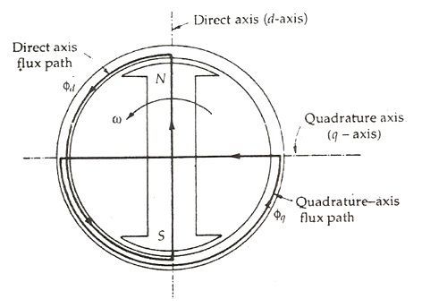
Fig : salient pole rotor rotating anticlockwise in 2 pole stator
3. The axis along the axis of the rotor is called the direct or the d axis. The axis perpendicular to d axis is known as the quadrature or q axis.
4. The direct axis flux path involves two small air gaps and is the path of the minimum reluctance. The path shown in the above figure by ϕq has two large air gaps and is the path of the maximum reluctance.
The rotor flux BR is shown vertically upwards as shown in the figure below.
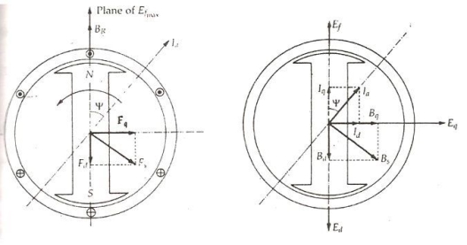
Fig : flux showing diagram( upwards )
5. The rotor flux induces a voltage Ef in the stator. The stator armature current Ia will flow through the synchronous motor when a lagging power factor load is connected it.
6. This stator armature current Ia lags behind the generated voltage Ef by an angle Ψ.
7. The armature current produces stator magneto motive force Fs. This MMF lags behind Ia by angle 90 degrees. The MMF FS produces stator magnetic field BS long the direction of Fs.
8. The stator MMF is resolved into two components, namely the direct axis component Fd and the quadrature axis component Fq.
Unit - 3
Flow Through Open Channel
Q1) Write a short note on flow through open channel.
A1)
FLOW THROUGH OPEN CHANNEL:
This unfastened floor of the liquid is subjected to atmospheric stress. Hence, open channel float also can be described because the float of liquid thru a passage at atmospheric stress. The float in an open channel takes vicinity because of gravity this is finished with the aid of using imparting a mattress slope. Open-channel float, a department of hydraulics and fluid mechanics, is a form of liquid float inside a conduit or in channel with a unfastened floor, referred to as a channel.
The different form of float inside a conduit is pipe float. These forms of float are comparable in lots of methods however vary in a single crucial appreciate: the unfastened floor. Open-channel float has a unfastened floor, while pipe float does now no longer.
The evaluation of float styles of water floor shape, pace, shear pressure and discharge thru a circulate attain falls below the heading Open Channel Flow. Open Channel Flow is described as fluid float with an unfastened floor open to the atmosphere. Examples encompass streams, rivers and culverts now no longer flowing full.
Open channel float assumes that the stress on the floor is consistent and the hydraulic grade line is on the floor of the fluid Steady and unsteady float rely on whether or not float intensity and pace alternate with time at a point. In standard if the amount of water getting into and leaving the attain does now no longer alternate, then the float is taken into consideration steady.
Steady float in a channel may be both Uniform and Non-uniform (various).When the common velocities in successive pass sections of a channel are the same, the float is uniform. This happens simplest whilst the pass phase is consistent. Non-uniform float consequences from slow or surprising modifications with inside the pass sectional area.
Uniform float and sundry float describe the modifications intensive and pace with appreciate to distance. If the water floor is parallel to the channel backside float is uniform and the water floor is at regular intensity. Varied float or non-uniform float happens whilst intensity or pace alternate over a distance, like in a constriction or over a riffle. Gradually various float happens whilst the alternate is small, and unexpectedly various float happens whilst the alternate is large, as an example a wave, waterfall, or the speedy transition from a circulate channel into the inlet of a culvert.
Q2) Explain types of channel in detail.
A2)
GENERAL: Types of channel and their geometrical properties
Open channel may be stated to be because the deep whole floor having typically the pinnacle floor open to ecosystem. Open channel glide may be stated to be because the glide of fluid (water) over the deep hole floor (channel) with the duvet of ecosystem at the pinnacle. Examples of open channels glide are river, streams, flumes, sewers, ditches and lakes etc. we may be stated to be as open channel is a manner for glide of fluid having stress identical to the atmospheric stress.
While alternatively glide below stress is stated to be as pipe glide e.g. Glide of fluid via the sewer pipes. Open-channel glide is typically classified on the premise of steadiness. Flow is stated to be regular whilst the rate at any factor of commentary does now no longer extrude with time; if it modifications from time to time, glide is stated to be unsteady.
At each instant, if the rate is the identical in any respect factors alongside the channel, glide is stated to be uniform; if it isn't the identical, glide is stated to be non-uniform.
Non-uniform glide which is likewise regular is referred to as as various glide; non-uniform glide that's unsteady is referred to as as variable glide. Flow takes place from a better to a decrease awareness via way of means of useful resource of gravity.
Q3) Explain types of open channel Open Channels
A3)
Types of open channel
Open Channels are categorized as:
Rigid boundary open channels
Rigid boundary open channels may be stated to be because the open channels with the non-changeable boundaries. While however if open channel has the limits which adjustments because of scouring movement or deposition of sediments, such channels are stated to be as free boundary open channels.
Loose boundary open channels
While however if open channel has the limits which adjustments because of scouring movement or deposition of sediments, such channels are stated to be as free boundary open channels. The open channels wherein shape, length of pass phase and slope of the mattress stay regular are stated to be because the prismatic channels.
Prismatic open channels
If the pass-phase of a channel is uniform in the course of its period and the lowest slope is regular, it's far referred to as Prismatic Channels. Key Features. Uniform channel pass-phase in the course of the period. Constant backside slope. Prismatic channels may be triangular, rectangular, parabolic, trapezoidal or circular.
Rigid boundary open channels may be stated to be because the open channels with the non-changeable boundaries. While alternatively if open channel has the limits which modifications because of scouring motion or deposition of sediments, such channels are stated to be as free boundary open channels. The open channels wherein shape, length of move segment and slope of the mattress stay regular are stated to be because the prismatic channels.
Open channels glide is tough to research than the pipe glide. That's why in open channel glide size empirical method is adopted. The speed of glide in open channel may be computed via way of means of assist of Manning's formula:
V = 1/n x R0.sixty six x S0.5
In pipe glide the conduit (pipe for motion of fluid) typically absolutely fills with water for the improvement of pipe stress, at the same time as with inside the conduit that's partly stuffed may have open channel glide. There isn't any any restrict for the conduit in case of open channel glide to be absolutely stuffed.
Q4) Explain types of flow in open channel.
A4)
Types of flow in open channel.
The float of liquid via a channel with an unfastened floor is described as open channel float.
The float in an open channel takes region because of gravity this is performed with the aid of using supplying a mattress slope.
1. Steady and Unsteady Flow
In an open channel float, if the float parameters consisting of intensity of float, the rate of float and the price of float at a specific factor at the fluid do now no longer extrude with appreciate to time, then it's far referred to as consistent If v is the rate of the fluid, Q is the price of float and d is the intensity of float, then for a consistent float:
Dv/dt = 0; dQ/dt = 0; dy/dt = 0;
And is at any factor at the open channel float, the float parameters like intensity of float, the rate of float and price of float do extrude their cost with appreciate to time, then it's far referred to as an unsteady float.
2. Uniform Flow and Non-Uniform Flow
The float with inside the channel is stated to be uniform, if, for a given duration of the channel, the rate of float, the intensity of float stays consistent. i.e. dy/dS = 0 ; dv/dS=0; In a Non-uniform float, the float parameters like velocity, intensity of float, and so on do now no longer stay consistent for a given duration of the channel. Dy/dS and dv/dS now no longer same to zero The Non-uniform float may be once more described as Rapidly various float (R.V.F) and Gradually Varied Flow (G.V.F). In the case of R.V.F, the intensity of float unexpectedly modifications over a smaller duration of the channel. It rises up all at once for a quick duration and settles back.
While in a G.V.F, the intensity of float modifications steadily over an extended duration of the channel.
3. Laminar Flow and Turbulent Flow
Laminar and turbulent float in open channel float is described primarily based totally at the Reynolds Number, re. The Reynolds wide variety is given with the aid of using the relation: Reynolds’s wide variety FOR Laminar Flow and Turbulent Flow If the Reynolds wide variety Re is much less than 500 or 600, then the float is referred to as laminar float.
4. Critical, Sub-Critical and Super - Critical Flow
The open channel float is classified as important or sub-important or excellent-important primarily based totally at the Froude wide variety Fe. Froude wide variety is given with the aid of using the relation: Froude Number for Sub, excellent and critical float in Open Channel Open channel float is Sub-important if the Froude wide variety is much less than
Q5) What do you mean by uniform flow?
A5)
UNIFORM FLOW
If you are taking any quantity detail of the waft, the houses of the waft at every factor in that quantity might be identical. This may be very strict, and a piece unreal. There are diverse approaches to specific that uniformity, as an example in case you outline streamlines in keeping with a few simple assumptions then the ones streamlines might be directly and parallel.
Notice that that is a geometric definition, it's miles approximately comparative values, and says not anything approximately absolutely the values in easy fluid mechanics which continue to be unfastened to alternate in different impartial dimensions, ie over time. Pipe waft as an example is in no way truely uniform due to the fact the fluid interacts with the pipe itself, however could have a fairly uniform profile in case you recollect a small waft section, excessive velocity, and occasional viscosity, etc.
Chezy’s and Manning’s equations
1. Chezy’s Formula
French engineer Antoine Chezy derived Chezy’s formula in the 1760s to study the flow behavior. The formula is given by:
V = C. R ½ S ½ (Eq.1)
Where C= Chezy’s constant; R= hydraulic radius;
S= slope of the channel bottom
The Chezy’s constant is determined using any of the following equations:
1. Bazin’s Formula
K = Bazin’s constant and depends on the roughness of the surface of the channel; m is the hydraulic mean depth or hydraulic radius.
 2. Ganguillet-Kutter Formula
N= Roughness coefficient called as Kutter’s constant, whose value varies for different surfaces
I = slope of the bed; m = hydraulic mean depth (also represented as R)
Chezy’s coefficient is depending on the flow’s nature and the character of the channel surface. The willpower of Chezy’s coefficient is much less correct and now no longer normally used because of the shortage of statistics to discover equal roughness without enough experimental and area data. Therefore, its miles used handiest for clean boundaries.
2. Manning’s Formula
Irish engineer Robert Manning derived manning’s formula in 1889. It is derived from Chezy's formula.
Manning derived an average empirical relation for Chezy’s coefficient as:
C = 1/nR⅙ ;
Hence, the final formula (Eq.1) becomes,
V = [(1/n)R ⅙ ] R½ S½
Which gives the average velocity of flow as,
V = (1/n) R ⅔ S½ (Eq.2)
V= velocity of flow
n= Manning’s Roughness coefficient
R= Hydraulic radius/hydraulic depth
S= bed slope or slope of the channel bottom
Manning’s roughness coefficient is determined by
1. Strickler equation
n = [(D50) ⅙ ] / 24 or K ⅙ /24
K = Roughness Height
D50 = 50% of the particles are finer than the size 50 ( bed particles)
2. Meyer Formula
N = [(D90) ⅙ ]/26
D50 = 90% of the particles are finer than the size 90 ( bed particles)
Meyer formula is used when the channel bed contains a higher percentage of coarse-grained particles.
Q6) Explain hydraulically most efficient rectangular, triangular and trapezoidal sections
A6)
Hydraulically most efficient rectangular, triangular and trapezoidal sections
The nice hydraulic phase of an open channel is characterized through provision of most discharge with a given pass sectional location. In fact, the selection of nice hydraulic phase additionally possesses different blessings than hydraulic performance.
For instance, for a given discharge fee the usage of nice hydraulic phase may want to assure the least pass sectional location of the channels. Substantial financial savings might be crafted from the discount in the quantity of excavation and from the usage of much less channel linings.
To gain the nice hydraulic channel phase, a few variables need to be determined. For a waft equation, e.g. Manning, the channel phase carries variables (square and triangular sections) or 3 variables (trapezoidal and round-backside triangular sections). For a given waft, the nice hydraulic channel phase may be received through minimizing the wetted perimeter (or the pass-sectional location). Any waft equation, e.g. Manning, may be used.
In this paper, Manning equation may be used to get the nice hydraulic phase for a trapezoidal phase for open channels with special aspect slopes.
- A channel is stated to be maximum inexpensive if It offers most discharge for a given cross -sectional location and mattress shape, It has minimal wetted perimeter, and It entails lesser excavation for the designed quantity of discharge. The following factors are really well worth noting:
- The maximum inexpensive phase of a square channel is one that has hydraulic radius identical to 1/2 of the intensity of flow.
- The maximum inexpensive phase of a trapezoidal channel is one that has hydraulic suggest intensity identical to 1/2 of the intensity of flow.
- The maximum inexpensive phase of a triangular channel is one that has its sloping facets at a perspective of forty five diploma with the vertical.
- The discharge thru a channel of square phase is most whilst its breadth is two times the intensity.
- The discharge thru a channel of trapezoidal phase is most whilst the sloping facet is identical to 1/2 of the width on the top.
- The discharge thru a channel of round phase is most whilst the intensity of water is identical to 0.95 instances the diameter of the round channel.
- The pace thru a channel of round phase is most whilst the intensity of water is identical to 0.81 instances the diameter of round channel.
- A section is said to be most efficient, if, for a given cross-section area, the discharge carrying capacity is maximum.
- The highest component of total construction cost is of lining & if the perimeter is kept minimum the cost of lining will be minimum, hence it will be the most economical section.
- There are some important section and condition to be most efficient;
Section | Condition |
Rectangular | R = y/2 |
Triangular | θ = 45o |
Trapezoidal |
|
Computations of normal depth of flow
The Froude Number and Critical Open Channel Flow
The Froude range is of hobby right here due to the fact its cost for any specific open channel waft presents facts on whether or not that waft is subcritical, important or supercritical waft. The Froude range is described as follows:
Fr = V/(gL)1/2,
In which Fr is the Froude Number V is the common speed of the liquid with inside the channel (toes/sec for U.S. Gadgets or m/s for S.I.). g is the acceleration because of gravity (32.17 toes/sec2 for U.S. Gadgets or 9.eighty one m/s2 for S.I.). L is a feature duration for the specific sort of open channel (toes for U.S. Gadgets or m for S.I.) For example, with waft in a square channel, the feature duration, L, is the intensity of waft, y, making
Fr = V/(gy)1/2 .
For waft in a non-square channel, Fr = V/[g(A/B)]1/2, due to the fact the feature duration, L, is A/B, in which A is the cross-sectional region of liquid waft, and B is the floor width.
For information on calculating cross-sectional region, floor width and hydraulic radius for numerous channel shapes, see the article, “Calculation of Hydraulic Radius for Open Channel waft.” As cited above, the cost of the Froude range offers facts approximately the sort of waft. Details are summarized below: If Fr> 1, then it's far supercritical waft If Fr< 1, then it's far subcritical waft If Fr = 1, then it's far important waft
Q7) Explain conveyance of channel in detail.
A7)
Conveyance of channel
The general method that consists on figuring out watercourses wherein preservation works can also additionally have a capacity to definitely preserve or boom conveyance ability and watercourses wherein the attribution of region or receptors reaping rewards is essential. Chapter three makes a specialty of how the influences of conveyance are quantified and Chapter four describes the estimation of the advantages of such preservation works.
The choice of the pleasant control alternative is provided in Chapter five and Chapter 6 discusses the results. The method provided is aimed to offer a countrywide evaluate of the in all likelihood conveyance control works required to offer a specific degree of advantages even though it is referred to that nearby particularities can't be taken into consideration via way of means of the method.
The desired control alternative and its advantages described at every watercourse at a countrywide scale represent the baseline state of affairs against which the actual Environment Agency preservation programmers in UK may be as compared and assessed.
This is performed figuring out watercourses wherein preservation works can also additionally have a capacity to definitely preserve or boom conveyance ability (capacity essential maintained watercourses) and watercourses wherein the attribution of advantages is essential (capacity essential benefitting watercourses).
Assembling collectively the statistics of the capacity essential maintained and benefitting watercourses produces a photo of the strategic lengths of watercourse to be maintained.
For example, preservation works can also additionally have a totally positive effect in a single specific watercourse, lowering effectively water stages and growing conveyance ability, but without editing the flood hazard of adjoining properties and thus, now no longer generating any benefit.
Q8) Write a note on section factor for uniform flow.
A8)
Section factor for uniform flow
The excellent hydraulic channel segment is decided with the aid of using the usage of Lagrange's technique of undetermined multipliers. For a given go with the drift, roughness coefficient, and longitudinal slope, this technique optimizes the channel segment with the aid of using minimizing the wetted perimeter (or the cross‐sectional region) situation to a constraint.
Any go with the drift equation, e.g. Manning, may be used because the constraint. The channel segment ought to incorporate any wide variety of variables; e.g., variables (square and triangular sections), 3 variables (trapezoidal and round‐backside triangular sections) and so forth.
It is proven that minimization of the wetted perimeter and minimization of the cross‐sectional region are mathematically equivalent. The technique is implemented to the same old sections in addition to the round‐backside triangular segment. The excellent hydraulic round‐backside triangular segment, the willpower of that's made feasible with the aid of using this method, is barely greater green than the same and greater broadly used trapezoidal segment.
The geometric homes of the excellent hydraulic round‐backside triangular segment are of first-rate interest. Its intensity is identical to the round‐backside radius and is two times its hydraulic radius.
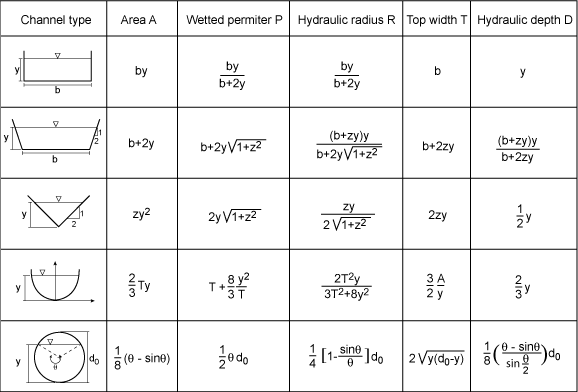
Q9) What is normal slope and normal discharge?
A9)
Normal slope and normal discharge
The pinnacle row indicates a hypothetical discharge time collection on the upstream boundary, which may be utilized in each approaches. The factor in time for the subsequent rows is indicated with the aid of using the dashed vertical line. In the uniform discharge method, the cutting-edge discharge cost of the time collection defines the release for all reaches of the simulated gadget on the cutting-edge factor in time (2d row left). In contrast, for the kinematic wave method, the temporal variability of discharge is contemplated in a spatial variability as well (2d row right).
For the kinematic wave method, float intensity may additionally range because of the spatial variant of discharge (0.33 row right). In instances of uphill channel slopes with inside the downstream direction, the uniform discharge method will reproduce the results of ponding (fourth row left), at the same time as the kinematic wave method can't cope with such situations (fourth row right) Vaginal discharge comes from glands internal your vagina and cervix. These glands produce small quantities of fluid additionally called vaginal secretions. The fluid flows out of the vagina every day, cleaning vintage cells which have covered the vagina. This is a very herbal process—it’s your body’s manner of maintaining your vagina healthful and clean.
Discharge varies from lady to lady. Some girls have discharge each day, at the same time as others revel in it much less frequently. Normal vaginal discharge is normally clean or milky and might have a diffused heady fragrance that isn't always unsightly or foul smelling. It’s additionally crucial to realize that vaginal discharge adjustments over the path of a lady’s menstrual cycle. These adjustments in color and thickness are related to ovulation and are herbal. But out of doors of regular adjustments related to your cycle, different adjustments might not be regular. Your discharge may also imply an imbalance of healthful microorganism to your vagina, which may be a signal that everyone isn't always well.
Finding the normal depth in an open channel can be accomplished by using Manning’s equation. Manning’s equation relates the flow rate in the channel (discharge, Q) to the cross- sectional area (A), the hydraulic radius (R), the slope of the channel (So), and the channel roughness (N).
Q = 1.49/N AR2/3 So1/2 Eq.1
Where: Q – Channel Discharge (Cfs)
A – Channel Area(Ft2)
R – Hydraulic Radius (Ft)
So – Longitudinal Channel Slope (Ft/Ft)
N – Manning’s Roughness Value (see Figure 3)
P – Wetted Perimeter (ft)
Eq.1 can be turned into a root-solving problem and solved using root-solving techniques such as the Bisection Method, Newton-Raphson Method, etc. Depending upon how the problem is rewritten, you may introduce unwanted sensitivity problems. Use Eq. 2 for your root-solving problem to minimize numerical sensitivity problems.
0 = AR2/3 – QN/1.49 So1/2 …………….Eq. 2
Trapezoidal Channel
Consider the trapezoidal channel shown in Figure 1 below. Note the bottom width of the channel (B) and the channel side-slopes (Z : 1). The channel side-slope is not to be confused with the longitudinal slope of the channel (So). If the bottom width of the channel and the side slopes of the channel are known, then the cross-sectional area of flow and the wetted perimeter can be easily calculated using the equations below. If the left and right side slopes are identical, Eq. 4 can be used; however, if the side
Q10) Explain conveyance of channel.
A10)
Conveyance of channel
The general method that consists on figuring out watercourses wherein preservation works can also additionally have a capacity to definitely preserve or boom conveyance ability and watercourses wherein the attribution of region or receptors reaping rewards is essential. Chapter three makes a specialty of how the influences of conveyance are quantified and Chapter four describes the estimation of the advantages of such preservation works.
The choice of the pleasant control alternative is provided in Chapter five and Chapter 6 discusses the results. The method provided is aimed to offer a countrywide evaluate of the in all likelihood conveyance control works required to offer a specific degree of advantages even though it is referred to that nearby particularities can't be taken into consideration via way of means of the method.
The desired control alternative and its advantages described at every watercourse at a countrywide scale represent the baseline state of affairs against which the actual Environment Agency preservation programmers in UK may be as compared and assessed.
This is performed figuring out watercourses wherein preservation works can also additionally have a capacity to definitely preserve or boom conveyance ability (capacity essential maintained watercourses) and watercourses wherein the attribution of advantages is essential (capacity essential benefitting watercourses).
Assembling collectively the statistics of the capacity essential maintained and benefitting watercourses produces a photo of the strategic lengths of watercourse to be maintained.
For example, preservation works can also additionally have a totally positive effect in a single specific watercourse, lowering effectively water stages and growing conveyance ability, but without editing the flood hazard of adjoining properties and thus, now no longer generating any benefit.
Q11) What do you mean by critical flow?
A11)
CRITICAL FLOW
Critical glide takes place while the glide pace in a channel equals the wave pace generated with the aid of using a disturbance or obstruction. In this situation the Froude number (Fr) = 1. When the wave pace exceeds the glide pace (Fr is much less than 1) waves can glide upstream, water can pond in the back of an obstruction, and the glide is stated to be subcritical or tranquil. When Fr is more than 1 waves cannot be generated upstream and the glide is stated to be supercritical, rapid, or shooting.
In nature, supercritical glide is located most effective in rapids and waterfalls, however it's miles frequently created artificially with the aid of using weirs and flumes with the goal of measuring discharge. Critical, or choked, glide isn't always most effective an thrilling instructional trouble however is likewise essential in lots of sensible applications, which includes in electricity technology and in chemical method industries wherein, without a particular understanding of vital glide conduct, protection or overall performance of a device can be compromised.
Experimental statistics can be to be had for a particular utility however reliance frequently needs to be positioned upon theoretical models, which, in turn, should be demonstrated towards nicely-certified statistics. Single-segment choking is nicely understood [see, for example, Roy (1988)] however, with the advent of a segment change, the conduct of fluid turns into some distance extra complex [for a detailed review of two-phase critical flow models and data, see Elias and Lellouche (1994)].
The incidence of choking in a device is conventionally described because the most mass glide fee as a feature of downstream pressure. To illustrate this, remember Figure 1, wherein a big reservoir is attached with the aid of using a glide route of arbitrary geometry to any other reservoir whose thermodynamic kingdom may be managed precisely.
Q12) Explain specific energy and its diagram.
A12)
Specific energy and its diagram
Specific electricity or massif electricity is electricity according to unit mass. It is likewise every so often known as gravimetric electricity density, or simply electricity density eleven though electricity density extra exactly way electricity according to unit volume. It is used to quantify, for example, saved warmness and different thermodynamic residences of materials including precise inner electricity, precise enthalpy, precise Gibbs loose electricity, and precise Helmholtz loose electricity. It will also be used for the kinetic electricity or capacity electricity of a body.
Specific electricity is an in depth property, while electricity and mass are sizeable residences. The SI unit for precise electricity is the joule according to kilogram (J/kg). Other devices nevertheless in use in a few contexts are the kilocalorie according to gram (Cal/g or kcal/g), in general in food-associated topics, watt hours according to kilogram with inside the subject of batteries, and the Imperial unit BTU according to pound (Btu/lb), in a few engineering and carried out technical
The idea of precise electricity is associated with however wonderful from the chemical belief of molar electricity, this is electricity according to mole of a substance, which makes use of devices of electricity according to mole, including J/mol, kJ/mol, or the older (however nevertheless extensively used) kcal/mol. Specific electricity is electricity according to unit mass. (It is likewise every so often known as "electricity density," eleven though "electricity density" extra exactly way electricity according to unit volume.) It is used to quantify, for example, saved warmness or different thermodynamic residences of materials
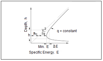
Alternate depths & Computations of critical depth:
In open channel go with the drift, unique strength (e) is the strength length, or head, relative to the channel bottom. Specific strength is expressed in phrases of kinetic strength, and ability strength, and inner strength. The Bernoulli equation, which originates from a manipulate quantity analysis, is used to explain unique strength relationships in fluid dynamics.
The shape of Bernoulli’s equation mentioned right here assumes the go with the drift is incompressible and steady. The 3 strength additives in Bernoulli's equation are elevation, stress and velocity. However, due to the fact that with open channel go with the drift, the water floor is open to the atmosphere, the stress time period among factors has the equal fee and is consequently ignored.
Thus, if the unique strength and the rate of the go with the drift with inside the channel are known, the intensity of go with the drift may be determined. This courting may be used to calculate modifications intensive upstream or downstream of modifications with inside the channel along with steps, constrictions, or manipulate structures.
It is a plot between the specific energy on abscissa (x – axis) and depth of flow on ordinate (y- axis).
- Consider a rectangular channel having bed width ‘B’ and depth of flow y.
E = y + V2/2g = y + Q2/2gA2
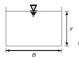
E = y + Q2/2g A2
E = y + Q2/2gB2y2 …….(1)
If y 0, E
y , E y
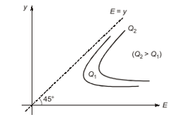
- The curve obtained is valid for one particular discharge as discharge increases the curve shifts to the right.
- The curve would be different for different cross- section however its nature would be same.
From equation (1)
E = y + Q2/2g. B2y2
If the datum coincides with the channel mattress on the cross-phase, the ensuing expression is understand as unique electricity and is denoted via way of means of E.
It can be mentioned that while the entire electricity in a actual fluid glide continually decreases with inside the downstream direction, the unique electricity is consistent for a uniform glide and might both lower or growth in a various glide, for the reason that elevation of the mattress of the channel relative to the elevation of the electricity line, determines the unique electricity.
Q13) Explain section factor for critical flow.
A13)
Section factor for critical flow
Section factor for critical flow
The section factor for critical flow computation (Z) is the product of the water area and the square root of the hydraulic depth.
Z = A A/T = A D Z2 = A2D D = Z2/A2
For critical flow V2/2g = D/2, by substituting
V2/2g = D/2 = z2/2A2 Z2 = V2A2/g Z = VA/g Z = Q/g
Therefore Qc = Zc g …………………(3.1)
Where Qc represent the discharge that would make the depth y critical and known as the critical discharge. When the energy coefficient is not assumed to be unity
Qc = Zcg/α
Eq. (3.1 and 3.2) are very useful tool for the computation and analysis of critical flow in open channel, when the discharge is give the equations will give the critical section factor (Zc). And hence the critical Depth yc. Section factor (Z) for different channel –section shape is give as
Rectangular: Z = by1.5 Triangular : Z = 2/2 my2.5 Trapezoidal: Z = 
To simplify the computation of critical flow, dimensionless curves showing the relation between the depth and the section factor Z have been prepared for different type of channels sections. These self-explanatory curves will help to determine the depth y for a given section factor Z and vice versa.
Critical slope:
Vital waft Critical waft takes place while the waft pace in a channel equals the wave pace generated with the aid of using a disturbance or obstruction. In this circumstance the Froude number (Fr) = 1. When the wave pace exceeds the waft pace (Fr is much less than 1) waves can waft upstream, water can pond at the back of an obstruction, and the waft is stated to be subcritical or tranquil. When Fr is extra than 1 waves can't be generated upstream and the waft is stated to be supercritical, rapid, or shooting.
In this circumstance a status wave is shaped over obstructions with inside the river bed. In nature, supercritical waft is observed most effective in rapids and waterfalls, however it's far regularly created artificially with the aid of using weirs and flumes with the intention of measuring discharge.
Vital waft the waft that takes place while the waft pace in a river channel equals the wave pace generated with the aid of using a disturbance or obstruction. When the wave pace exceeds the waft pace (i.e. Fr is much less than 1) waves can waft upstream, water can pond at the back of an obstruction, and the waft is stated to be subcritical or tranquil. Created artificially with the aid of using weirs and flumes, with the intention of measuring discharge.
Q14) What is specific force?
A14)
Specific force and its diagram
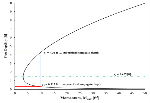
Specific pressure is described because the non-gravitational pressure in step with unit mass. Specific pressure (additionally known as g-pressure and mass-particular pressure) is measured in meters/second² (m·s−2) that's the devices for acceleration. Thus, particular pressure isn't always in reality a pressure, however a form of acceleration. However, the (mass-) particular pressure isn't always a coordinate-acceleration, however as an alternative a right acceleration, that's the acceleration relative to loose-fall.
Forces, particular forces, and right accelerations are the identical in all reference frames, however coordinate accelerations are frame-dependent. For loose bodies, the particular pressure is the purpose of, and a degree of, the body's right acceleration.
The g-pressure acceleration is similar to the particular pressure. The acceleration of an item loose falling toward the earth relies upon at the reference frame (it disappears with inside the loose-fall frame, additionally known as the inertial frame), however any g-pressure "acceleration" can be found in all frames. This particular pressure is 0 for freely-falling objects, in view that gravity performing on my own does now no longer produce g-forces or particular forces.
Accelerometers at the floor of the Earth degree a regular 9.eight m/s^2 even if they're now no longer accelerating (this is, after they do now no longer go through coordinate acceleration).
This is due to the fact accelerometers degree the right acceleration produced through the g-pressure exerted through the ground (gravity performing on my own in no way produces g-pressure or particular pressure). Accelerometers degree particular pressure (right acceleration), that's the acceleration relative to loose-fall, now no longer the "standard" acceleration this is relative to a coordinate system.
Q15) Explain condition for critical flow in detail.
A15)
Conditions of critical flow
Critical go with the drift happens while the go with the drift speed in a channel equals the wave speed generated through a disturbance or obstruction. In this situation the Froude number (Fr) = 1.
When the wave speed exceeds the go with the drift speed (Fr is much less than 1) waves can go with the drift upstream, water can pond in the back of an obstruction, and the go with the drift is stated to be subcritical or tranquil. When Fr is more than 1 waves can't be generated upstream and the go with the drift is stated to be supercritical, rapid, or shooting.
In nature, supercritical go with the drift is discovered best in rapids and waterfalls, however it's far frequently created artificially through weirs and flumes with the goal of measuring discharge
The water surface profile is a measure of how the flow depth changes longitudinally. The profiles are classified based on the relationship between the actual water depth (y), the normal depth (yn) and the critical depth (yc). Normal depth is the depth of flow that would occur if the flow was uniform and steady, and is usually predicted using the Manning's Equation. Critical depth is defined as the depth of flow where energy is at a minimum for a particular discharge.
Flow profiles are classified by the slope of the channel (So), yn, and yc. There are five slope classifications designated by the letters C, M , S, A, and H (critical, mild, steep, adverse, and horizontal) respectively.
- Mild (M) if yn >yc
- Steep (S) if yn <yc
- Critical (C) if yn= yc
- Adverse (A) if So < 0 (if slope is positive in the downstream direction)
- Horizontal (H) if So = 0
The profile is further classified according to the relative position of the actual flow depth to normal and critical depth as designated by the numbers 1, 2, and 3.
- Type 1 curve: Actual depth is greater than yc and yn, flow is subcritical
- Type 2 curve: actual depth is between yc and yn, flow can be either subcritical or supercritical
- Type 3 curve: actual depth is less than both yc and yn, flow is supercritical.