Unit - 3
Design of simple and built up beams
Q1) What is Design of simple and built up beams?
A1)
Design of simple
Beams are structural elements subjected to transverse loads in the plane of bending causing bending moments and shear forces.
Symmetrical b sections about z-z axis (major axis) are economical and geometrical properties of such sections are available in SP (6).
The compression flange of the beams can be laterally supported (restrained) or laterally unsupported (unrestrained) depending upon whether restraints are provided or not.
The beams are designed for maximum BM and checked for maximum SF, local effects such as vertical buckling and crippling of webs and deflection. Section 8 (IS 800-2007) shall be followed in the design of such bending members.
Types of Sections
Beams can be different cross sections depending on the span and loadings.
1. Simple I section
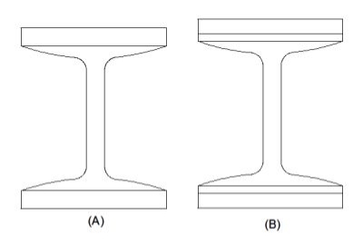
2. I section with cover plate
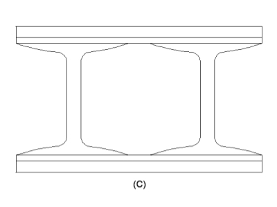
3. Two I section with cover plate
4. Built-up I section
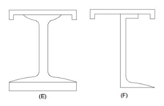
5. Gantry girder
6. Box sections
7. Castled beams
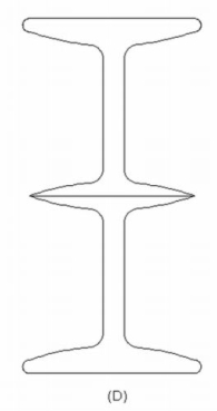
8. Two I placed one above the other
1) Simple I section: Use of simple I section is normal span and loading
2) I section with cover plate: Use of I section with cover plate is heavy load and larger span
3) Two I section with cover plate: it is use of very heavy load with large span
4) Built-up I section: it is used to plate girder where span exceed 20 m and loads are heavy.
5) Gantry girder: Gantry girder is use for movable heavy loads, lift loads etc.
6) Box sections: It is use for service lines
7) Castled beams: It is use for light loads and large span
8) Two I placed one above the other: It is used for light loading with large span
Behaviour of Beam in Flexure
In order to expect the flexural behavior of any brittle fabric like concrete, load deflection technique on 3 factors become essential. The 3 factor technique is the manner to compute the deflections because of implemented masses so as to investigate the flexural behavior.
RCC beam are efficiently used as structural participants in diverse constructions. RCC is a homogeneous material which is having diverse properties.
RCC beams are classified as under strengthened, balanced and over strengthened sections on the evaluation basis. In RCC each concrete and steels will reaches the pressure and corresponding lines because of outside subjected hundreds concurrently.
When in an RCC beam, if the metallic has a tendency to fail earlier than the pressure in concrete reaches the maximum permissible pressure such beams are known as under strengthened sections. If each concrete and metallic reaches the permissible pressure values concurrently such beams are taken into consideration as balanced sections. If the concrete has a tendency to fail earlier than the pressure in metallic reaches the maximum permissible pressure such beams are taken into consideration as over strengthened sections. In the following article primarily based totally on the laboratory experimental evaluation the flexure behavior of diverse sections are discovered through damaging methods.
DESIGN CRITERIA
The primary layout criterion for any form of shape is safety, serviceability and economy. Due to these primary esteem properties of RCC elements, they are abundantly used in all structural applications. For the structural use of RCC elements it must obey the following parameters. The shape must be secure and economical that it can perfectly resist both tension and compressive stress. The shape must be stiff and look like unblemished such that it ought to be resisted the bending moments and shear forces because of outside applied masses.
The shape must be economical by means of it can be able to resist all type of stress and availability of substances to make RCC. In order to are expecting the secure and monetary situations of RCC it's far essential to evaluate the situations of remaining masses and corresponding deflections below precise constrains.
To attain the applicable outcomes one had to behavior an experimental analysis. When an RCC beam is subjected to a few outside loadings the beam tends to bend with a few deflection due to loading. At any point in the cross section of the beam is considered the pressure distribution can be such that everyone the fibers above the impartial axis by skip thru the CG are in compression, while all of the fibers beneath the impartial axis are in tension.

Built up beams
A built-up beam is likewise referred to as compound beam.
The built-up beams are used whilst the span, load and corresponding bending second are of such magnitudes that rolled metal beam segment will become insufficient to offer required segment modulus.
Built-up beams also are used whilst rolled metal beams are insufficient for restricted intensity.
In constructing construction, the intensity of beam is restricted with the aid of using an area furnished with the aid of using the architect.
Drawing beam of small intensity do now no longer offer required segment modulus. Therefore, plates are connected to the beams.
The energy of rolled metal beams is multiplied with the aid of using including plates to its flange that's one of the techniques forming built-in segment.
The different technique is to compound some of rolled metal sections themselves.
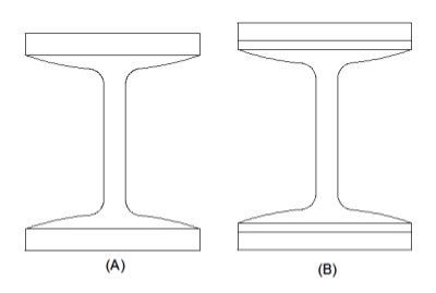
The built-up sections shown in figure’ A’ and ‘B’ are used for heavy loads and small spans.
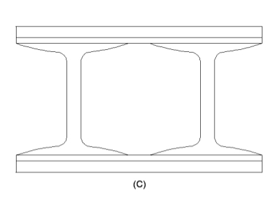
The built-up section ‘C’ is also used for heavy loads and small span.
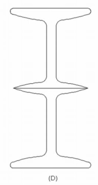
The built-up section ‘D’ is used for light loads and large spans.
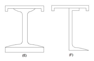
The built-up sections ‘E’ & ‘F’ are provided for Gantry girders.
Design Procedure of the Built-up Beams design
Here are the simple steps that are to be followed for the design of Built-up Beams.
Step one
- The effective span and load required to be carried by the built-up beam are known.
- Maximum bending moment and shear force in built-up beams are calculated.
Step two
- Value of yield stress (fy) for structural steel is to be assumed.
- The permissible bending stress (sigma bc) is calculated.
Step three
- The required section modulus (Z) for the given beam section is calculated.
Step four
- From the steel table, a trial section for a beam is adopted having the modulus of section (Z) about 25% to 50% in excess of that requirement. The geometrical proportion of beam sections are noted.
Step five
- When the depth of the beam is noted, then the usually the practice is to select from ISI handbook No.1 (Steel tables).
- The strongest Rolled steel beam that will allow for necessary thickness of power plates at top and bottom.
Step six
- The area of power plate required is found out by trial-and-error method are by;
I = Ibeam + 2(Ap)(h/2) (h/2)
- For finding the area, divide the whole equation by h/2.
Step seven
- Width of cover plate and thickness are decided with the restriction of outstands.
Step Eight
- Check for bending stress/Actual bending compressive stress
(Sigma bc) calculated = (maximum bending moment/Gross MI) x Distance of extreme fibre in compression from Neutral Axis
= (M/Ixx) x y1
- Actual bending tension stress
sigma bt, cal = (sigma bc) cal x (gross area of tension flange/Net area of tension flange)
= Value should not exceed the permissible bending stress (sigma bc) or (sigma bt) = 0/66fy
Step nine
- Check for shear and Deflection
Q2) Explain Laterally restrained Beam?
A2)
Laterally Restrained Beams
Beams subjected to BM develop compressive and tensile forces and the flange subjected to compressive forces has the tendency to deflect laterally. This out of plane bending is called lateral bending or buckling of beams. The lateral bending of beams depends on the effective span between the restraints, minimum moment of inertia (Iyy) and its presence reduces the plastic moment capacity of the section.
Beams where lateral buckling of the compression flange are prevented are called laterally restrained beams. Such continuous lateral supports are provided in two ways:
i) The compression flange is connected to an RC slab throughout by shear connectors.
Ii) External lateral supports are provided at closer intervals to the compression flange so that it is as good continuous lateral support. Cl 8.2.1 (pg - 52 and 53) gives the specifications in this regard.
Design of such laterally supported beams are carried out using Clauses 8.2.1.2, 8.2.1.3, 8.2.1.5, 8.4, 8.4.1, 8.4.1.1, 8.4.2.1 and 5.6.1 (Deflection) In addition, the beams shall be checked for vertical buckling of web and web crippling. The design is simple, but lengthy and does not involve trial and error procedure.
Design steps:
- Calculate the factored load and the maximum bending moment and shear force
- Obtain the plastic section modulus required
Zp = (M*Vmo /Fy)
a suitable section for the beam-ISLB, ISMB, ISWB or suitable built-up sections (doubly symmetric only). (Doubly symmetric, singly symmetric and asymmetric- procedures are different)
3. Check for section classification such as plastic, compact, semi-compact or slender. Most of the sections are either plastic or compact. Flange and web criteria.

4. Calculate the design shear for the web and is given by

5. Calculate the design bending moment or moment resisted by the section (for plastic and compact)

6. Check for buckling
7. Check for crippling or bearing
8. Check for deflection
Q3) Explain un-restrained beam?
A3)
Laterally Unrestrained Beams
Beams subjected to BM develop compressive and tensile forces and the flange subjected to compressive forces has the tendency to deflect laterally. This out of plane bending is called lateral bending or buckling of beams. Lateral buckling of beams involves three kinds of deformations namely lateral bending, twisting and warping. The lateral bending of beams depends on the effective span between the restraints, minimum moment of inertia (Iyy) and can reduce the plastic moment capacity of the section.
The value of Mer can be calculated using the equations given in cl. 8.2.2.1 pg-54 for doubly symmetric c/s and annex E (pg 128-129) for c/s symmetrical about the minor axis. The design bending compressive strength can be calculated using a set of equations as specified.
Design steps:
1) Maximum shear force

Maximum bending force

2) Selecting of section
Assuming fbd = 130 N/mm^2

Properties:
Bf , tf , tw
Rmin
Zp
3) Classification of cross section
Flange

Web

Section is plastic or semi plastic
4) Design shear strength


Strength in bending Md need not be reduced due to shear
5) Design bending strength

6) Check Deflection limit

Q4) A simply supported beam of effective span 4 m carries a factored point load of 350 kN at mid span. The section is laterally supported throughout the span. Design the cross section using I section.
A4)
- Maximum shear force
V= reaction = W/2 = 1575 kN
2. maximum bending moment
M= WL/4= 350 kn-m
3. selection of cross section (using yielding criteria)
Zp required = 

Select an ISLB 500@75kg/m (using annex H Is 800-2007)
Sectional properties d=500 mm, Izz= 38549 x 1064 mm^4
Zp= 1773.7x 10^3 mm^3 > Zp required
Ze= 1545.2 X 10^3 mm^3
4. classification of section


5. Design shear strength


6. Design bending strength


7. Checks
- Web buckling

At a concentrated load W


Buckling class C
From table IS 800-2007 and fy= 250 Mpa
Kl/r | Fcd |
130 | 74.3 |
131.78 | ? |
140 | 66.2 |
Interpolation
Fcd= 72.85 N/mm^2
At concentrated point load


At reaction R


B. Web crippling


C. Deflection limits
Working load = 350/1.5 = 233.33Kn


Provide an ISLB 500@ 75 kg/m beam
Q5) What is Curtailment of flange plates?
A5)
In beam B.M is very less near to the simple support therefore, no need to provide same size of flange plate. To achieve economy flange thickness are curtailed near to the support called curtailment of flange.
Its position from support is calculating by equating the B.M at that section to the design bending strength at the section.
As the bending moment decreases towards the supports, some of the flange plates may be curtailed. There is not much difference in the effective depth after curtailment and will nearly equal to 'D', the depth over angles.
1- Curtailment of plates for a girder carrying uniformly distributed load-
Moment of resistance varies as effective flange area - i.e. area of flange A, 'plus 1/8 area of web (=Af+ Aw/d) d Let Ln be the theoretical length of the plate which is to be curtailed.
a = net area of plate to be curtailed plus the net area of plates above this as taken in full section.
A1 = total effective flange area. B.M. Diagram will be a parabola
M= k A1
Mn=K(A1-A)
M/(M-Mn) =L2/Ln2


2- Accurate method of curtailment-
In this method, the moment or resistance of the section after removing the plate is calculated and the point at which the B.M. Will be equal to this moment of resistance, will be the theoretical point at which the plate may be cut-off.

If M is the maximum B.M. And Mn is the moment of resistance of the section after removing the plate and Ln is the length of plate
M/(M-Mn) =L2/Ln2
Q6) Explain Design of welded plate girder?
A6)
Welded Plate Girders
Beams of long span subjected to heavy loads are encountered in buildings and bridges. For these beams, ready-made I sections are not suitable since their depth is limited due to buckling of the web. In this situation, girders are to be fabricated using flange and web plates as per requirement. Usually, the flange and web plates are connected by welding (Figure). Girders fabricated in this manner are known as welded plate girders and their depth to web thickness ratio (d/tw) may be up to 400. Because of higher d/tw, the buckling of the web becomes the major problem with these girders. To overcome this problem, different types of stiffeners are provided as shown in Figure
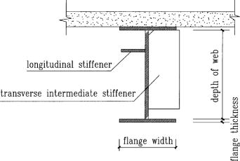
A welded plate girder is more efficient section as the whole area is effective in resisting loads. The flange plate is welded directly to the web and no flange angles are used. The flange plate is welded directly to the web and no flange angles are used. The box girders may also be fabricated by using two or more webs. It is uneconomical to use a number of thin cover plates as flanges one thick plate may be used as a flange and where it is desired to decrease the flange area, a thinner plate may be used. The thinner and thicker plates may then be butt welded. The self-weight in kg may be taken as – WL/400, where W is the total superimposed load in kg and 1 is the span in metres.
Types of Plate Girders
There may be exclusive classifications relying at the requirements used or relying on the character of the manufacturing of the girders.
There varieties of plate girders.
1. Reverted Plate Girder
2. Welded Plate Girder
Reverted Plate Girder
It is an aggregate of flanges, internet, and different vital stiffness. There are related via way of means of a mechanical method, revert, and plates aren't welded collectively.
- Generally, 90% of the shear is carried via way of means of the internet.
- Connection of the internet and the flange is stabilized via way of means of the angel sections reverted to the flange. Reverts want to be designed for the horizontal shear.
- The reverts that make the relationship among the internet and flange angles want to be designed for horizontal shear and vertical hundreds that carried out to the flange after they switch to the internet.
- Angle sections are used as internet stiffness in revert girders.
Application of Plate Girders
Plate girders are broadly used as assisting systems in exclusive regions. The following regions may be highlighted as key regions of use.
Bridge production
Plate girders are specifically utilized in railway and avenue bridges. Mostly the antique railway bridges may be highlighted as plate girder bridges.
In addition, field girder bridges, beam bridges, navy girder composite bridges, and half – thru plate girder bridges are taken into consideration because it uses.
- Ships
- Gantry beams
- Oil and fuel line platforms
- Load testing
- Cranes
- Lifting systems
Advantages of Plate Girder
- They may be used to hold heavy hundreds
- Speed production
- Grater balance
- High resistance to fatigue failures
- Easy to assemble while as compared with truss kind bridges
- Easy for maintenance
Disadvantages of Plate Girder
- They cannot be used to assist big spans
- Less architectural appearance
- A bit tough to deal within the course of the placement
- Production will be finished strictly according with the layout.
The articles have been written on Steel Beam Design as according to BS 5950 and Steel Beam Design Worked Example [Universal Beam] could be referred for extra facts on metal beam designs.
Further facts on metal beams may be studied from the article Types of metal beams.
Welded plate girders are maximum broadly utilized in production because of the convenience of manufacturing and its miles a far extra green sort of girder.
These sections are specifically utilized in bridge production. The plate girder bridge could be very stiff and it is able to retain very excessive hundred seven as resisting the lateral movements. This movement may be found within side the railway bridges. Further, they may be used to increase the field kind girders.
There are empirical or approximation strategies to decide the general peak of the plate girder and thickness of the flange and internet.
Components of welded Plate Girders
Mainly there are 5additives in a girder. The meeting of that 5-thing is the entire girder. The basic requirement is to make an “I” girder having very excessive bending and shear stiffens similarly to the alternative nearby buckling resistances.
- Web Plate
- Flange
- Stiffeners (bearing, longitudinal, and intermediate)
- Splices for flange and internet
- End Connection
Web Plate
The vertical plate of the girder is called the internet plate.
Its thickness is primarily based totally at the layout necessities and the peak can also be determined primarily based totally at the web page condition and as according to the hundreds carried out at the internet.
The internet typically includes the carried-out hundreds at the flange as shear forces. The impact of the internet isn't always usually taken into consideration while the layout for the bending.
The internet is at risk of buckling while thinner and better boom while the hundreds are carried out. Therefore, exclusive varieties of stiffness so as to be discussing on this article, are welded to the internet have its electricity.
Flange
There isn't any distinctiveness aside from using a separate plate for the flange. The flange plate could be welded or related via way of means of different method as mentioned beneath Neath exclusive varieties of plate girders.
Not like rolled sections, we connect the internet and the flange collectively to shape the plate girder.
The flange is layout to hold the bending movement and stiffener or extra plate are furnished as according to the layout necessities.
Stiffeners
Stiffeners are furnished to enhance structural potential heading off the nearby buckling failures. In addition, they may be used to hold the hundreds carried out to the beam till it allotted into the beam.
The following varieties of stiffeners can be found in those varieties of metal elements.
- Bearing stiffeners
- Longitudinal stiffeners
- Intermediate stiffeners
The bearing stiffeners are furnished at assist to distribute the assist response to the internet with none buckling failures. There are jacking stiffness except the bearing stiffeners for installations functions as indicated within side the following figure.
Steel plates welded within side the longitudinal and the transverse instructions also are used to reinforce the internet.
The vertical or the transverse stiffeners may be typically found in maximum of the metal beams that deliver heavy hundreds.
Splices for Flange and Web
It is the splice connection of the internet and the flange of the girder.
When the duration of the girder is less than the span, we must have a splice connection.
This is a second and shear shifting joint which gives beam continuation.
End Connection
End connection is the maximum tough a part of the structural detailing of a metal beam.
When there is continuation or if we are assisting the girder to a few assists, the relationship desires to be designed accordingly.
However, maximum of the time, plate girders are saved as definitely supported on the stop assist. In such situations, we must offer the stiffeners on the stop connection.
A comparable lay out system is followed while designing the endplates and the stiffener furnished vertically connecting the internet and the flange.
Q7) Explain Design of cross section?
A7)
1. Self weight of plate girder
The following imperical formula may be used to access the self weight of the beam

Where,
W= Total factored load
w = Factored self weight
2. Economical depth
Assuming that the moment M is carried out by flange only the economical depth d of girder may be found as given below


Where bf and tf are width and thickness of the flange

Taking

Then

For

(Differentiate area A w.r.t d and equated to zero)


In selecting value of k=d/tw the following codal provision will be useful
1) If 
2) Minimum web thickness based on serviceability requirement – cl. 8.6.1.1 ( IS 800-2000)
- When transverse stiffeners are not provided

b. When transverse stiffeners are provided
- When


2. When 

3. When 

4. When c>3d the web shall be considered unsiffned
c. When transverse stiffeners and longitudinal stiffeners at one level only are provided (0.2d from compression flange)
- When


2. When 

3. When 

d. When a second longitudinal stiffeners (located at neutral axis is provided)

3) Minimum web thickness based on compression flange buckling requirement (cl.8.6.1.2)
To avoid buckling of compression flnge into the web the ewb thickness shall satisfy the following
- When transverse stiffeners are not provided


2. When transverse stiffeners are provided an
- When


2. When 

3. Size of flanges
Assuming moment of resisted by flange only and using material safety factore for a plastic section
(Af.fy.d)/1.1 = M
Hence area of flange Af may be found. ( IS 800-2000)
Q8) A simply supported welded plate girder of an effective span of 24 m subjected to uniformly distributed load of 35 kn/m throughout the span excluding the self weight of plate girder assume compression flange laterally supported throughout the span and yield stress of steel is 250 MPa Design cross section of plate girder stiffeners.
A8)
1) Maximum bending moment and shear force
- Self weight of plate girder
Factored load = 35x 1.5 = 52.5 kN/m
Self weight of plate girder
W1= W/200 = 6.3 kN/m
Total uniformly distributed load on plate girder
w = 58.8 KN/m
b. Maximum bending moment
M= 58.8 x 24^2 /8 = 4233.6 kN/m
c. Maximum shear force
V= 58.8 x 24/2 = 705.6 Kn
2) Initial sizing of plate girder
- Design of web plate
If stiffener spacing c is in between d and 3d, where d is depth of web the serviceability requirement is
K = d/tw< 200 considering k=190
Economical depth
S = [ Mk/fy]^(1/3) = 1473.29 mm= 1500mm
Tw = 1500/190 = 8 mm
Provide 1500 mm deep and 8 mm thick web plate.
Provide intermediate stiffeners at a spacing of 2000 mm center to center (3d>c<d)
b. Design of flange
Assuming the flange resist the moment


Maximum width = d/3 = 15000/3 = 500mm
Provide 400 mm width of flange


Provide 32 mm thick flange plate
- Check for shear buckling of web
Using simple post critical method as per cl.8.4.2.2 of IS 800-2007


2. Shear capacity of end panel


The end panel to be check as a beam spanning between the flange to resist Rft and Mft


End panel can carry the shear due to anchoring force


Hence end panel can carry the bending moment due to anchor force
3. Design of end stiffeners
Reaction at ends= 705.6 kN
Compressive force due Mtf
Mtf/c= 118.33 kN
Total compression = 705.6 +118.33 = 824kN
Strength of the stiffners as per clause8.7.2.2 IS 800-2000


Provide 180 mm wide and 10 mm thick flats on either side of web Then Aq provided is

Check for outstand
It should not be more than 20 tq
Since it is more than 14 tq, 14 x10 = 140 mm
Core area of each stiffener = 140 x10 = 1400 mm^2
4. Design of intermediate stiffeners
As the shear force reducing towards mid span the first stiffener from end is critical. Since first intermediate stiffener is at c=2m from end
Shear force on the stiffeners V
R-2w= 705.6 – 2x58.8 = 588 kN
The ratio c/d = 200/15000= 1.33<
Hence required minimum moment of inertia

Provide intermediate stiffener of size 120 mm wide and 10mm thick which satisfy the condition of outstand

Hence o.k
Checking for buckling
Shear buckling resistance of web alone
Vcr= 469.8 kN
Shear strength of stiffener alone required

Buckling resistance of intermediate stiffener as per clause 8.7.1.5 of IS 800-2007
Considering
20 tw= 160 mm width of web on both side along with stiffener

Area = A= (2x120x10+2x160x8) = 4960mm^2
r= 50.66mm
KL/r= 20.72
From Is 9c of IS 800-2007
Fcd= 223.87mpa
Buckling resistance
223.78 x 4960/1000= 1109.97>107.45
Hence Safe.
Unit - 3
Design of simple and built up beams
Q1) What is Design of simple and built up beams?
A1)
Design of simple
Beams are structural elements subjected to transverse loads in the plane of bending causing bending moments and shear forces.
Symmetrical b sections about z-z axis (major axis) are economical and geometrical properties of such sections are available in SP (6).
The compression flange of the beams can be laterally supported (restrained) or laterally unsupported (unrestrained) depending upon whether restraints are provided or not.
The beams are designed for maximum BM and checked for maximum SF, local effects such as vertical buckling and crippling of webs and deflection. Section 8 (IS 800-2007) shall be followed in the design of such bending members.
Types of Sections
Beams can be different cross sections depending on the span and loadings.
1. Simple I section
2. I section with cover plate
3. Two I section with cover plate
4. Built-up I section
5. Gantry girder
6. Box sections
7. Castled beams
8. Two I placed one above the other
1) Simple I section: Use of simple I section is normal span and loading
2) I section with cover plate: Use of I section with cover plate is heavy load and larger span
3) Two I section with cover plate: it is use of very heavy load with large span
4) Built-up I section: it is used to plate girder where span exceed 20 m and loads are heavy.
5) Gantry girder: Gantry girder is use for movable heavy loads, lift loads etc.
6) Box sections: It is use for service lines
7) Castled beams: It is use for light loads and large span
8) Two I placed one above the other: It is used for light loading with large span
Behaviour of Beam in Flexure
In order to expect the flexural behavior of any brittle fabric like concrete, load deflection technique on 3 factors become essential. The 3 factor technique is the manner to compute the deflections because of implemented masses so as to investigate the flexural behavior.
RCC beam are efficiently used as structural participants in diverse constructions. RCC is a homogeneous material which is having diverse properties.
RCC beams are classified as under strengthened, balanced and over strengthened sections on the evaluation basis. In RCC each concrete and steels will reaches the pressure and corresponding lines because of outside subjected hundreds concurrently.
When in an RCC beam, if the metallic has a tendency to fail earlier than the pressure in concrete reaches the maximum permissible pressure such beams are known as under strengthened sections. If each concrete and metallic reaches the permissible pressure values concurrently such beams are taken into consideration as balanced sections. If the concrete has a tendency to fail earlier than the pressure in metallic reaches the maximum permissible pressure such beams are taken into consideration as over strengthened sections. In the following article primarily based totally on the laboratory experimental evaluation the flexure behavior of diverse sections are discovered through damaging methods.
DESIGN CRITERIA
The primary layout criterion for any form of shape is safety, serviceability and economy. Due to these primary esteem properties of RCC elements, they are abundantly used in all structural applications. For the structural use of RCC elements it must obey the following parameters. The shape must be secure and economical that it can perfectly resist both tension and compressive stress. The shape must be stiff and look like unblemished such that it ought to be resisted the bending moments and shear forces because of outside applied masses.
The shape must be economical by means of it can be able to resist all type of stress and availability of substances to make RCC. In order to are expecting the secure and monetary situations of RCC it's far essential to evaluate the situations of remaining masses and corresponding deflections below precise constrains.
To attain the applicable outcomes one had to behavior an experimental analysis. When an RCC beam is subjected to a few outside loadings the beam tends to bend with a few deflection due to loading. At any point in the cross section of the beam is considered the pressure distribution can be such that everyone the fibers above the impartial axis by skip thru the CG are in compression, while all of the fibers beneath the impartial axis are in tension.

Built up beams
A built-up beam is likewise referred to as compound beam.
The built-up beams are used whilst the span, load and corresponding bending second are of such magnitudes that rolled metal beam segment will become insufficient to offer required segment modulus.
Built-up beams also are used whilst rolled metal beams are insufficient for restricted intensity.
In constructing construction, the intensity of beam is restricted with the aid of using an area furnished with the aid of using the architect.
Drawing beam of small intensity do now no longer offer required segment modulus. Therefore, plates are connected to the beams.
The energy of rolled metal beams is multiplied with the aid of using including plates to its flange that's one of the techniques forming built-in segment.
The different technique is to compound some of rolled metal sections themselves.

The built-up sections shown in figure’ A’ and ‘B’ are used for heavy loads and small spans.
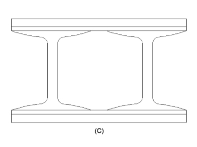
The built-up section ‘C’ is also used for heavy loads and small span.
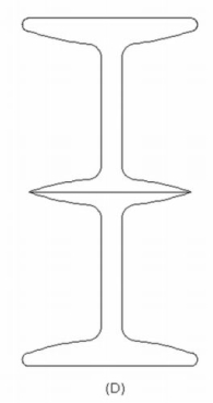
The built-up section ‘D’ is used for light loads and large spans.

The built-up sections ‘E’ & ‘F’ are provided for Gantry girders.
Design Procedure of the Built-up Beams design
Here are the simple steps that are to be followed for the design of Built-up Beams.
Step one
- The effective span and load required to be carried by the built-up beam are known.
- Maximum bending moment and shear force in built-up beams are calculated.
Step two
- Value of yield stress (fy) for structural steel is to be assumed.
- The permissible bending stress (sigma bc) is calculated.
Step three
- The required section modulus (Z) for the given beam section is calculated.
Step four
- From the steel table, a trial section for a beam is adopted having the modulus of section (Z) about 25% to 50% in excess of that requirement. The geometrical proportion of beam sections are noted.
Step five
- When the depth of the beam is noted, then the usually the practice is to select from ISI handbook No.1 (Steel tables).
- The strongest Rolled steel beam that will allow for necessary thickness of power plates at top and bottom.
Step six
- The area of power plate required is found out by trial-and-error method are by;
I = Ibeam + 2(Ap)(h/2) (h/2)
- For finding the area, divide the whole equation by h/2.
Step seven
- Width of cover plate and thickness are decided with the restriction of outstands.
Step Eight
- Check for bending stress/Actual bending compressive stress
(Sigma bc) calculated = (maximum bending moment/Gross MI) x Distance of extreme fibre in compression from Neutral Axis
= (M/Ixx) x y1
- Actual bending tension stress
sigma bt, cal = (sigma bc) cal x (gross area of tension flange/Net area of tension flange)
= Value should not exceed the permissible bending stress (sigma bc) or (sigma bt) = 0/66fy
Step nine
- Check for shear and Deflection
Q2) Explain Laterally restrained Beam?
A2)
Laterally Restrained Beams
Beams subjected to BM develop compressive and tensile forces and the flange subjected to compressive forces has the tendency to deflect laterally. This out of plane bending is called lateral bending or buckling of beams. The lateral bending of beams depends on the effective span between the restraints, minimum moment of inertia (Iyy) and its presence reduces the plastic moment capacity of the section.
Beams where lateral buckling of the compression flange are prevented are called laterally restrained beams. Such continuous lateral supports are provided in two ways:
i) The compression flange is connected to an RC slab throughout by shear connectors.
Ii) External lateral supports are provided at closer intervals to the compression flange so that it is as good continuous lateral support. Cl 8.2.1 (pg - 52 and 53) gives the specifications in this regard.
Design of such laterally supported beams are carried out using Clauses 8.2.1.2, 8.2.1.3, 8.2.1.5, 8.4, 8.4.1, 8.4.1.1, 8.4.2.1 and 5.6.1 (Deflection) In addition, the beams shall be checked for vertical buckling of web and web crippling. The design is simple, but lengthy and does not involve trial and error procedure.
Design steps:
- Calculate the factored load and the maximum bending moment and shear force
- Obtain the plastic section modulus required
Zp = (M*Vmo /Fy)
a suitable section for the beam-ISLB, ISMB, ISWB or suitable built-up sections (doubly symmetric only). (Doubly symmetric, singly symmetric and asymmetric- procedures are different)
3. Check for section classification such as plastic, compact, semi-compact or slender. Most of the sections are either plastic or compact. Flange and web criteria.

4. Calculate the design shear for the web and is given by

5. Calculate the design bending moment or moment resisted by the section (for plastic and compact)

6. Check for buckling
7. Check for crippling or bearing
8. Check for deflection
Q3) Explain un-restrained beam?
A3)
Laterally Unrestrained Beams
Beams subjected to BM develop compressive and tensile forces and the flange subjected to compressive forces has the tendency to deflect laterally. This out of plane bending is called lateral bending or buckling of beams. Lateral buckling of beams involves three kinds of deformations namely lateral bending, twisting and warping. The lateral bending of beams depends on the effective span between the restraints, minimum moment of inertia (Iyy) and can reduce the plastic moment capacity of the section.
The value of Mer can be calculated using the equations given in cl. 8.2.2.1 pg-54 for doubly symmetric c/s and annex E (pg 128-129) for c/s symmetrical about the minor axis. The design bending compressive strength can be calculated using a set of equations as specified.
Design steps:
1) Maximum shear force

Maximum bending force

2) Selecting of section
Assuming fbd = 130 N/mm^2

Properties:
Bf , tf , tw
Rmin
Zp
3) Classification of cross section
Flange

Web

Section is plastic or semi plastic
4) Design shear strength


Strength in bending Md need not be reduced due to shear
5) Design bending strength

6) Check Deflection limit

Q4) A simply supported beam of effective span 4 m carries a factored point load of 350 kN at mid span. The section is laterally supported throughout the span. Design the cross section using I section.
A4)
- Maximum shear force
V= reaction = W/2 = 1575 kN
2. maximum bending moment
M= WL/4= 350 kn-m
3. selection of cross section (using yielding criteria)
Zp required = 

Select an ISLB 500@75kg/m (using annex H Is 800-2007)
Sectional properties d=500 mm, Izz= 38549 x 1064 mm^4
Zp= 1773.7x 10^3 mm^3 > Zp required
Ze= 1545.2 X 10^3 mm^3
4. classification of section


5. Design shear strength


6. Design bending strength


7. Checks
- Web buckling

At a concentrated load W


Buckling class C
From table IS 800-2007 and fy= 250 Mpa
Kl/r | Fcd |
130 | 74.3 |
131.78 | ? |
140 | 66.2 |
Interpolation
Fcd= 72.85 N/mm^2
At concentrated point load


At reaction R


B. Web crippling


C. Deflection limits
Working load = 350/1.5 = 233.33Kn


Provide an ISLB 500@ 75 kg/m beam
Q5) What is Curtailment of flange plates?
A5)
In beam B.M is very less near to the simple support therefore, no need to provide same size of flange plate. To achieve economy flange thickness are curtailed near to the support called curtailment of flange.
Its position from support is calculating by equating the B.M at that section to the design bending strength at the section.
As the bending moment decreases towards the supports, some of the flange plates may be curtailed. There is not much difference in the effective depth after curtailment and will nearly equal to 'D', the depth over angles.
1- Curtailment of plates for a girder carrying uniformly distributed load-
Moment of resistance varies as effective flange area - i.e. area of flange A, 'plus 1/8 area of web (=Af+ Aw/d) d Let Ln be the theoretical length of the plate which is to be curtailed.
a = net area of plate to be curtailed plus the net area of plates above this as taken in full section.
A1 = total effective flange area. B.M. Diagram will be a parabola
M= k A1
Mn=K(A1-A)
M/(M-Mn) =L2/Ln2


2- Accurate method of curtailment-
In this method, the moment or resistance of the section after removing the plate is calculated and the point at which the B.M. Will be equal to this moment of resistance, will be the theoretical point at which the plate may be cut-off.

If M is the maximum B.M. And Mn is the moment of resistance of the section after removing the plate and Ln is the length of plate
M/(M-Mn) =L2/Ln2
Q6) Explain Design of welded plate girder?
A6)
Welded Plate Girders
Beams of long span subjected to heavy loads are encountered in buildings and bridges. For these beams, ready-made I sections are not suitable since their depth is limited due to buckling of the web. In this situation, girders are to be fabricated using flange and web plates as per requirement. Usually, the flange and web plates are connected by welding (Figure). Girders fabricated in this manner are known as welded plate girders and their depth to web thickness ratio (d/tw) may be up to 400. Because of higher d/tw, the buckling of the web becomes the major problem with these girders. To overcome this problem, different types of stiffeners are provided as shown in Figure
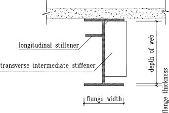
A welded plate girder is more efficient section as the whole area is effective in resisting loads. The flange plate is welded directly to the web and no flange angles are used. The flange plate is welded directly to the web and no flange angles are used. The box girders may also be fabricated by using two or more webs. It is uneconomical to use a number of thin cover plates as flanges one thick plate may be used as a flange and where it is desired to decrease the flange area, a thinner plate may be used. The thinner and thicker plates may then be butt welded. The self-weight in kg may be taken as – WL/400, where W is the total superimposed load in kg and 1 is the span in metres.
Types of Plate Girders
There may be exclusive classifications relying at the requirements used or relying on the character of the manufacturing of the girders.
There varieties of plate girders.
1. Reverted Plate Girder
2. Welded Plate Girder
Reverted Plate Girder
It is an aggregate of flanges, internet, and different vital stiffness. There are related via way of means of a mechanical method, revert, and plates aren't welded collectively.
- Generally, 90% of the shear is carried via way of means of the internet.
- Connection of the internet and the flange is stabilized via way of means of the angel sections reverted to the flange. Reverts want to be designed for the horizontal shear.
- The reverts that make the relationship among the internet and flange angles want to be designed for horizontal shear and vertical hundreds that carried out to the flange after they switch to the internet.
- Angle sections are used as internet stiffness in revert girders.
Application of Plate Girders
Plate girders are broadly used as assisting systems in exclusive regions. The following regions may be highlighted as key regions of use.
Bridge production
Plate girders are specifically utilized in railway and avenue bridges. Mostly the antique railway bridges may be highlighted as plate girder bridges.
In addition, field girder bridges, beam bridges, navy girder composite bridges, and half – thru plate girder bridges are taken into consideration because it uses.
- Ships
- Gantry beams
- Oil and fuel line platforms
- Load testing
- Cranes
- Lifting systems
Advantages of Plate Girder
- They may be used to hold heavy hundreds
- Speed production
- Grater balance
- High resistance to fatigue failures
- Easy to assemble while as compared with truss kind bridges
- Easy for maintenance
Disadvantages of Plate Girder
- They cannot be used to assist big spans
- Less architectural appearance
- A bit tough to deal within the course of the placement
- Production will be finished strictly according with the layout.
The articles have been written on Steel Beam Design as according to BS 5950 and Steel Beam Design Worked Example [Universal Beam] could be referred for extra facts on metal beam designs.
Further facts on metal beams may be studied from the article Types of metal beams.
Welded plate girders are maximum broadly utilized in production because of the convenience of manufacturing and its miles a far extra green sort of girder.
These sections are specifically utilized in bridge production. The plate girder bridge could be very stiff and it is able to retain very excessive hundred seven as resisting the lateral movements. This movement may be found within side the railway bridges. Further, they may be used to increase the field kind girders.
There are empirical or approximation strategies to decide the general peak of the plate girder and thickness of the flange and internet.
Components of welded Plate Girders
Mainly there are 5additives in a girder. The meeting of that 5-thing is the entire girder. The basic requirement is to make an “I” girder having very excessive bending and shear stiffens similarly to the alternative nearby buckling resistances.
- Web Plate
- Flange
- Stiffeners (bearing, longitudinal, and intermediate)
- Splices for flange and internet
- End Connection
Web Plate
The vertical plate of the girder is called the internet plate.
Its thickness is primarily based totally at the layout necessities and the peak can also be determined primarily based totally at the web page condition and as according to the hundreds carried out at the internet.
The internet typically includes the carried-out hundreds at the flange as shear forces. The impact of the internet isn't always usually taken into consideration while the layout for the bending.
The internet is at risk of buckling while thinner and better boom while the hundreds are carried out. Therefore, exclusive varieties of stiffness so as to be discussing on this article, are welded to the internet have its electricity.
Flange
There isn't any distinctiveness aside from using a separate plate for the flange. The flange plate could be welded or related via way of means of different method as mentioned beneath Neath exclusive varieties of plate girders.
Not like rolled sections, we connect the internet and the flange collectively to shape the plate girder.
The flange is layout to hold the bending movement and stiffener or extra plate are furnished as according to the layout necessities.
Stiffeners
Stiffeners are furnished to enhance structural potential heading off the nearby buckling failures. In addition, they may be used to hold the hundreds carried out to the beam till it allotted into the beam.
The following varieties of stiffeners can be found in those varieties of metal elements.
- Bearing stiffeners
- Longitudinal stiffeners
- Intermediate stiffeners
The bearing stiffeners are furnished at assist to distribute the assist response to the internet with none buckling failures. There are jacking stiffness except the bearing stiffeners for installations functions as indicated within side the following figure.
Steel plates welded within side the longitudinal and the transverse instructions also are used to reinforce the internet.
The vertical or the transverse stiffeners may be typically found in maximum of the metal beams that deliver heavy hundreds.
Splices for Flange and Web
It is the splice connection of the internet and the flange of the girder.
When the duration of the girder is less than the span, we must have a splice connection.
This is a second and shear shifting joint which gives beam continuation.
End Connection
End connection is the maximum tough a part of the structural detailing of a metal beam.
When there is continuation or if we are assisting the girder to a few assists, the relationship desires to be designed accordingly.
However, maximum of the time, plate girders are saved as definitely supported on the stop assist. In such situations, we must offer the stiffeners on the stop connection.
A comparable lay out system is followed while designing the endplates and the stiffener furnished vertically connecting the internet and the flange.
Q7) Explain Design of cross section?
A7)
1. Self weight of plate girder
The following imperical formula may be used to access the self weight of the beam

Where,
W= Total factored load
w = Factored self weight
2. Economical depth
Assuming that the moment M is carried out by flange only the economical depth d of girder may be found as given below


Where bf and tf are width and thickness of the flange

Taking

Then

For

(Differentiate area A w.r.t d and equated to zero)


In selecting value of k=d/tw the following codal provision will be useful
1) If 
2) Minimum web thickness based on serviceability requirement – cl. 8.6.1.1 ( IS 800-2000)
- When transverse stiffeners are not provided

b. When transverse stiffeners are provided
- When


2. When 

3. When 

4. When c>3d the web shall be considered unsiffned
c. When transverse stiffeners and longitudinal stiffeners at one level only are provided (0.2d from compression flange)
- When


2. When 

3. When 

d. When a second longitudinal stiffeners (located at neutral axis is provided)

3) Minimum web thickness based on compression flange buckling requirement (cl.8.6.1.2)
To avoid buckling of compression flnge into the web the ewb thickness shall satisfy the following
- When transverse stiffeners are not provided


2. When transverse stiffeners are provided an
- When


2. When 

3. Size of flanges
Assuming moment of resisted by flange only and using material safety factore for a plastic section
(Af.fy.d)/1.1 = M
Hence area of flange Af may be found. ( IS 800-2000)
Q8) A simply supported welded plate girder of an effective span of 24 m subjected to uniformly distributed load of 35 kn/m throughout the span excluding the self weight of plate girder assume compression flange laterally supported throughout the span and yield stress of steel is 250 MPa Design cross section of plate girder stiffeners.
A8)
1) Maximum bending moment and shear force
- Self weight of plate girder
Factored load = 35x 1.5 = 52.5 kN/m
Self weight of plate girder
W1= W/200 = 6.3 kN/m
Total uniformly distributed load on plate girder
w = 58.8 KN/m
b. Maximum bending moment
M= 58.8 x 24^2 /8 = 4233.6 kN/m
c. Maximum shear force
V= 58.8 x 24/2 = 705.6 Kn
2) Initial sizing of plate girder
- Design of web plate
If stiffener spacing c is in between d and 3d, where d is depth of web the serviceability requirement is
K = d/tw< 200 considering k=190
Economical depth
S = [ Mk/fy]^(1/3) = 1473.29 mm= 1500mm
Tw = 1500/190 = 8 mm
Provide 1500 mm deep and 8 mm thick web plate.
Provide intermediate stiffeners at a spacing of 2000 mm center to center (3d>c<d)
b. Design of flange
Assuming the flange resist the moment


Maximum width = d/3 = 15000/3 = 500mm
Provide 400 mm width of flange


Provide 32 mm thick flange plate
- Check for shear buckling of web
Using simple post critical method as per cl.8.4.2.2 of IS 800-2007


2. Shear capacity of end panel


The end panel to be check as a beam spanning between the flange to resist Rft and Mft


End panel can carry the shear due to anchoring force


Hence end panel can carry the bending moment due to anchor force
3. Design of end stiffeners
Reaction at ends= 705.6 kN
Compressive force due Mtf
Mtf/c= 118.33 kN
Total compression = 705.6 +118.33 = 824kN
Strength of the stiffners as per clause8.7.2.2 IS 800-2000


Provide 180 mm wide and 10 mm thick flats on either side of web Then Aq provided is

Check for outstand
It should not be more than 20 tq
Since it is more than 14 tq, 14 x10 = 140 mm
Core area of each stiffener = 140 x10 = 1400 mm^2
4. Design of intermediate stiffeners
As the shear force reducing towards mid span the first stiffener from end is critical. Since first intermediate stiffener is at c=2m from end
Shear force on the stiffeners V
R-2w= 705.6 – 2x58.8 = 588 kN
The ratio c/d = 200/15000= 1.33<
Hence required minimum moment of inertia

Provide intermediate stiffener of size 120 mm wide and 10mm thick which satisfy the condition of outstand

Hence o.k
Checking for buckling
Shear buckling resistance of web alone
Vcr= 469.8 kN
Shear strength of stiffener alone required

Buckling resistance of intermediate stiffener as per clause 8.7.1.5 of IS 800-2007
Considering
20 tw= 160 mm width of web on both side along with stiffener

Area = A= (2x120x10+2x160x8) = 4960mm^2
r= 50.66mm
KL/r= 20.72
From Is 9c of IS 800-2007
Fcd= 223.87mpa
Buckling resistance
223.78 x 4960/1000= 1109.97>107.45
Hence Safe.
Unit - 3
Unit - 3
Unit - 3
Unit - 3
Unit - 3
Unit - 3
Design of simple and built up beams
Q1) What is Design of simple and built up beams?
A1)
Design of simple
Beams are structural elements subjected to transverse loads in the plane of bending causing bending moments and shear forces.
Symmetrical b sections about z-z axis (major axis) are economical and geometrical properties of such sections are available in SP (6).
The compression flange of the beams can be laterally supported (restrained) or laterally unsupported (unrestrained) depending upon whether restraints are provided or not.
The beams are designed for maximum BM and checked for maximum SF, local effects such as vertical buckling and crippling of webs and deflection. Section 8 (IS 800-2007) shall be followed in the design of such bending members.
Types of Sections
Beams can be different cross sections depending on the span and loadings.
1. Simple I section
2. I section with cover plate
3. Two I section with cover plate
4. Built-up I section
5. Gantry girder
6. Box sections
7. Castled beams
8. Two I placed one above the other
1) Simple I section: Use of simple I section is normal span and loading
2) I section with cover plate: Use of I section with cover plate is heavy load and larger span
3) Two I section with cover plate: it is use of very heavy load with large span
4) Built-up I section: it is used to plate girder where span exceed 20 m and loads are heavy.
5) Gantry girder: Gantry girder is use for movable heavy loads, lift loads etc.
6) Box sections: It is use for service lines
7) Castled beams: It is use for light loads and large span
8) Two I placed one above the other: It is used for light loading with large span
Behaviour of Beam in Flexure
In order to expect the flexural behavior of any brittle fabric like concrete, load deflection technique on 3 factors become essential. The 3 factor technique is the manner to compute the deflections because of implemented masses so as to investigate the flexural behavior.
RCC beam are efficiently used as structural participants in diverse constructions. RCC is a homogeneous material which is having diverse properties.
RCC beams are classified as under strengthened, balanced and over strengthened sections on the evaluation basis. In RCC each concrete and steels will reaches the pressure and corresponding lines because of outside subjected hundreds concurrently.
When in an RCC beam, if the metallic has a tendency to fail earlier than the pressure in concrete reaches the maximum permissible pressure such beams are known as under strengthened sections. If each concrete and metallic reaches the permissible pressure values concurrently such beams are taken into consideration as balanced sections. If the concrete has a tendency to fail earlier than the pressure in metallic reaches the maximum permissible pressure such beams are taken into consideration as over strengthened sections. In the following article primarily based totally on the laboratory experimental evaluation the flexure behavior of diverse sections are discovered through damaging methods.
DESIGN CRITERIA
The primary layout criterion for any form of shape is safety, serviceability and economy. Due to these primary esteem properties of RCC elements, they are abundantly used in all structural applications. For the structural use of RCC elements it must obey the following parameters. The shape must be secure and economical that it can perfectly resist both tension and compressive stress. The shape must be stiff and look like unblemished such that it ought to be resisted the bending moments and shear forces because of outside applied masses.
The shape must be economical by means of it can be able to resist all type of stress and availability of substances to make RCC. In order to are expecting the secure and monetary situations of RCC it's far essential to evaluate the situations of remaining masses and corresponding deflections below precise constrains.
To attain the applicable outcomes one had to behavior an experimental analysis. When an RCC beam is subjected to a few outside loadings the beam tends to bend with a few deflection due to loading. At any point in the cross section of the beam is considered the pressure distribution can be such that everyone the fibers above the impartial axis by skip thru the CG are in compression, while all of the fibers beneath the impartial axis are in tension.

Built up beams
A built-up beam is likewise referred to as compound beam.
The built-up beams are used whilst the span, load and corresponding bending second are of such magnitudes that rolled metal beam segment will become insufficient to offer required segment modulus.
Built-up beams also are used whilst rolled metal beams are insufficient for restricted intensity.
In constructing construction, the intensity of beam is restricted with the aid of using an area furnished with the aid of using the architect.
Drawing beam of small intensity do now no longer offer required segment modulus. Therefore, plates are connected to the beams.
The energy of rolled metal beams is multiplied with the aid of using including plates to its flange that's one of the techniques forming built-in segment.
The different technique is to compound some of rolled metal sections themselves.
The built-up sections shown in figure’ A’ and ‘B’ are used for heavy loads and small spans.
The built-up section ‘C’ is also used for heavy loads and small span.
The built-up section ‘D’ is used for light loads and large spans.
The built-up sections ‘E’ & ‘F’ are provided for Gantry girders.
Design Procedure of the Built-up Beams design
Here are the simple steps that are to be followed for the design of Built-up Beams.
Step one
- The effective span and load required to be carried by the built-up beam are known.
- Maximum bending moment and shear force in built-up beams are calculated.
Step two
- Value of yield stress (fy) for structural steel is to be assumed.
- The permissible bending stress (sigma bc) is calculated.
Step three
- The required section modulus (Z) for the given beam section is calculated.
Step four
- From the steel table, a trial section for a beam is adopted having the modulus of section (Z) about 25% to 50% in excess of that requirement. The geometrical proportion of beam sections are noted.
Step five
- When the depth of the beam is noted, then the usually the practice is to select from ISI handbook No.1 (Steel tables).
- The strongest Rolled steel beam that will allow for necessary thickness of power plates at top and bottom.
Step six
- The area of power plate required is found out by trial-and-error method are by;
I = Ibeam + 2(Ap)(h/2) (h/2)
- For finding the area, divide the whole equation by h/2.
Step seven
- Width of cover plate and thickness are decided with the restriction of outstands.
Step Eight
- Check for bending stress/Actual bending compressive stress
(Sigma bc) calculated = (maximum bending moment/Gross MI) x Distance of extreme fibre in compression from Neutral Axis
= (M/Ixx) x y1
- Actual bending tension stress
sigma bt, cal = (sigma bc) cal x (gross area of tension flange/Net area of tension flange)
= Value should not exceed the permissible bending stress (sigma bc) or (sigma bt) = 0/66fy
Step nine
- Check for shear and Deflection
Q2) Explain Laterally restrained Beam?
A2)
Laterally Restrained Beams
Beams subjected to BM develop compressive and tensile forces and the flange subjected to compressive forces has the tendency to deflect laterally. This out of plane bending is called lateral bending or buckling of beams. The lateral bending of beams depends on the effective span between the restraints, minimum moment of inertia (Iyy) and its presence reduces the plastic moment capacity of the section.
Beams where lateral buckling of the compression flange are prevented are called laterally restrained beams. Such continuous lateral supports are provided in two ways:
i) The compression flange is connected to an RC slab throughout by shear connectors.
Ii) External lateral supports are provided at closer intervals to the compression flange so that it is as good continuous lateral support. Cl 8.2.1 (pg - 52 and 53) gives the specifications in this regard.
Design of such laterally supported beams are carried out using Clauses 8.2.1.2, 8.2.1.3, 8.2.1.5, 8.4, 8.4.1, 8.4.1.1, 8.4.2.1 and 5.6.1 (Deflection) In addition, the beams shall be checked for vertical buckling of web and web crippling. The design is simple, but lengthy and does not involve trial and error procedure.
Design steps:
- Calculate the factored load and the maximum bending moment and shear force
- Obtain the plastic section modulus required
Zp = (M*Vmo /Fy)
a suitable section for the beam-ISLB, ISMB, ISWB or suitable built-up sections (doubly symmetric only). (Doubly symmetric, singly symmetric and asymmetric- procedures are different)
3. Check for section classification such as plastic, compact, semi-compact or slender. Most of the sections are either plastic or compact. Flange and web criteria.

4. Calculate the design shear for the web and is given by

5. Calculate the design bending moment or moment resisted by the section (for plastic and compact)

6. Check for buckling
7. Check for crippling or bearing
8. Check for deflection
Q3) Explain un-restrained beam?
A3)
Laterally Unrestrained Beams
Beams subjected to BM develop compressive and tensile forces and the flange subjected to compressive forces has the tendency to deflect laterally. This out of plane bending is called lateral bending or buckling of beams. Lateral buckling of beams involves three kinds of deformations namely lateral bending, twisting and warping. The lateral bending of beams depends on the effective span between the restraints, minimum moment of inertia (Iyy) and can reduce the plastic moment capacity of the section.
The value of Mer can be calculated using the equations given in cl. 8.2.2.1 pg-54 for doubly symmetric c/s and annex E (pg 128-129) for c/s symmetrical about the minor axis. The design bending compressive strength can be calculated using a set of equations as specified.
Design steps:
1) Maximum shear force

Maximum bending force

2) Selecting of section
Assuming fbd = 130 N/mm^2

Properties:
Bf , tf , tw
Rmin
Zp
3) Classification of cross section
Flange

Web

Section is plastic or semi plastic
4) Design shear strength


Strength in bending Md need not be reduced due to shear
5) Design bending strength

6) Check Deflection limit

Q4) A simply supported beam of effective span 4 m carries a factored point load of 350 kN at mid span. The section is laterally supported throughout the span. Design the cross section using I section.
A4)
- Maximum shear force
V= reaction = W/2 = 1575 kN
2. maximum bending moment
M= WL/4= 350 kn-m
3. selection of cross section (using yielding criteria)
Zp required = 

Select an ISLB 500@75kg/m (using annex H Is 800-2007)
Sectional properties d=500 mm, Izz= 38549 x 1064 mm^4
Zp= 1773.7x 10^3 mm^3 > Zp required
Ze= 1545.2 X 10^3 mm^3
4. classification of section


5. Design shear strength


6. Design bending strength


7. Checks
- Web buckling

At a concentrated load W


Buckling class C
From table IS 800-2007 and fy= 250 Mpa
Kl/r | Fcd |
130 | 74.3 |
131.78 | ? |
140 | 66.2 |
Interpolation
Fcd= 72.85 N/mm^2
At concentrated point load


At reaction R


B. Web crippling


C. Deflection limits
Working load = 350/1.5 = 233.33Kn


Provide an ISLB 500@ 75 kg/m beam
Q5) What is Curtailment of flange plates?
A5)
In beam B.M is very less near to the simple support therefore, no need to provide same size of flange plate. To achieve economy flange thickness are curtailed near to the support called curtailment of flange.
Its position from support is calculating by equating the B.M at that section to the design bending strength at the section.
As the bending moment decreases towards the supports, some of the flange plates may be curtailed. There is not much difference in the effective depth after curtailment and will nearly equal to 'D', the depth over angles.
1- Curtailment of plates for a girder carrying uniformly distributed load-
Moment of resistance varies as effective flange area - i.e. area of flange A, 'plus 1/8 area of web (=Af+ Aw/d) d Let Ln be the theoretical length of the plate which is to be curtailed.
a = net area of plate to be curtailed plus the net area of plates above this as taken in full section.
A1 = total effective flange area. B.M. Diagram will be a parabola
M= k A1
Mn=K(A1-A)
M/(M-Mn) =L2/Ln2


2- Accurate method of curtailment-
In this method, the moment or resistance of the section after removing the plate is calculated and the point at which the B.M. Will be equal to this moment of resistance, will be the theoretical point at which the plate may be cut-off.

If M is the maximum B.M. And Mn is the moment of resistance of the section after removing the plate and Ln is the length of plate
M/(M-Mn) =L2/Ln2
Q6) Explain Design of welded plate girder?
A6)
Welded Plate Girders
Beams of long span subjected to heavy loads are encountered in buildings and bridges. For these beams, ready-made I sections are not suitable since their depth is limited due to buckling of the web. In this situation, girders are to be fabricated using flange and web plates as per requirement. Usually, the flange and web plates are connected by welding (Figure). Girders fabricated in this manner are known as welded plate girders and their depth to web thickness ratio (d/tw) may be up to 400. Because of higher d/tw, the buckling of the web becomes the major problem with these girders. To overcome this problem, different types of stiffeners are provided as shown in Figure
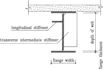
A welded plate girder is more efficient section as the whole area is effective in resisting loads. The flange plate is welded directly to the web and no flange angles are used. The flange plate is welded directly to the web and no flange angles are used. The box girders may also be fabricated by using two or more webs. It is uneconomical to use a number of thin cover plates as flanges one thick plate may be used as a flange and where it is desired to decrease the flange area, a thinner plate may be used. The thinner and thicker plates may then be butt welded. The self-weight in kg may be taken as – WL/400, where W is the total superimposed load in kg and 1 is the span in metres.
Types of Plate Girders
There may be exclusive classifications relying at the requirements used or relying on the character of the manufacturing of the girders.
There varieties of plate girders.
1. Reverted Plate Girder
2. Welded Plate Girder
Reverted Plate Girder
It is an aggregate of flanges, internet, and different vital stiffness. There are related via way of means of a mechanical method, revert, and plates aren't welded collectively.
- Generally, 90% of the shear is carried via way of means of the internet.
- Connection of the internet and the flange is stabilized via way of means of the angel sections reverted to the flange. Reverts want to be designed for the horizontal shear.
- The reverts that make the relationship among the internet and flange angles want to be designed for horizontal shear and vertical hundreds that carried out to the flange after they switch to the internet.
- Angle sections are used as internet stiffness in revert girders.
Application of Plate Girders
Plate girders are broadly used as assisting systems in exclusive regions. The following regions may be highlighted as key regions of use.
Bridge production
Plate girders are specifically utilized in railway and avenue bridges. Mostly the antique railway bridges may be highlighted as plate girder bridges.
In addition, field girder bridges, beam bridges, navy girder composite bridges, and half – thru plate girder bridges are taken into consideration because it uses.
- Ships
- Gantry beams
- Oil and fuel line platforms
- Load testing
- Cranes
- Lifting systems
Advantages of Plate Girder
- They may be used to hold heavy hundreds
- Speed production
- Grater balance
- High resistance to fatigue failures
- Easy to assemble while as compared with truss kind bridges
- Easy for maintenance
Disadvantages of Plate Girder
- They cannot be used to assist big spans
- Less architectural appearance
- A bit tough to deal within the course of the placement
- Production will be finished strictly according with the layout.
The articles have been written on Steel Beam Design as according to BS 5950 and Steel Beam Design Worked Example [Universal Beam] could be referred for extra facts on metal beam designs.
Further facts on metal beams may be studied from the article Types of metal beams.
Welded plate girders are maximum broadly utilized in production because of the convenience of manufacturing and its miles a far extra green sort of girder.
These sections are specifically utilized in bridge production. The plate girder bridge could be very stiff and it is able to retain very excessive hundred seven as resisting the lateral movements. This movement may be found within side the railway bridges. Further, they may be used to increase the field kind girders.
There are empirical or approximation strategies to decide the general peak of the plate girder and thickness of the flange and internet.
Components of welded Plate Girders
Mainly there are 5additives in a girder. The meeting of that 5-thing is the entire girder. The basic requirement is to make an “I” girder having very excessive bending and shear stiffens similarly to the alternative nearby buckling resistances.
- Web Plate
- Flange
- Stiffeners (bearing, longitudinal, and intermediate)
- Splices for flange and internet
- End Connection
Web Plate
The vertical plate of the girder is called the internet plate.
Its thickness is primarily based totally at the layout necessities and the peak can also be determined primarily based totally at the web page condition and as according to the hundreds carried out at the internet.
The internet typically includes the carried-out hundreds at the flange as shear forces. The impact of the internet isn't always usually taken into consideration while the layout for the bending.
The internet is at risk of buckling while thinner and better boom while the hundreds are carried out. Therefore, exclusive varieties of stiffness so as to be discussing on this article, are welded to the internet have its electricity.
Flange
There isn't any distinctiveness aside from using a separate plate for the flange. The flange plate could be welded or related via way of means of different method as mentioned beneath Neath exclusive varieties of plate girders.
Not like rolled sections, we connect the internet and the flange collectively to shape the plate girder.
The flange is layout to hold the bending movement and stiffener or extra plate are furnished as according to the layout necessities.
Stiffeners
Stiffeners are furnished to enhance structural potential heading off the nearby buckling failures. In addition, they may be used to hold the hundreds carried out to the beam till it allotted into the beam.
The following varieties of stiffeners can be found in those varieties of metal elements.
- Bearing stiffeners
- Longitudinal stiffeners
- Intermediate stiffeners
The bearing stiffeners are furnished at assist to distribute the assist response to the internet with none buckling failures. There are jacking stiffness except the bearing stiffeners for installations functions as indicated within side the following figure.
Steel plates welded within side the longitudinal and the transverse instructions also are used to reinforce the internet.
The vertical or the transverse stiffeners may be typically found in maximum of the metal beams that deliver heavy hundreds.
Splices for Flange and Web
It is the splice connection of the internet and the flange of the girder.
When the duration of the girder is less than the span, we must have a splice connection.
This is a second and shear shifting joint which gives beam continuation.
End Connection
End connection is the maximum tough a part of the structural detailing of a metal beam.
When there is continuation or if we are assisting the girder to a few assists, the relationship desires to be designed accordingly.
However, maximum of the time, plate girders are saved as definitely supported on the stop assist. In such situations, we must offer the stiffeners on the stop connection.
A comparable lay out system is followed while designing the endplates and the stiffener furnished vertically connecting the internet and the flange.
Q7) Explain Design of cross section?
A7)
1. Self weight of plate girder
The following imperical formula may be used to access the self weight of the beam

Where,
W= Total factored load
w = Factored self weight
2. Economical depth
Assuming that the moment M is carried out by flange only the economical depth d of girder may be found as given below


Where bf and tf are width and thickness of the flange

Taking

Then

For

(Differentiate area A w.r.t d and equated to zero)


In selecting value of k=d/tw the following codal provision will be useful
1) If 
2) Minimum web thickness based on serviceability requirement – cl. 8.6.1.1 ( IS 800-2000)
- When transverse stiffeners are not provided

b. When transverse stiffeners are provided
- When


2. When 

3. When 

4. When c>3d the web shall be considered unsiffned
c. When transverse stiffeners and longitudinal stiffeners at one level only are provided (0.2d from compression flange)
- When


2. When 

3. When 

d. When a second longitudinal stiffeners (located at neutral axis is provided)

3) Minimum web thickness based on compression flange buckling requirement (cl.8.6.1.2)
To avoid buckling of compression flnge into the web the ewb thickness shall satisfy the following
- When transverse stiffeners are not provided


2. When transverse stiffeners are provided an
- When


2. When 

3. Size of flanges
Assuming moment of resisted by flange only and using material safety factore for a plastic section
(Af.fy.d)/1.1 = M
Hence area of flange Af may be found. ( IS 800-2000)
Q8) A simply supported welded plate girder of an effective span of 24 m subjected to uniformly distributed load of 35 kn/m throughout the span excluding the self weight of plate girder assume compression flange laterally supported throughout the span and yield stress of steel is 250 MPa Design cross section of plate girder stiffeners.
A8)
1) Maximum bending moment and shear force
- Self weight of plate girder
Factored load = 35x 1.5 = 52.5 kN/m
Self weight of plate girder
W1= W/200 = 6.3 kN/m
Total uniformly distributed load on plate girder
w = 58.8 KN/m
b. Maximum bending moment
M= 58.8 x 24^2 /8 = 4233.6 kN/m
c. Maximum shear force
V= 58.8 x 24/2 = 705.6 Kn
2) Initial sizing of plate girder
- Design of web plate
If stiffener spacing c is in between d and 3d, where d is depth of web the serviceability requirement is
K = d/tw< 200 considering k=190
Economical depth
S = [ Mk/fy]^(1/3) = 1473.29 mm= 1500mm
Tw = 1500/190 = 8 mm
Provide 1500 mm deep and 8 mm thick web plate.
Provide intermediate stiffeners at a spacing of 2000 mm center to center (3d>c<d)
b. Design of flange
Assuming the flange resist the moment


Maximum width = d/3 = 15000/3 = 500mm
Provide 400 mm width of flange


Provide 32 mm thick flange plate
- Check for shear buckling of web
Using simple post critical method as per cl.8.4.2.2 of IS 800-2007


2. Shear capacity of end panel


The end panel to be check as a beam spanning between the flange to resist Rft and Mft


End panel can carry the shear due to anchoring force


Hence end panel can carry the bending moment due to anchor force
3. Design of end stiffeners
Reaction at ends= 705.6 kN
Compressive force due Mtf
Mtf/c= 118.33 kN
Total compression = 705.6 +118.33 = 824kN
Strength of the stiffners as per clause8.7.2.2 IS 800-2000


Provide 180 mm wide and 10 mm thick flats on either side of web Then Aq provided is

Check for outstand
It should not be more than 20 tq
Since it is more than 14 tq, 14 x10 = 140 mm
Core area of each stiffener = 140 x10 = 1400 mm^2
4. Design of intermediate stiffeners
As the shear force reducing towards mid span the first stiffener from end is critical. Since first intermediate stiffener is at c=2m from end
Shear force on the stiffeners V
R-2w= 705.6 – 2x58.8 = 588 kN
The ratio c/d = 200/15000= 1.33<
Hence required minimum moment of inertia

Provide intermediate stiffener of size 120 mm wide and 10mm thick which satisfy the condition of outstand

Hence o.k
Checking for buckling
Shear buckling resistance of web alone
Vcr= 469.8 kN
Shear strength of stiffener alone required

Buckling resistance of intermediate stiffener as per clause 8.7.1.5 of IS 800-2007
Considering
20 tw= 160 mm width of web on both side along with stiffener

Area = A= (2x120x10+2x160x8) = 4960mm^2
r= 50.66mm
KL/r= 20.72
From Is 9c of IS 800-2007
Fcd= 223.87mpa
Buckling resistance
223.78 x 4960/1000= 1109.97>107.45
Hence Safe.