Unit - 2
Simple, Compound, Reverse Curves and Vertical Curves
Q1) What is simple curve?
A1)
Simple Curves
Curves are everyday bends furnished with inside the strains of verbal exchange like roads, railways etc. and additionally in canals to result in the sluggish alternate of course.
They also are used with inside the vertical aircraft in any respect adjustments of grade to keep away from the abrupt alternate of grade on the apex.
Curves furnished with inside the horizontal aircraft to have the sluggish alternate in course are referred to as Horizontal curves, while the ones furnished with inside the vertical aircraft to gain the sluggish alternate in grade are referred to as vertical curves.
Curves are laid out at the floor alongside the center line of the work. They can be round or parabolic.
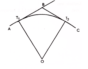
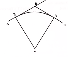
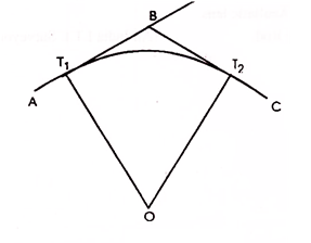
A simple curve consists of a single arc of a circle connecting two straights. It has radius of the same magnitude throughout. In fig. T1 D T2 is the simple curve with T1O as its radius.
Q2) What are the elements if simple curve?
A2)
Elements of simple curve:
Figure shows the elements of a simple curve. They are described as follows, and their abbreviations are given in parentheses.
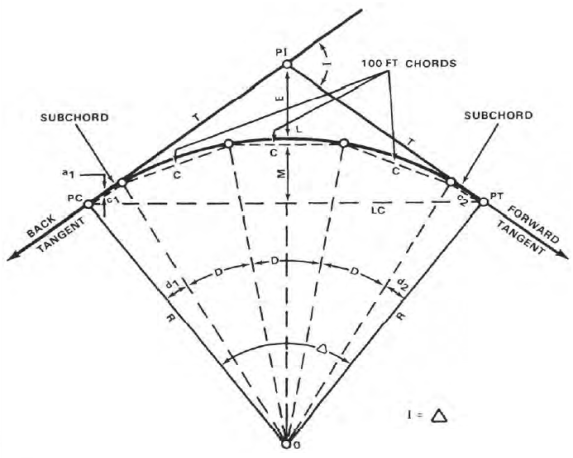
Figure. Elements of a simple curve
Point of Intersection (PI)
The factor of intersection marks the factor in which the lower back and ahead tangents intersect. The surveyor shows it as one of the stations at the initial traverse.
Intersecting Angle (I)
The intersecting attitude is the deflection attitude on the PI.
Radius (R)
The radius is the radius of the circle of which the curve is an arc.
Point of Curvature (PC)
The factor of curvature is the factor in which the round curve begins. The lower back tangent is tangent to the curve at this factor.
Point of Tangency (PT)
The factor of tangency is the stop of the curve. The ahead tangent is tangent to the curve at this factor.
Length of Curve (L)
The period of curve is the gap from the PC to the PT measured alongside the curve.
Tangent Distance (T)
The tangent distance is the gap alongside the tangents from the PI to the PC or PT. These distances are identical on an easy curve.
Central Angle (Δ)
The valuable attitude is the attitude fashioned through radii drawn from the middle of the circle (0) to the PC and PT. The valuable attitude is identical in fee to the I attitude.
Long Chord (LC)
The lengthy chord is the chord from the PC to the PT.
External Distance (E)
The outside distance is the gap from the PI to the midpoint of the curve. The outside distance bisects the indoors attitude on the PI.
Middle Ordinate (M)
The center ordinate is the gap from the midpoint of the curve to the midpoint of the lengthy chord. The extension of the center ordinate bisects the valuable attitude.
Degree of Curve (D)
The diploma of curve defines the “sharpness” or “flatness” of the curve (determine 3). There are definitions usually in use for diploma of curve, the arc definition and the chord definition.
Arc definition.
The arc definition states that the diploma of curve (D) is the attitude fashioned through radii drawn from the middle of the circle (factor O, determine 3) to the ends of an arc one hundred ft. Or 30.forty eight meters lengthy. In this definition, the diploma of curve and radius are inversely proportional the use of the subsequent formula:

Circumference = 2 π Radius
π = 3.141592654
Chords
On curves with lengthy radii, it's miles impractical to stake the curve via way of means of finding the middle of the circle and swinging the arc with a tape.
The surveyor lays those curves out via way of means of staking the ends of a chain of chords (parent 4). Since the ends of the chords lie at the circumference of the curve, the surveyor defines the arc with inside the field.
The duration of the chords varies with the diploma of curve. To lessen the discrepancy among the arc distance and chord distance, the surveyor makes use of the subsequent chord lengths:
The chord lengths above are the most distances wherein the discrepancy among the arc duration and chord duration will fall with inside the allowable blunders for taping, that's 0. 02 foot in keeping with one hundred ft. On maximum creation surveys.
Degree of Curve | Radius Feet | Radius Meters | Chord Feet | Lengths Meters |
From 1 - 3 | 5,730 – 1,910 | 1,745 - 585 | 100 | 30.0 |
3 - 8 | 1,910 - 720 | 585 - 220 | 50 | 15.0 |
8 - 16 | 720 - 360 | 220 - 110 | 25 | 7.5 |
Over 16 | 360 - 150 | 110 - 45 | 10 | 3 |
Deflection Angles
The deflection angles are the angles among a tangent and the ends of the chords from the PC. The surveyor makes use of them to discover the path wherein the chords are to be laid out. The overall of the deflection angles is continually same to 1 1/2 of the I angle. This overall serves as a test at the computed deflection angles.
Q3) What are the methods of curve ranging?
A3)
Methods of curve ranging
The strategies of starting off curves can be divided in classes in line with the tool hired.
1. Linear or chain and tape method: - Linear strategies are the ones in which the curve is about out with chain and tape only.
2. Angular or instrumental method: - instrumental strategies are the ones in which theodolite without or with a series is hired to set out curve.
1. Linear or chain and tape method
The following are the methods of setting out simple circular curves by linear methods and by the use of chain and tape:
1. By ordinates from the Long chord
2. By Successive Bisection of Arcs.
3. By Offsets from the Tangents.
4. By Offsets from Chords Produced.
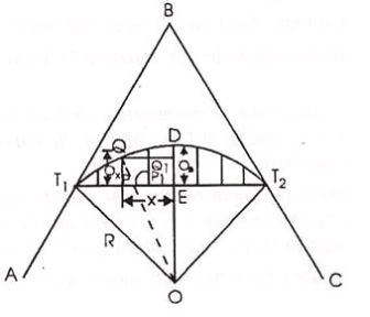
1. By Ordinates from the Long Chord:
Let T1T2=L= the length of the Long chord
ED= O0= the offset at mid-point (e) of the long chord (the versed sine)
PQ=Ox= the offset at distance x from E
Draw QQ1 parallel to T1 T2 meeting DE at Q1
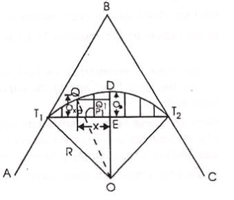
Join OQ cutting T1T2 in P1
From the OQQ1 , OQ2 = QQ12 + OQ12
But OQ = R ; OQ1 = x
And OQ1 = OE + EQ1 = (R – Q3) + Ox
R2 = x2 {(R – O0) + O0}2
Or (R – O0) + Ox = (R2 – x2)
Hence Ox = (R2 – x2)-(R - O)
(Exact) … …(Eqn. 11.10)
Where O0 = ED = OD – OE
= R -  … …(Eqn. 11. 10, a)
When the radius of the curve is large as compared with the length of the long chord, the offset may be equated by the approximate formula which is derived as follows:
Here Ox is assumed to be equal to the radial ordinate QP1.
QP 2R = T1P PT2
Or QP1 = (T1P PT2)/2R
Now T1P = x, and PT2 = L – x
Qx = x(L – x)/2R (approximate) …… ……..(Eqn. 11.11)
2. By Successive Bisections of Arcs:
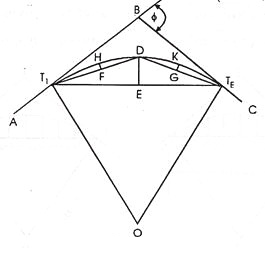
It is also known as Versing Method. Join T1 T2 and bisect it at E. Set out the offset ED the versed since equal to:
R(1 – cos /2, thus fixing the point Don the curve
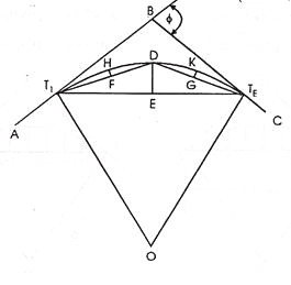
Join T1D and DT2 and bisect them at F and G respectively. Then set outsets FH and GK at F and G each equal to R(1 – cos /4) thus fixing two more points H and K on the curve. Then each of the offsets to be set out at mid points of the chords T1H, HD, DK and KT2 is equal to R(1 – cos /8).By repeating this process, set out as many point as are required.
This method is suitable where the ground outside the curve is not favourable to the tangents.
3. By Offsets from the Tangents:
The offsets may be either radial or perpendicular to the tangents.
(a) By Radial Offsets:
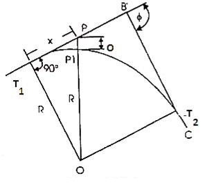
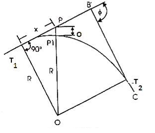
Let Ox = PP1 = the radial offset at P at a distance of x from T1 along the tangent AB
PP1 = OP – OP1 , where OP =  and OP1 = R
Ox =  - R (exact) ………(Eqn . 11. 12)
When the radius is large, the offsets may be calculated by the approximate formula, which may be derived as under:
PT12 = PP1 (2R + PP1)
i.e. x2 = Ox (2R + Ox ) = 2ROx + Ox2
Since Ox2 is very small as compared with 2R, it may be neglected.
x2 = 2R.Ox
Or Ox = x2/2R (approximate) ……(Eqn. 11.13)
(b) By Offsets perpendicular to the Tangents:
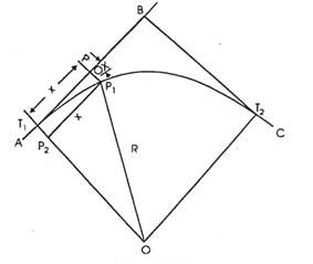
Let Ox = PP1 = the perpendicular offset at P at a distance of x from T1 along the tangent AB.
Draw P1P2 parallel to BT1, meeting OT1 at P2
Then P1P2 = PT1 = x; T1P2 = PP1 = Ox.
Now T1P2 = OT1 – OP2
Where OT1 = R, and OP2 = 
Ox = R -  (exact) …..(Eqn. 11.14)
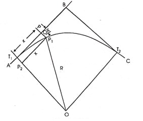
The approximate formula may be obtained similarly as in (a) above,
Ox = x2/2R (approximate) ………(Eqn. 11.5)
Q4) Explain procedure of setting out the curve.
A4)
(i) Locate the tangent points T1 and T2.
(ii) Measure equal distances, say 15 or 30 m along the tangent from T1.
(iii) Set out the offsets calculated by any of the above methods at each distance, thus obtaining the required points on the curve.
(iv) Continue the process until the apex of the curve is reached.
(v) Set out the other half of the curve from the second tangent.
This method is suitable for setting out sharp curves where the ground outside the curve is favorable for chaining.
By Offsets from Chords Produced:
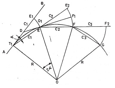
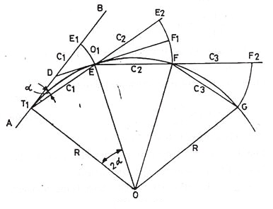
Let AB = the first tangent; T1 = the first tangent point E, F, G etc on the successive points on the curve T1E = T1E1 = C1 = the first chords.
EF, FG, etc. = the successive chords of length C2, C3 etc., each being equal to the full chord.
∠ BT1E = α in radians = the angle between the tangents BT1 and the first chord T1E.
E1E = O1 = the offset from the tangent BT1
E2F = O2 = the offset from the chord T1E produced.
Produce T1E to E2 such tharEE2 = C2. Draw the tangent DEF1 at E meeting the first tangent at D and E2F at F1.
∠BT1E= α in the radians= the angle between the tangents BT1and the first chord T1E.
E1E=O1= the offset from the tangent BT1
E2F=O2= the offset from the chord T1E produced.
Produce T1E to E2 such that EE2= C2.Draw the tangent DEF1at E meeting the first tangent at D and E2Fat F1.
The formula for the offsets may be derived a under:
∠ BT1E=x
∠T1OE=2x
The angle subtended by any chord at the center is twice the angle between the chord and the tangent

But arc T1E is approximately equal to chord T1E = C
C1/R = 2α
Or α = C1/2R
Also 
But arc EE is approximately equal to chord E1E = =O1
O1 = C1 α
Putting here the value of α as calculated above.
O1 = C1 C1/2R = C12/2R ………….(Eqn. 11.16)
O2 = offset E2F = E2F1 + F1F
To find out F2F1, consider the two triangles TEE1 and EF1E2
∠E2EF1 = ∠DET1 (vertically opposite angles):
∠DET1 = ∠DT1E, since DT1 = DE, both being tangents to the circle.
∠E1EF1 = ∠DET1 = ∠DT1E
Both the s being nearly isosceles, may be taken as approximately similar,

∠α
i.e., 
Or E2F1 = (C2 O1)/C2
= C2/C1 C12/2R = (C1C2)/2R
F1F being the offset from the tangent at E, is equal to
EF2/2R = C22/2R
The second offset, O2 = (C1C2)/2R + C22/2R,
 …….(Eqn. 11.17)
Similarly the third offset, O3 = 
Since C2 = C3 = C1 ……….etc,
O3 = C22/R ……………(Eqn. 11. 18)
Each of the remaining offsets O4,O5 etc expect the last one (On) is equal to O3. Since the length of the last chord is usually less than the length of the chord, the last offset,

Q5) Explain procedure of Setting out the Curve
A5)
(i) Locate the tangent points (T1 and T2) and find out their changes. From these changes, calculate lengths of first and last sub-chords and find out the offsets by using the equations 11.16 to 11.19.
(ii) Mark a point E1 along the first tangent T1B such that T1E1 equals the length of the first sub-chord.
(iii) With the zero end of the chain (or tape) at T1 and radius = T1E1, swing an arc E1E and cut off E1E = O1, thus fixing the first point E on the curve.
(iv) Pull the chain forward in the direction of T1E produced until the length EE2 becomes equal to the second chord C2.
(v) Hold the zero end of the chain at E. And radius = C2, swing an arc E2F and cut off E2F = O2, thus fixing the second point F on the curve.
(vi) Continue the process until the end of the curve is reached. The last point fixed in this way should coincide with the previously located point T2. If not, find the closing error. If it is large i.e., more than 2 m, the whole curve are moved sideways by an amount proportional to the square of their distances from the tangent point T1. The closing error is thus distributed among all the points.
This method is very commonly used for setting out road curves.
Q6) How deflection angles are calculated?
A6)
The deflection angles are calculated as follows:
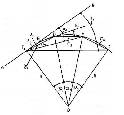
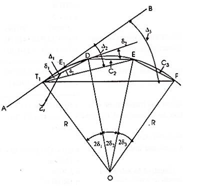
Let T1 and T2 be the tangent points and AB the first tangent to the curve.
D, E, F, etc. =the successive points on the curve,
R = the radius of the curve.
C1, C2, C3 etc. = the lengths of the chords T1D, DE, EF etc., i.e., 1st, 2nd, 3rd chords etc.
δ 1, δ 2, δ 3 etc. = the tangential angles which each of the chords T1 D1, DE, EF, etc., makes with the respective tangents T1, D, E. Etc.
∆1, ∆2, ∆ 3 etc. = the total tangential or deflection angles which the chords T1D, DE, EF, etc. make with the first tangent AB.
Now the chord T1D is approximately equal to arc T1D = C1
∠BT1D = δ1 = ½ ∠T1OD = 2δ1 ∠T1OD = 2δ1

Or C1/R = 2δ1 radians
Or δ1 = C1/R radians
= C1/2R 180/π degrees
= C1/2R 180/π 60 minutes ……..(Eqn. 11.20)
Similarly, δ2 = 1718.9 C2/R ; δ3 = 1718.9 C3/R ; and so on
δn = 1718.9 Cn/R minutes ……..(Eqn. 11.21)
Since each of the chord lengths C2, C3, C4…………. Cn-1 is equal to the length of the full chord, δ2 = δ3 = δ4………….. δ n-1.
The total tangential angle (1) for the first chord (T1D)
= ∠BT1D = δ1
1 = δ1
The total tangential angle (2) for the second chord (DE) = ∠BT1E
But ∠BT1E = ∠BT1D + ∠DT1E
It is well known preposition of geometry that the angle between the tangent and a chord equals the angle which the chord subtends in the opposite segment.
Now ∠DT1E is the angle subtended by the chord DE in the opposite segment, therefore, it is equal to the tangential angle (δ2) between the tangent D and the chard DE
2 = δ1 + δ2 = 1 + δ2
SImilarly, 3 = δ1 + δ2 + δ3 = 2 + d3
n + δ1 + δ2 + δ3 ………..+ δn
= n-1 + δn ………..(Eqn. 11.22)
Check:
The total deflection angle BT1 T2 = n = /2
Where φ is the deflection angle of the curve.
If the degree of die curve (D) is known, the deflection angle for 30 m chord is equal 1/2D degrees, and that for the sub-chord of length C1,
= C1/30 D/2 degrees
δ1 = (C1 D)/60 ; δ2 = δ3 ……δn-1 = D/2;
δn = (Cn D)/60 …………… (Eqn. 11.23)
Q7) Explain procedure of Setting out the Curve
A7)
(i) Locate the tangent factors (T1 and T2) and discover their changes. From those changes, calculate the lengths of first and final sub-chords and the entire deflection angles for all factors at the curve as defined above.
(ii) Set up and stage the theodolite at the primary tangent factor (T1).
(iii) Set the veneer A of the horizontal circle to 0 and direct the telescope to the ranging rod on the intersection factor B and bisect it.
(iv) Loosen the vernier plate and set the veneer A to the primary deflection perspective Δ1, the telescope is accordingly directed alongside T1D. Then alongside this line, degree T1D same in period to the primary sub-chord, accordingly solving the primary factor D at the curve.
(v) Loosen the top clamp and set the vernier A to the second one deflection perspective Δ2, the road of sight is now directed alongside T1E. Hold the 0 quit of the chain at D and swing the alternative quit till the arrow held at that quit is bisected via way of means of the road of sight, accordingly solving the second one factor (E) at the curve.
(vi) Continue the technique till the quit of the curve is reached. The quit factor accordingly positioned ought to coincide with the formerly positioned factor (T2). If not, the space among them is the ultimate error. If it's far inside the permissible limit, simplest the previous couple of pegs can be adjusted; in any other case the curve have to be set out again.
Q8) What is two theodolite method?
A8)
Two-Theodolite Method:
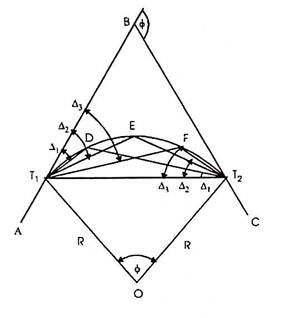
This method is very useful in the absence of chain or tape and also when ground is not favourable for accurate chaining. This is simple and accurate method but requires essentially two instruments and two surveyors to operate upon them, so it is not as commonly used as the method of deflection angles. In this method, the property of circle ‘that the angle between the tangent and the chord equals the angle which that chord subtends in the opposite segment’ is used.
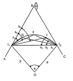
Let D, E, F, etc. be the points on the curve. The angle (Δ1) between the tangent T1B and the chord T1D i.e. ∠BT1 D = ∠T1T2D. Similarly, ∠BT1E = ∆2 = ∠T1T2 E, and ∠BT1F = ∆3 = ∠T1T2F etc. The total deflection angles ∆1, ∆2, ∆3, etc. are calculated from the given data as in the first method (i.e. as in Rankine’s method of deflection angles).
Procedure of setting out the curve:
(i) Set up two theodolites, one at T1 and the other at T2.
(ii) Set vernier of the horizontal circle of each of the theodolites to zero.
(iii) Turn the instrument at T1 to sight the intersection point B and that at T2 to sight T1.
(iv) Set the vernier of each of the instruments to read the first deflection angle Δ1. Now the line of sight of the instrument at T1 is along T1D and that of the instrument at T2 is along T2D. Their point of intersection is the required point on the curve Direct the assistant to move the ranging rod until it is sighted exactly by both the theodolites, thus fixing the point D on the curve.
(v) Then set the vernier of each of the instrument to the second deflection angle Δ2, proceed as before to obtain the second point (E) on the curve.
(vi) Repeat the process until the whole curve is set out.
Obstacles in setting out curves
After reading this article you will learn about the difficulties faced during ranging simple curves.
Case I:
When the point of intersection of the tangents is inaccessible
It so generally takes place that the intersection factor (B) turns into in accessessible because of impediment like lake, river or timber etc. Let AB and BC be the 2 tangents intersection on the factor B, and T1and T2 the tangent factors.
Since the intersections factor (B) is used for measuring the deflection angle (ɸ) and additionally for finding the tangent factors T1 and T2, the field- paintings be organized to degree ɸ and to discover T1and T2without going at B
Producers:
(i) Select two indivisible points M and N suitably on the tangents AB and BC respectively and measure MN accurately.
(ii) Measure the angles AMN (α) and CNM (β) by setting the theodolite at M and N respectively.
Now in BMN,
∠BMN = 180o – α
∠BNM = 180o – β
The deflection angle () = ∠BMN + ∠BNM
= (180o – α) + (180o – β)
= 360o – (α + β)
(iii) Solve the ∆ BMN by the sine rule for the distance BM and BN.

(iv) Calculate the tangent lengths BT1 = BT2 = R tan φ/2
(v) Now the distance MT1 = BT1-BM and NT2 = BT2-BN
(vi) Measure the distance MT1 from M along BA, thus locating the first tangent point T1. Similarly locate T2 by measuring NT2 from N along BC.
When a clear line MN is not available, a traverse is run between M and N to find the length and bearing of the line MN. Then from the known bearings of the tangents and the calculated bearing of the line MN, calculate the angles α and β and proceed as above.
Q9) Explain case 2 in two theodolite method.
A9)
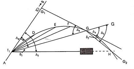
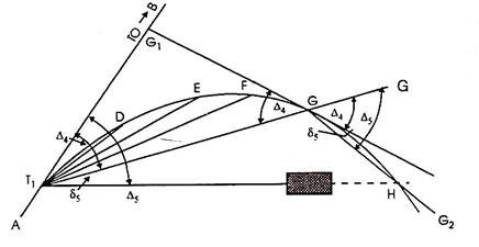
When the complete curve cannot be set out from the starting point due to the obstructed vision:
When the curve is brief and the floor is loose from obstructions like buildings, timber etc., the entire curve may be set out from the primary tangent factor (T1). However it isn't always usually feasible to have quick curves and floor loose from obstacles.
In such instances the device must be installation at one or extra factors alongside the curve. The following manner can be followed in such instances.
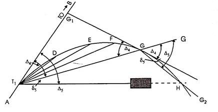
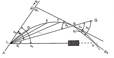
Procedure: Let D, E, F, G, H etc. be the factors at the curve, and G is the remaining factor placed from the device at T1 while it's far determined vital to shift the device. Let deflection perspective for G be ∆4, then deflection perspective for the subsequent factor H must be Δ5.
(i) Shift the device and set it up at G.
(ii) Set the vernier A to zero, take an again sight on T1 and transit the telescope. The line of sight is accordingly directed alongside GG’ i.e. alongside T1 G produced.
(iii) Loose the higher clamp and set the vernier to study the deflection perspective ∆5, accordingly directing the road of sight alongside GH. [By Geometry, ∠G’GH = ∠BT1H. (Please see proof at the end)].
(iv) Locate H via way of means of measuring a distance same to chord period alongside GH.
(v) Then the usage of the equal tabulated deflection angles, keep the starting up of the curve from G as usual.
Q10) What is compound curve?
A10)
Compound Curves
A compound curve is or extra easy curves that have exclusive centers, bend with inside the equal direction, lie at the equal facet in their not unusual place tangent, and hook up with shape a non-stop arc.
The factor in which the 2 curves connect (namely, the factor at which the PT of the primary curve equals the PC of the second one curve) is called the factor of compound curvature (PCC).
Since their tangent lengths vary, compound curves healthy the topography an awful lot higher than easy curves.
These curves effortlessly adapt to mountainous terrain or regions reduce with the aid of using large, winding rivers.
However, because compound curves are extra unsafe than easy curves, they need to in no way be used in which an easy curve will do.
Elements of compound Curves
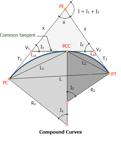
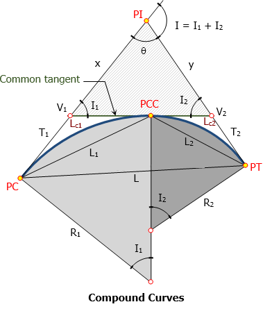
A compound curve consists of two (or more) circular curves between two main tangents joined at point of compound curve (PCC). Curve at PC is designated as 1 (R1, L1, T1, etc) and curve at PT is designated as 2 (R2, L2, T2, etc).
Elements of compound curve
- PC = point of curvature
- PT = point of tangency
- PI = point of intersection
- PCC = point of compound curve
- T1 = length of tangent of the first curve
- T2 = length of tangent of the second curve
- V1 = vertex of the first curve
- V2 = vertex of the second curve
- I1 = central angle of the first curve
- I2 = central angle of the second curve
- I = angle of intersection = I1 + I2
- Lc1 = length of first curve
- Lc2 = length of second curve
- L1 = length of first chord
- L2 = length of second chord
- L = length of long chord from PC to PT
- T1 + T2 = length of common tangent measured from V1 to V2
- θ = 180° - I
- x and y can be found from triangle V1-V2-PI.
- L can be found from triangle PC-PCC-PT
Q11) Explain setting out curves for compound curve in detail.
A11)
Setting out the curve
Step 1: Locate the tangent factor T, through measuring returned the whole tangent period (Tt) alongside the returned tangent, from the factor of intersection V. Likewise, find the tangent factor T' through measuring alongside the ahead tangent the gap Tt from V. Setting out of the transition curve:
Step 2: Set a theodolite over the factor T. Set the vernier A to 0, and clamp the top plate.
Step 3: Direct the road of sight of theodolite to the intersection factor V, and clamp the decrease plate.
Step 4: Release the top plate. Set the vernier A to the primary deflection perspective (a1). The line of sight now factors closer to the primary peg at the transition curve.
Step 5: With the 0 of the tape pinned at T and an arrow saved on the mark similar to the primary period of the chord, the assistant will swing the tape until the arrow is bisected through the road of sight. Fix the primary peg on the arrow factor.
Step 6: Set the vernier A on the second one deflection perspective (a2) to direct the road of sight to the second one peg.
Step 7: With the 0 of the tape pinned at T, and retaining an arrow on the mark similar to the whole period of the primary and 2d chords, the assistant will swing an arc until the arrow is bisected through the road of sight. Fix the second one peg on the arrow factor. It must be remembered that the gap is measured from the factor T and now no longer from the preceding factor.
Step 8: repeat steps (6) and (7) until the closing factor C at the transition curve is reached. Setting out of the round curve:
Step 9 : For starting up the round curve CC', shift the theodolite to junction factor C. Orient the theodolite as regards to the not unusual place tangent CC1 through directing the road of sight closer to CT with the vernier.
Step 10: Plunge the telescope. The line of sight is now directed alongside the tangent C1C produced. The deflection angles D1, D2, etc. were calculated as regards to the tangent C1C produced at C
The line of sight is now successfully oriented, and the studying of the vernier A is 0.
Step 11 : Set the vernier A to the primary deflection perspective D1, and find the primary peg at the round curve at a distance of c' from C, in which c' is period of the primary sub-chord.
Step 12: Likewise, find the second one peg at the round curve at the gap c identical to the ordinary chord from the primary peg with the deflection perspective D2 at C.
Step 13: Continue the above procedure until the junction factor C' is reached. Step 14: Set out the transition curve T'C' from T' the use of the identical method as that for the transition curve TC.
Q12) Explain reverse curve in detail.
A12)
Reverse Curves
An opposite curve consists of or greater easy curves handing over contrary directions. Their factors of intersection lie on contrary ends of a not unusual place tangent, and the PT of the primary curve is coincident with the PC of the second.
This factor is known as the factor of opposite curvature (PRC). Reverse curves are beneficial whilst laying out such things as pipelines, flumes, and levees. The surveyor may additionally use them on low-pace roads and railroads.
They can't be used on high-pace roads or railroads due to the fact that they can't be nicely super elevated on the PRC. They are every so often used on canals, however most effective with severe caution, due to the fact that they make the canal hard to navigate and make contributions to erosion.
The inexperienced device is an unmarried tangent round arc. Even eleven though it's far an especially sharp curve, it takes up the maximum space (to take in much less space, it might want to be even sharper).
Its number one shortcomings are the tangent-curve-tangent transitions and centrifugal pressure situation requiring a decrease velocity and better super elevation.
The crimson device is a five-middle compound curve the usage of consecutive curves of various radii. The idea at the back of this utility became mentioned in Chapter D.
While higher than the unmarried curve and taking on much less space, it may nevertheless be tricky on the curve-curve transitions for the reason that forces can extrude considerably until speeds are reduced.
The blue device is a spiraled horizontal curve: a front spiral right into a round arc into a go out spiral. In this example, that is a symmetric device with front and go out spirals reflect pictures of every other, despite the fact that that need not be the case.
Not handiest does this curve device offer the smoothest velocity and path changes, it's far the maximum cushy and takes up the least space.
Elements of reverse Curves
Reversed curve, though pleasing to the eye, would bring discomfort to motorist running at design speed. The instant change in direction at the PRC brought some safety problems. Despite this fact, reversed curves are being used with great success on park roads, formal paths, waterway channels, and the like.
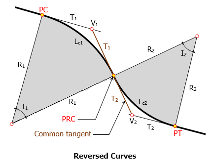
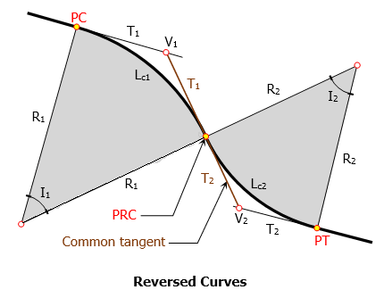
Elements of Reversed Curve
- PC = point of curvature
- PT = point of tangency
- PRC = point of reversed curvature
- T1 = length of tangent of the first curve
- T2 = length of tangent of the second curve
- V1 = vertex of the first curve
- V2 = vertex of the second curve
- I1 = central angle of the first curve
- I2 = central angle of the second curve
- Lc1 = length of first curve
- Lc2 = length of second curve
- L1 = length of first chord
- L2 = length of second chord
- T1 + T2 = length of common tangent measured from V1 to V2
Q13) Explain setting out the curve for reverse curve in detail.
A13)
Setting out the curve
An opposite curve includes round arcs of same or distinct radii returning contrary guidelines with a general tangent on the junction of the arcs.
The junction factor is said to own opposite curvature,
The opposite curve is moreover known as a serpentine curve. Reverse curves are normally wont to attach parallel roads or railway strains, or whilst strains intersect at a genuinely small angle.
These curves are well matched for railway sidings, metropolis roads, etc. But they should be averted as a ways as viable for essential tracks or highways for the following reasons:
1. Super elevation cannot be supplied on the reason of opposite curvature.
2. A snappy converting of course could be risky for a car.
3. A snappy converting of cant reasons soreness to passengers.
Reverse curves are normally short.
And for this reason they may be began out through the chain and tape method.
Step 1: Locate the tangent factor T, through measuring returned the whole tangent period (Tt) alongside the returned tangent, from the factor of intersection V. Likewise, find the tangent factor T' through measuring alongside the ahead tangent the gap Tt from V. Setting out of the transition curve :
Step 2: Set a theodolite over the factor T. Set the vernier A to 0, and clamp the top plate.
Step 3: Direct the road of sight of theodolite to the intersection factor V, and clamp the decrease plate.
Step 4: Release the top plate. Set the vernier A to the primary deflection perspective (a1). The line of sight now factors closer to the primary peg at the transition curve.
Step 5: With the 0 of the tape pinned at T and an arrow saved on the mark similar to the primary period of the chord, the assistant will swing the tape until the arrow is bisected through the road of sight. Fix the primary peg on the arrow factor.
Step 6: Set the vernier A on the second one deflection perspective (a2) to direct the road of sight to the second one peg.
Step 7: With the 0 of the tape pinned at T, and retaining an arrow on the mark similar to the whole period of the primary and 2d chords, the assistant will swing an arc until the arrow is bisected through the road of sight. Fix the second one peg on the arrow factor. It must be remembered that the gap is measured from the factor T and now no longer from the preceding factor.
Step 8: repeat steps (6) and (7) until the closing factor C at the transition curve is reached. Setting out of the round curve:
Step 9 : For starting up the round curve CC', shift the theodolite to junction factor C. Orient the theodolite as regards to the not unusual place tangent CC1 through directing the road of sight closer to CT with the vernier.
Step 10: Plunge the telescope. The line of sight is now directed alongside the tangent C1C produced. The deflection angles D1, D2, etc. were calculated as regards to the tangent C1C produced at C
The line of sight is now successfully oriented, and the studying of the vernier A is 0.
Step 11 : Set the vernier A to the primary deflection perspective D1, and find the primary peg at the round curve at a distance of c' from C, in which c' is period of the primary sub-chord.
Step 12: Likewise, find the second one peg at the round curve at the gap c identical to the ordinary chord from the primary peg with the deflection perspective D2 at C.
Step 13: Continue the above procedure until the junction factor C' is reached. Step 14: Set out the transition curve T'C' from T' the use of the identical method as that for the transition curve TC.
Q14) What is vertical curve?
A14)
Vertical Curves
Vertical Curves are the second one of the 2 essential transition factors in geometric layout for highways, the primary being Horizontal Curves. A vertical curve gives a transition among sloped roadways, permitting an automobile to barter the elevation fee alternate at a slow fee as opposed to a pointy cut.
The layout of the curve is depending on the meant layout velocity for the roadway, in addition to different elements inclusive of drainage, slope, appropriate fee of alternate, and friction.
These curves are parabolic and are assigned stationing primarily based totally on a horizontal axis.
Elements of vertical curves
Vertical curves provide a transition between two sloped roadways, allowing vehicles to negotiate the elevation rate change gradually rather than at sharp cut.
The design of the curve is dependent on:
- The intended design speed for the roadway
- Drainage
- Slope
- Acceptable rate of change
- Friction
These curves are parabolic and are assigned stationing based on a horizontal axis.
Two types of vertical curves:
- Sag Curves
Used where the change in grade is positive, such as valleys defined points:
- PVC (Point of Vertical Curve) – start point of the curve
- PVI (Point of Vertical Intersection)
- PVT (Point of Vertical Tangency) – end point of the curve
2. Crest Curves
Used when the change in grade is negative, such as hills3 defined points:
- PVC
- PVI
- PVT
The roadway grade that approaches a Point of Vertical Curve (PVC) is g1, measured in ft/ft (or m/m)
The roadway grade that leaves a PVT is g2, measured in ft/ft (or m/m)
Types
- Summit curve: When two grades meet at the summit and the curve will have convexity upwards, the curve is simply referred as summit curve.
- Valley (Sag) curve: When two grades meet at the valley (sag) and the curve will have convexity downwards, the curve is simply referred as the valley (sag) curve.
Tangent correction
The format of the curve is relying at the supposed format pace for the roadway, similarly to distinct factors such as drainage, slope, suitable charge of alternate, and friction Vertical curves offer a transition among sloped roadways, permitting cars to barter the elevation fee extrude step by step as opposed to a sharp cut.
The format of the curve is relying at the supposed format pace for the roadway, similarly to distinct factors such as drainage, slope, suitable charge of alternate, and friction
Q15) Explain location of highest or lowest point in detail.
A15)
Location of highest or lowest point
High or Low Point
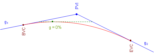
When asked where a curve's highest, or lowest, point is, most people assume it is at the middle of the curve. This is true only under a specific condition. The high or low point occurs where the curve changes direction vertically. This happens where the curve tangent has a 0% grade, Figure.
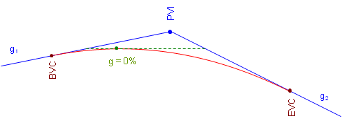
a. Crest Curve

b. Sag Curve
Figure. High and Low Point Conditions
On a crest curve, the tangent grade begins at g1 and deceases uniformly (by k). As long as the grade is positive, the curve elevation keeps increasing. At 0%, the curve reaches its maximum elevation and after that the grade decreases, causing curve elevations to drop.
The opposite is true for a sag curve. As the grade decreases, while it is still negative curve elevations decrease. When the grade is 0%, the elevation decrease stops and as the tangent slope increases so do curve elevations.
The only condition under which the high or low point occurs at the center of the curve is when incoming and outgoing grades are numerically equal but have opposite mathematical signs (eg, +2% into -2%, -3% into +3%).
The distance from the BVC to the high/low point, dp in Figure, is determined from Equation B-10:
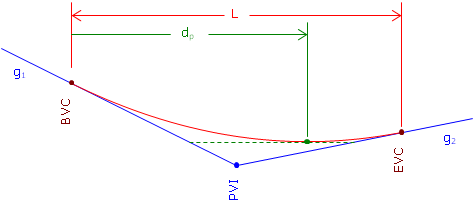
Figure. Distance to High/Low Point
 Equation B-10
The high/low point elevation can be computed by substituting dp in Equation B-7.
In order for Equation B-8 to return a value that makes sense, the grades must have opposite mathematical signs. Consider a +3.00% grade connected to a +1.00% grade with a 500.00 ft long curve. Using Equation B-10 the distance from the BVC to the high/low point is:

The distance exceeds the curve length. What's up with that? Let's sketch it, Figure.
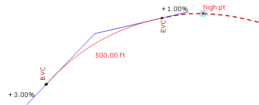
Figure. High Point After the EVC
Remember, we are using only part of the parabolic curve. 7.5000 stations is the distance to the curve's highest point, it's just on that part of the curve we're not using. Our curve's actual highest point is at the EVC.
Similarly for a +0.50% grade connected to a +2.00% with a 400.00 ft curve:

This means the high/low point occurs before the BVC, Figure.
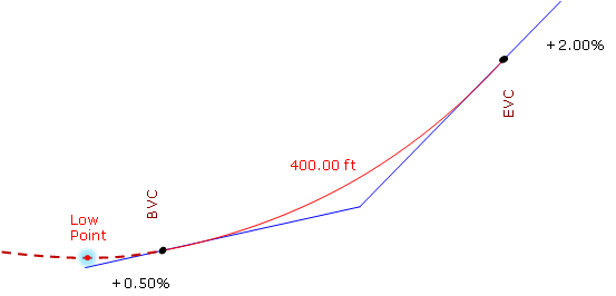
Figure. Low Point Before the BVC
The lowest point for this curve is at the BVC.
Unit - 2
Simple, Compound, Reverse Curves and Vertical Curves
Q1) What is simple curve?
A1)
Simple Curves
Curves are everyday bends furnished with inside the strains of verbal exchange like roads, railways etc. and additionally in canals to result in the sluggish alternate of course.
They also are used with inside the vertical aircraft in any respect adjustments of grade to keep away from the abrupt alternate of grade on the apex.
Curves furnished with inside the horizontal aircraft to have the sluggish alternate in course are referred to as Horizontal curves, while the ones furnished with inside the vertical aircraft to gain the sluggish alternate in grade are referred to as vertical curves.
Curves are laid out at the floor alongside the center line of the work. They can be round or parabolic.
A simple curve consists of a single arc of a circle connecting two straights. It has radius of the same magnitude throughout. In fig. T1 D T2 is the simple curve with T1O as its radius.
Q2) What are the elements if simple curve?
A2)
Elements of simple curve:
Figure shows the elements of a simple curve. They are described as follows, and their abbreviations are given in parentheses.
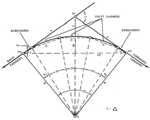
Figure. Elements of a simple curve
Point of Intersection (PI)
The factor of intersection marks the factor in which the lower back and ahead tangents intersect. The surveyor shows it as one of the stations at the initial traverse.
Intersecting Angle (I)
The intersecting attitude is the deflection attitude on the PI.
Radius (R)
The radius is the radius of the circle of which the curve is an arc.
Point of Curvature (PC)
The factor of curvature is the factor in which the round curve begins. The lower back tangent is tangent to the curve at this factor.
Point of Tangency (PT)
The factor of tangency is the stop of the curve. The ahead tangent is tangent to the curve at this factor.
Length of Curve (L)
The period of curve is the gap from the PC to the PT measured alongside the curve.
Tangent Distance (T)
The tangent distance is the gap alongside the tangents from the PI to the PC or PT. These distances are identical on an easy curve.
Central Angle (Δ)
The valuable attitude is the attitude fashioned through radii drawn from the middle of the circle (0) to the PC and PT. The valuable attitude is identical in fee to the I attitude.
Long Chord (LC)
The lengthy chord is the chord from the PC to the PT.
External Distance (E)
The outside distance is the gap from the PI to the midpoint of the curve. The outside distance bisects the indoors attitude on the PI.
Middle Ordinate (M)
The center ordinate is the gap from the midpoint of the curve to the midpoint of the lengthy chord. The extension of the center ordinate bisects the valuable attitude.
Degree of Curve (D)
The diploma of curve defines the “sharpness” or “flatness” of the curve (determine 3). There are definitions usually in use for diploma of curve, the arc definition and the chord definition.
Arc definition.
The arc definition states that the diploma of curve (D) is the attitude fashioned through radii drawn from the middle of the circle (factor O, determine 3) to the ends of an arc one hundred ft. Or 30.forty eight meters lengthy. In this definition, the diploma of curve and radius are inversely proportional the use of the subsequent formula:

Circumference = 2 π Radius
π = 3.141592654
Chords
On curves with lengthy radii, it's miles impractical to stake the curve via way of means of finding the middle of the circle and swinging the arc with a tape.
The surveyor lays those curves out via way of means of staking the ends of a chain of chords (parent 4). Since the ends of the chords lie at the circumference of the curve, the surveyor defines the arc with inside the field.
The duration of the chords varies with the diploma of curve. To lessen the discrepancy among the arc distance and chord distance, the surveyor makes use of the subsequent chord lengths:
The chord lengths above are the most distances wherein the discrepancy among the arc duration and chord duration will fall with inside the allowable blunders for taping, that's 0. 02 foot in keeping with one hundred ft. On maximum creation surveys.
Degree of Curve | Radius Feet | Radius Meters | Chord Feet | Lengths Meters |
From 1 - 3 | 5,730 – 1,910 | 1,745 - 585 | 100 | 30.0 |
3 - 8 | 1,910 - 720 | 585 - 220 | 50 | 15.0 |
8 - 16 | 720 - 360 | 220 - 110 | 25 | 7.5 |
Over 16 | 360 - 150 | 110 - 45 | 10 | 3 |
Deflection Angles
The deflection angles are the angles among a tangent and the ends of the chords from the PC. The surveyor makes use of them to discover the path wherein the chords are to be laid out. The overall of the deflection angles is continually same to 1 1/2 of the I angle. This overall serves as a test at the computed deflection angles.
Q3) What are the methods of curve ranging?
A3)
Methods of curve ranging
The strategies of starting off curves can be divided in classes in line with the tool hired.
1. Linear or chain and tape method: - Linear strategies are the ones in which the curve is about out with chain and tape only.
2. Angular or instrumental method: - instrumental strategies are the ones in which theodolite without or with a series is hired to set out curve.
1. Linear or chain and tape method
The following are the methods of setting out simple circular curves by linear methods and by the use of chain and tape:
1. By ordinates from the Long chord
2. By Successive Bisection of Arcs.
3. By Offsets from the Tangents.
4. By Offsets from Chords Produced.
1. By Ordinates from the Long Chord:
Let T1T2=L= the length of the Long chord
ED= O0= the offset at mid-point (e) of the long chord (the versed sine)
PQ=Ox= the offset at distance x from E
Draw QQ1 parallel to T1 T2 meeting DE at Q1
Join OQ cutting T1T2 in P1
From the OQQ1 , OQ2 = QQ12 + OQ12
But OQ = R ; OQ1 = x
And OQ1 = OE + EQ1 = (R – Q3) + Ox
R2 = x2 {(R – O0) + O0}2
Or (R – O0) + Ox = (R2 – x2)
Hence Ox = (R2 – x2)-(R - O)
(Exact) … …(Eqn. 11.10)
Where O0 = ED = OD – OE
= R -  … …(Eqn. 11. 10, a)
When the radius of the curve is large as compared with the length of the long chord, the offset may be equated by the approximate formula which is derived as follows:
Here Ox is assumed to be equal to the radial ordinate QP1.
QP 2R = T1P PT2
Or QP1 = (T1P PT2)/2R
Now T1P = x, and PT2 = L – x
Qx = x(L – x)/2R (approximate) …… ……..(Eqn. 11.11)
2. By Successive Bisections of Arcs:
It is also known as Versing Method. Join T1 T2 and bisect it at E. Set out the offset ED the versed since equal to:
R(1 – cos /2, thus fixing the point Don the curve
Join T1D and DT2 and bisect them at F and G respectively. Then set outsets FH and GK at F and G each equal to R(1 – cos /4) thus fixing two more points H and K on the curve. Then each of the offsets to be set out at mid points of the chords T1H, HD, DK and KT2 is equal to R(1 – cos /8).By repeating this process, set out as many point as are required.
This method is suitable where the ground outside the curve is not favourable to the tangents.
3. By Offsets from the Tangents:
The offsets may be either radial or perpendicular to the tangents.
(a) By Radial Offsets:
Let Ox = PP1 = the radial offset at P at a distance of x from T1 along the tangent AB
PP1 = OP – OP1 , where OP =  and OP1 = R
Ox =  - R (exact) ………(Eqn . 11. 12)
When the radius is large, the offsets may be calculated by the approximate formula, which may be derived as under:
PT12 = PP1 (2R + PP1)
i.e. x2 = Ox (2R + Ox ) = 2ROx + Ox2
Since Ox2 is very small as compared with 2R, it may be neglected.
x2 = 2R.Ox
Or Ox = x2/2R (approximate) ……(Eqn. 11.13)
(b) By Offsets perpendicular to the Tangents:
Let Ox = PP1 = the perpendicular offset at P at a distance of x from T1 along the tangent AB.
Draw P1P2 parallel to BT1, meeting OT1 at P2
Then P1P2 = PT1 = x; T1P2 = PP1 = Ox.
Now T1P2 = OT1 – OP2
Where OT1 = R, and OP2 = 
Ox = R -  (exact) …..(Eqn. 11.14)
The approximate formula may be obtained similarly as in (a) above,
Ox = x2/2R (approximate) ………(Eqn. 11.5)
Q4) Explain procedure of setting out the curve.
A4)
(i) Locate the tangent points T1 and T2.
(ii) Measure equal distances, say 15 or 30 m along the tangent from T1.
(iii) Set out the offsets calculated by any of the above methods at each distance, thus obtaining the required points on the curve.
(iv) Continue the process until the apex of the curve is reached.
(v) Set out the other half of the curve from the second tangent.
This method is suitable for setting out sharp curves where the ground outside the curve is favorable for chaining.
By Offsets from Chords Produced:
Let AB = the first tangent; T1 = the first tangent point E, F, G etc on the successive points on the curve T1E = T1E1 = C1 = the first chords.
EF, FG, etc. = the successive chords of length C2, C3 etc., each being equal to the full chord.
∠ BT1E = α in radians = the angle between the tangents BT1 and the first chord T1E.
E1E = O1 = the offset from the tangent BT1
E2F = O2 = the offset from the chord T1E produced.
Produce T1E to E2 such tharEE2 = C2. Draw the tangent DEF1 at E meeting the first tangent at D and E2F at F1.
∠BT1E= α in the radians= the angle between the tangents BT1and the first chord T1E.
E1E=O1= the offset from the tangent BT1
E2F=O2= the offset from the chord T1E produced.
Produce T1E to E2 such that EE2= C2.Draw the tangent DEF1at E meeting the first tangent at D and E2Fat F1.
The formula for the offsets may be derived a under:
∠ BT1E=x
∠T1OE=2x
The angle subtended by any chord at the center is twice the angle between the chord and the tangent

But arc T1E is approximately equal to chord T1E = C
C1/R = 2α
Or α = C1/2R
Also 
But arc EE is approximately equal to chord E1E = =O1
O1 = C1 α
Putting here the value of α as calculated above.
O1 = C1 C1/2R = C12/2R ………….(Eqn. 11.16)
O2 = offset E2F = E2F1 + F1F
To find out F2F1, consider the two triangles TEE1 and EF1E2
∠E2EF1 = ∠DET1 (vertically opposite angles):
∠DET1 = ∠DT1E, since DT1 = DE, both being tangents to the circle.
∠E1EF1 = ∠DET1 = ∠DT1E
Both the s being nearly isosceles, may be taken as approximately similar,

∠α
i.e., 
Or E2F1 = (C2 O1)/C2
= C2/C1 C12/2R = (C1C2)/2R
F1F being the offset from the tangent at E, is equal to
EF2/2R = C22/2R
The second offset, O2 = (C1C2)/2R + C22/2R,
 …….(Eqn. 11.17)
Similarly the third offset, O3 = 
Since C2 = C3 = C1 ……….etc,
O3 = C22/R ……………(Eqn. 11. 18)
Each of the remaining offsets O4,O5 etc expect the last one (On) is equal to O3. Since the length of the last chord is usually less than the length of the chord, the last offset,

Q5) Explain procedure of Setting out the Curve
A5)
(i) Locate the tangent points (T1 and T2) and find out their changes. From these changes, calculate lengths of first and last sub-chords and find out the offsets by using the equations 11.16 to 11.19.
(ii) Mark a point E1 along the first tangent T1B such that T1E1 equals the length of the first sub-chord.
(iii) With the zero end of the chain (or tape) at T1 and radius = T1E1, swing an arc E1E and cut off E1E = O1, thus fixing the first point E on the curve.
(iv) Pull the chain forward in the direction of T1E produced until the length EE2 becomes equal to the second chord C2.
(v) Hold the zero end of the chain at E. And radius = C2, swing an arc E2F and cut off E2F = O2, thus fixing the second point F on the curve.
(vi) Continue the process until the end of the curve is reached. The last point fixed in this way should coincide with the previously located point T2. If not, find the closing error. If it is large i.e., more than 2 m, the whole curve are moved sideways by an amount proportional to the square of their distances from the tangent point T1. The closing error is thus distributed among all the points.
This method is very commonly used for setting out road curves.
Q6) How deflection angles are calculated?
A6)
The deflection angles are calculated as follows:
Let T1 and T2 be the tangent points and AB the first tangent to the curve.
D, E, F, etc. =the successive points on the curve,
R = the radius of the curve.
C1, C2, C3 etc. = the lengths of the chords T1D, DE, EF etc., i.e., 1st, 2nd, 3rd chords etc.
δ 1, δ 2, δ 3 etc. = the tangential angles which each of the chords T1 D1, DE, EF, etc., makes with the respective tangents T1, D, E. Etc.
∆1, ∆2, ∆ 3 etc. = the total tangential or deflection angles which the chords T1D, DE, EF, etc. make with the first tangent AB.
Now the chord T1D is approximately equal to arc T1D = C1
∠BT1D = δ1 = ½ ∠T1OD = 2δ1 ∠T1OD = 2δ1

Or C1/R = 2δ1 radians
Or δ1 = C1/R radians
= C1/2R 180/π degrees
= C1/2R 180/π 60 minutes ……..(Eqn. 11.20)
Similarly, δ2 = 1718.9 C2/R ; δ3 = 1718.9 C3/R ; and so on
δn = 1718.9 Cn/R minutes ……..(Eqn. 11.21)
Since each of the chord lengths C2, C3, C4…………. Cn-1 is equal to the length of the full chord, δ2 = δ3 = δ4………….. δ n-1.
The total tangential angle (1) for the first chord (T1D)
= ∠BT1D = δ1
1 = δ1
The total tangential angle (2) for the second chord (DE) = ∠BT1E
But ∠BT1E = ∠BT1D + ∠DT1E
It is well known preposition of geometry that the angle between the tangent and a chord equals the angle which the chord subtends in the opposite segment.
Now ∠DT1E is the angle subtended by the chord DE in the opposite segment, therefore, it is equal to the tangential angle (δ2) between the tangent D and the chard DE
2 = δ1 + δ2 = 1 + δ2
SImilarly, 3 = δ1 + δ2 + δ3 = 2 + d3
n + δ1 + δ2 + δ3 ………..+ δn
= n-1 + δn ………..(Eqn. 11.22)
Check:
The total deflection angle BT1 T2 = n = /2
Where φ is the deflection angle of the curve.
If the degree of die curve (D) is known, the deflection angle for 30 m chord is equal 1/2D degrees, and that for the sub-chord of length C1,
= C1/30 D/2 degrees
δ1 = (C1 D)/60 ; δ2 = δ3 ……δn-1 = D/2;
δn = (Cn D)/60 …………… (Eqn. 11.23)
Q7) Explain procedure of Setting out the Curve
A7)
(i) Locate the tangent factors (T1 and T2) and discover their changes. From those changes, calculate the lengths of first and final sub-chords and the entire deflection angles for all factors at the curve as defined above.
(ii) Set up and stage the theodolite at the primary tangent factor (T1).
(iii) Set the veneer A of the horizontal circle to 0 and direct the telescope to the ranging rod on the intersection factor B and bisect it.
(iv) Loosen the vernier plate and set the veneer A to the primary deflection perspective Δ1, the telescope is accordingly directed alongside T1D. Then alongside this line, degree T1D same in period to the primary sub-chord, accordingly solving the primary factor D at the curve.
(v) Loosen the top clamp and set the vernier A to the second one deflection perspective Δ2, the road of sight is now directed alongside T1E. Hold the 0 quit of the chain at D and swing the alternative quit till the arrow held at that quit is bisected via way of means of the road of sight, accordingly solving the second one factor (E) at the curve.
(vi) Continue the technique till the quit of the curve is reached. The quit factor accordingly positioned ought to coincide with the formerly positioned factor (T2). If not, the space among them is the ultimate error. If it's far inside the permissible limit, simplest the previous couple of pegs can be adjusted; in any other case the curve have to be set out again.
Q8) What is two theodolite method?
A8)
Two-Theodolite Method:
This method is very useful in the absence of chain or tape and also when ground is not favourable for accurate chaining. This is simple and accurate method but requires essentially two instruments and two surveyors to operate upon them, so it is not as commonly used as the method of deflection angles. In this method, the property of circle ‘that the angle between the tangent and the chord equals the angle which that chord subtends in the opposite segment’ is used.
Let D, E, F, etc. be the points on the curve. The angle (Δ1) between the tangent T1B and the chord T1D i.e. ∠BT1 D = ∠T1T2D. Similarly, ∠BT1E = ∆2 = ∠T1T2 E, and ∠BT1F = ∆3 = ∠T1T2F etc. The total deflection angles ∆1, ∆2, ∆3, etc. are calculated from the given data as in the first method (i.e. as in Rankine’s method of deflection angles).
Procedure of setting out the curve:
(i) Set up two theodolites, one at T1 and the other at T2.
(ii) Set vernier of the horizontal circle of each of the theodolites to zero.
(iii) Turn the instrument at T1 to sight the intersection point B and that at T2 to sight T1.
(iv) Set the vernier of each of the instruments to read the first deflection angle Δ1. Now the line of sight of the instrument at T1 is along T1D and that of the instrument at T2 is along T2D. Their point of intersection is the required point on the curve Direct the assistant to move the ranging rod until it is sighted exactly by both the theodolites, thus fixing the point D on the curve.
(v) Then set the vernier of each of the instrument to the second deflection angle Δ2, proceed as before to obtain the second point (E) on the curve.
(vi) Repeat the process until the whole curve is set out.
Obstacles in setting out curves
After reading this article you will learn about the difficulties faced during ranging simple curves.
Case I:
When the point of intersection of the tangents is inaccessible
It so generally takes place that the intersection factor (B) turns into in accessessible because of impediment like lake, river or timber etc. Let AB and BC be the 2 tangents intersection on the factor B, and T1and T2 the tangent factors.
Since the intersections factor (B) is used for measuring the deflection angle (ɸ) and additionally for finding the tangent factors T1 and T2, the field- paintings be organized to degree ɸ and to discover T1and T2without going at B
Producers:
(i) Select two indivisible points M and N suitably on the tangents AB and BC respectively and measure MN accurately.
(ii) Measure the angles AMN (α) and CNM (β) by setting the theodolite at M and N respectively.
Now in BMN,
∠BMN = 180o – α
∠BNM = 180o – β
The deflection angle () = ∠BMN + ∠BNM
= (180o – α) + (180o – β)
= 360o – (α + β)
(iii) Solve the ∆ BMN by the sine rule for the distance BM and BN.

(iv) Calculate the tangent lengths BT1 = BT2 = R tan φ/2
(v) Now the distance MT1 = BT1-BM and NT2 = BT2-BN
(vi) Measure the distance MT1 from M along BA, thus locating the first tangent point T1. Similarly locate T2 by measuring NT2 from N along BC.
When a clear line MN is not available, a traverse is run between M and N to find the length and bearing of the line MN. Then from the known bearings of the tangents and the calculated bearing of the line MN, calculate the angles α and β and proceed as above.
Q9) Explain case 2 in two theodolite method.
A9)
When the complete curve cannot be set out from the starting point due to the obstructed vision:
When the curve is brief and the floor is loose from obstructions like buildings, timber etc., the entire curve may be set out from the primary tangent factor (T1). However it isn't always usually feasible to have quick curves and floor loose from obstacles.
In such instances the device must be installation at one or extra factors alongside the curve. The following manner can be followed in such instances.
Procedure: Let D, E, F, G, H etc. be the factors at the curve, and G is the remaining factor placed from the device at T1 while it's far determined vital to shift the device. Let deflection perspective for G be ∆4, then deflection perspective for the subsequent factor H must be Δ5.
(i) Shift the device and set it up at G.
(ii) Set the vernier A to zero, take an again sight on T1 and transit the telescope. The line of sight is accordingly directed alongside GG’ i.e. alongside T1 G produced.
(iii) Loose the higher clamp and set the vernier to study the deflection perspective ∆5, accordingly directing the road of sight alongside GH. [By Geometry, ∠G’GH = ∠BT1H. (Please see proof at the end)].
(iv) Locate H via way of means of measuring a distance same to chord period alongside GH.
(v) Then the usage of the equal tabulated deflection angles, keep the starting up of the curve from G as usual.
Q10) What is compound curve?
A10)
Compound Curves
A compound curve is or extra easy curves that have exclusive centers, bend with inside the equal direction, lie at the equal facet in their not unusual place tangent, and hook up with shape a non-stop arc.
The factor in which the 2 curves connect (namely, the factor at which the PT of the primary curve equals the PC of the second one curve) is called the factor of compound curvature (PCC).
Since their tangent lengths vary, compound curves healthy the topography an awful lot higher than easy curves.
These curves effortlessly adapt to mountainous terrain or regions reduce with the aid of using large, winding rivers.
However, because compound curves are extra unsafe than easy curves, they need to in no way be used in which an easy curve will do.
Elements of compound Curves
A compound curve consists of two (or more) circular curves between two main tangents joined at point of compound curve (PCC). Curve at PC is designated as 1 (R1, L1, T1, etc) and curve at PT is designated as 2 (R2, L2, T2, etc).
Elements of compound curve
- PC = point of curvature
- PT = point of tangency
- PI = point of intersection
- PCC = point of compound curve
- T1 = length of tangent of the first curve
- T2 = length of tangent of the second curve
- V1 = vertex of the first curve
- V2 = vertex of the second curve
- I1 = central angle of the first curve
- I2 = central angle of the second curve
- I = angle of intersection = I1 + I2
- Lc1 = length of first curve
- Lc2 = length of second curve
- L1 = length of first chord
- L2 = length of second chord
- L = length of long chord from PC to PT
- T1 + T2 = length of common tangent measured from V1 to V2
- θ = 180° - I
- x and y can be found from triangle V1-V2-PI.
- L can be found from triangle PC-PCC-PT
Q11) Explain setting out curves for compound curve in detail.
A11)
Setting out the curve
Step 1: Locate the tangent factor T, through measuring returned the whole tangent period (Tt) alongside the returned tangent, from the factor of intersection V. Likewise, find the tangent factor T' through measuring alongside the ahead tangent the gap Tt from V. Setting out of the transition curve:
Step 2: Set a theodolite over the factor T. Set the vernier A to 0, and clamp the top plate.
Step 3: Direct the road of sight of theodolite to the intersection factor V, and clamp the decrease plate.
Step 4: Release the top plate. Set the vernier A to the primary deflection perspective (a1). The line of sight now factors closer to the primary peg at the transition curve.
Step 5: With the 0 of the tape pinned at T and an arrow saved on the mark similar to the primary period of the chord, the assistant will swing the tape until the arrow is bisected through the road of sight. Fix the primary peg on the arrow factor.
Step 6: Set the vernier A on the second one deflection perspective (a2) to direct the road of sight to the second one peg.
Step 7: With the 0 of the tape pinned at T, and retaining an arrow on the mark similar to the whole period of the primary and 2d chords, the assistant will swing an arc until the arrow is bisected through the road of sight. Fix the second one peg on the arrow factor. It must be remembered that the gap is measured from the factor T and now no longer from the preceding factor.
Step 8: repeat steps (6) and (7) until the closing factor C at the transition curve is reached. Setting out of the round curve:
Step 9 : For starting up the round curve CC', shift the theodolite to junction factor C. Orient the theodolite as regards to the not unusual place tangent CC1 through directing the road of sight closer to CT with the vernier.
Step 10: Plunge the telescope. The line of sight is now directed alongside the tangent C1C produced. The deflection angles D1, D2, etc. were calculated as regards to the tangent C1C produced at C
The line of sight is now successfully oriented, and the studying of the vernier A is 0.
Step 11 : Set the vernier A to the primary deflection perspective D1, and find the primary peg at the round curve at a distance of c' from C, in which c' is period of the primary sub-chord.
Step 12: Likewise, find the second one peg at the round curve at the gap c identical to the ordinary chord from the primary peg with the deflection perspective D2 at C.
Step 13: Continue the above procedure until the junction factor C' is reached. Step 14: Set out the transition curve T'C' from T' the use of the identical method as that for the transition curve TC.
Q12) Explain reverse curve in detail.
A12)
Reverse Curves
An opposite curve consists of or greater easy curves handing over contrary directions. Their factors of intersection lie on contrary ends of a not unusual place tangent, and the PT of the primary curve is coincident with the PC of the second.
This factor is known as the factor of opposite curvature (PRC). Reverse curves are beneficial whilst laying out such things as pipelines, flumes, and levees. The surveyor may additionally use them on low-pace roads and railroads.
They can't be used on high-pace roads or railroads due to the fact that they can't be nicely super elevated on the PRC. They are every so often used on canals, however most effective with severe caution, due to the fact that they make the canal hard to navigate and make contributions to erosion.
The inexperienced device is an unmarried tangent round arc. Even eleven though it's far an especially sharp curve, it takes up the maximum space (to take in much less space, it might want to be even sharper).
Its number one shortcomings are the tangent-curve-tangent transitions and centrifugal pressure situation requiring a decrease velocity and better super elevation.
The crimson device is a five-middle compound curve the usage of consecutive curves of various radii. The idea at the back of this utility became mentioned in Chapter D.
While higher than the unmarried curve and taking on much less space, it may nevertheless be tricky on the curve-curve transitions for the reason that forces can extrude considerably until speeds are reduced.
The blue device is a spiraled horizontal curve: a front spiral right into a round arc into a go out spiral. In this example, that is a symmetric device with front and go out spirals reflect pictures of every other, despite the fact that that need not be the case.
Not handiest does this curve device offer the smoothest velocity and path changes, it's far the maximum cushy and takes up the least space.
Elements of reverse Curves
Reversed curve, though pleasing to the eye, would bring discomfort to motorist running at design speed. The instant change in direction at the PRC brought some safety problems. Despite this fact, reversed curves are being used with great success on park roads, formal paths, waterway channels, and the like.
Elements of Reversed Curve
- PC = point of curvature
- PT = point of tangency
- PRC = point of reversed curvature
- T1 = length of tangent of the first curve
- T2 = length of tangent of the second curve
- V1 = vertex of the first curve
- V2 = vertex of the second curve
- I1 = central angle of the first curve
- I2 = central angle of the second curve
- Lc1 = length of first curve
- Lc2 = length of second curve
- L1 = length of first chord
- L2 = length of second chord
- T1 + T2 = length of common tangent measured from V1 to V2
Q13) Explain setting out the curve for reverse curve in detail.
A13)
Setting out the curve
An opposite curve includes round arcs of same or distinct radii returning contrary guidelines with a general tangent on the junction of the arcs.
The junction factor is said to own opposite curvature,
The opposite curve is moreover known as a serpentine curve. Reverse curves are normally wont to attach parallel roads or railway strains, or whilst strains intersect at a genuinely small angle.
These curves are well matched for railway sidings, metropolis roads, etc. But they should be averted as a ways as viable for essential tracks or highways for the following reasons:
1. Super elevation cannot be supplied on the reason of opposite curvature.
2. A snappy converting of course could be risky for a car.
3. A snappy converting of cant reasons soreness to passengers.
Reverse curves are normally short.
And for this reason they may be began out through the chain and tape method.
Step 1: Locate the tangent factor T, through measuring returned the whole tangent period (Tt) alongside the returned tangent, from the factor of intersection V. Likewise, find the tangent factor T' through measuring alongside the ahead tangent the gap Tt from V. Setting out of the transition curve :
Step 2: Set a theodolite over the factor T. Set the vernier A to 0, and clamp the top plate.
Step 3: Direct the road of sight of theodolite to the intersection factor V, and clamp the decrease plate.
Step 4: Release the top plate. Set the vernier A to the primary deflection perspective (a1). The line of sight now factors closer to the primary peg at the transition curve.
Step 5: With the 0 of the tape pinned at T and an arrow saved on the mark similar to the primary period of the chord, the assistant will swing the tape until the arrow is bisected through the road of sight. Fix the primary peg on the arrow factor.
Step 6: Set the vernier A on the second one deflection perspective (a2) to direct the road of sight to the second one peg.
Step 7: With the 0 of the tape pinned at T, and retaining an arrow on the mark similar to the whole period of the primary and 2d chords, the assistant will swing an arc until the arrow is bisected through the road of sight. Fix the second one peg on the arrow factor. It must be remembered that the gap is measured from the factor T and now no longer from the preceding factor.
Step 8: repeat steps (6) and (7) until the closing factor C at the transition curve is reached. Setting out of the round curve:
Step 9 : For starting up the round curve CC', shift the theodolite to junction factor C. Orient the theodolite as regards to the not unusual place tangent CC1 through directing the road of sight closer to CT with the vernier.
Step 10: Plunge the telescope. The line of sight is now directed alongside the tangent C1C produced. The deflection angles D1, D2, etc. were calculated as regards to the tangent C1C produced at C
The line of sight is now successfully oriented, and the studying of the vernier A is 0.
Step 11 : Set the vernier A to the primary deflection perspective D1, and find the primary peg at the round curve at a distance of c' from C, in which c' is period of the primary sub-chord.
Step 12: Likewise, find the second one peg at the round curve at the gap c identical to the ordinary chord from the primary peg with the deflection perspective D2 at C.
Step 13: Continue the above procedure until the junction factor C' is reached. Step 14: Set out the transition curve T'C' from T' the use of the identical method as that for the transition curve TC.
Q14) What is vertical curve?
A14)
Vertical Curves
Vertical Curves are the second one of the 2 essential transition factors in geometric layout for highways, the primary being Horizontal Curves. A vertical curve gives a transition among sloped roadways, permitting an automobile to barter the elevation fee alternate at a slow fee as opposed to a pointy cut.
The layout of the curve is depending on the meant layout velocity for the roadway, in addition to different elements inclusive of drainage, slope, appropriate fee of alternate, and friction.
These curves are parabolic and are assigned stationing primarily based totally on a horizontal axis.
Elements of vertical curves
Vertical curves provide a transition between two sloped roadways, allowing vehicles to negotiate the elevation rate change gradually rather than at sharp cut.
The design of the curve is dependent on:
- The intended design speed for the roadway
- Drainage
- Slope
- Acceptable rate of change
- Friction
These curves are parabolic and are assigned stationing based on a horizontal axis.
Two types of vertical curves:
- Sag Curves
Used where the change in grade is positive, such as valleys defined points:
- PVC (Point of Vertical Curve) – start point of the curve
- PVI (Point of Vertical Intersection)
- PVT (Point of Vertical Tangency) – end point of the curve
2. Crest Curves
Used when the change in grade is negative, such as hills3 defined points:
- PVC
- PVI
- PVT
The roadway grade that approaches a Point of Vertical Curve (PVC) is g1, measured in ft/ft (or m/m)
The roadway grade that leaves a PVT is g2, measured in ft/ft (or m/m)
Types
- Summit curve: When two grades meet at the summit and the curve will have convexity upwards, the curve is simply referred as summit curve.
- Valley (Sag) curve: When two grades meet at the valley (sag) and the curve will have convexity downwards, the curve is simply referred as the valley (sag) curve.
Tangent correction
The format of the curve is relying at the supposed format pace for the roadway, similarly to distinct factors such as drainage, slope, suitable charge of alternate, and friction Vertical curves offer a transition among sloped roadways, permitting cars to barter the elevation fee extrude step by step as opposed to a sharp cut.
The format of the curve is relying at the supposed format pace for the roadway, similarly to distinct factors such as drainage, slope, suitable charge of alternate, and friction
Q15) Explain location of highest or lowest point in detail.
A15)
Location of highest or lowest point
High or Low Point
When asked where a curve's highest, or lowest, point is, most people assume it is at the middle of the curve. This is true only under a specific condition. The high or low point occurs where the curve changes direction vertically. This happens where the curve tangent has a 0% grade, Figure.
a. Crest Curve

b. Sag Curve
Figure. High and Low Point Conditions
On a crest curve, the tangent grade begins at g1 and deceases uniformly (by k). As long as the grade is positive, the curve elevation keeps increasing. At 0%, the curve reaches its maximum elevation and after that the grade decreases, causing curve elevations to drop.
The opposite is true for a sag curve. As the grade decreases, while it is still negative curve elevations decrease. When the grade is 0%, the elevation decrease stops and as the tangent slope increases so do curve elevations.
The only condition under which the high or low point occurs at the center of the curve is when incoming and outgoing grades are numerically equal but have opposite mathematical signs (eg, +2% into -2%, -3% into +3%).
The distance from the BVC to the high/low point, dp in Figure, is determined from Equation B-10:
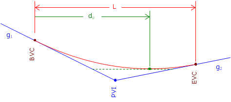
Figure. Distance to High/Low Point
 Equation B-10
The high/low point elevation can be computed by substituting dp in Equation B-7.
In order for Equation B-8 to return a value that makes sense, the grades must have opposite mathematical signs. Consider a +3.00% grade connected to a +1.00% grade with a 500.00 ft long curve. Using Equation B-10 the distance from the BVC to the high/low point is:

The distance exceeds the curve length. What's up with that? Let's sketch it, Figure.
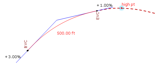
Figure. High Point After the EVC
Remember, we are using only part of the parabolic curve. 7.5000 stations is the distance to the curve's highest point, it's just on that part of the curve we're not using. Our curve's actual highest point is at the EVC.
Similarly for a +0.50% grade connected to a +2.00% with a 400.00 ft curve:

This means the high/low point occurs before the BVC, Figure.
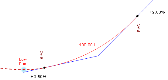
Figure. Low Point Before the BVC
The lowest point for this curve is at the BVC.
Unit - 2
Simple, Compound, Reverse Curves and Vertical Curves
Q1) What is simple curve?
A1)
Simple Curves
Curves are everyday bends furnished with inside the strains of verbal exchange like roads, railways etc. and additionally in canals to result in the sluggish alternate of course.
They also are used with inside the vertical aircraft in any respect adjustments of grade to keep away from the abrupt alternate of grade on the apex.
Curves furnished with inside the horizontal aircraft to have the sluggish alternate in course are referred to as Horizontal curves, while the ones furnished with inside the vertical aircraft to gain the sluggish alternate in grade are referred to as vertical curves.
Curves are laid out at the floor alongside the center line of the work. They can be round or parabolic.
A simple curve consists of a single arc of a circle connecting two straights. It has radius of the same magnitude throughout. In fig. T1 D T2 is the simple curve with T1O as its radius.
Q2) What are the elements if simple curve?
A2)
Elements of simple curve:
Figure shows the elements of a simple curve. They are described as follows, and their abbreviations are given in parentheses.
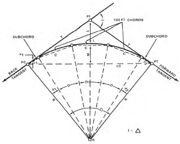
Figure. Elements of a simple curve
Point of Intersection (PI)
The factor of intersection marks the factor in which the lower back and ahead tangents intersect. The surveyor shows it as one of the stations at the initial traverse.
Intersecting Angle (I)
The intersecting attitude is the deflection attitude on the PI.
Radius (R)
The radius is the radius of the circle of which the curve is an arc.
Point of Curvature (PC)
The factor of curvature is the factor in which the round curve begins. The lower back tangent is tangent to the curve at this factor.
Point of Tangency (PT)
The factor of tangency is the stop of the curve. The ahead tangent is tangent to the curve at this factor.
Length of Curve (L)
The period of curve is the gap from the PC to the PT measured alongside the curve.
Tangent Distance (T)
The tangent distance is the gap alongside the tangents from the PI to the PC or PT. These distances are identical on an easy curve.
Central Angle (Δ)
The valuable attitude is the attitude fashioned through radii drawn from the middle of the circle (0) to the PC and PT. The valuable attitude is identical in fee to the I attitude.
Long Chord (LC)
The lengthy chord is the chord from the PC to the PT.
External Distance (E)
The outside distance is the gap from the PI to the midpoint of the curve. The outside distance bisects the indoors attitude on the PI.
Middle Ordinate (M)
The center ordinate is the gap from the midpoint of the curve to the midpoint of the lengthy chord. The extension of the center ordinate bisects the valuable attitude.
Degree of Curve (D)
The diploma of curve defines the “sharpness” or “flatness” of the curve (determine 3). There are definitions usually in use for diploma of curve, the arc definition and the chord definition.
Arc definition.
The arc definition states that the diploma of curve (D) is the attitude fashioned through radii drawn from the middle of the circle (factor O, determine 3) to the ends of an arc one hundred ft. Or 30.forty eight meters lengthy. In this definition, the diploma of curve and radius are inversely proportional the use of the subsequent formula:

Circumference = 2 π Radius
π = 3.141592654
Chords
On curves with lengthy radii, it's miles impractical to stake the curve via way of means of finding the middle of the circle and swinging the arc with a tape.
The surveyor lays those curves out via way of means of staking the ends of a chain of chords (parent 4). Since the ends of the chords lie at the circumference of the curve, the surveyor defines the arc with inside the field.
The duration of the chords varies with the diploma of curve. To lessen the discrepancy among the arc distance and chord distance, the surveyor makes use of the subsequent chord lengths:
The chord lengths above are the most distances wherein the discrepancy among the arc duration and chord duration will fall with inside the allowable blunders for taping, that's 0. 02 foot in keeping with one hundred ft. On maximum creation surveys.
Degree of Curve | Radius Feet | Radius Meters | Chord Feet | Lengths Meters |
From 1 - 3 | 5,730 – 1,910 | 1,745 - 585 | 100 | 30.0 |
3 - 8 | 1,910 - 720 | 585 - 220 | 50 | 15.0 |
8 - 16 | 720 - 360 | 220 - 110 | 25 | 7.5 |
Over 16 | 360 - 150 | 110 - 45 | 10 | 3 |
Deflection Angles
The deflection angles are the angles among a tangent and the ends of the chords from the PC. The surveyor makes use of them to discover the path wherein the chords are to be laid out. The overall of the deflection angles is continually same to 1 1/2 of the I angle. This overall serves as a test at the computed deflection angles.
Q3) What are the methods of curve ranging?
A3)
Methods of curve ranging
The strategies of starting off curves can be divided in classes in line with the tool hired.
1. Linear or chain and tape method: - Linear strategies are the ones in which the curve is about out with chain and tape only.
2. Angular or instrumental method: - instrumental strategies are the ones in which theodolite without or with a series is hired to set out curve.
1. Linear or chain and tape method
The following are the methods of setting out simple circular curves by linear methods and by the use of chain and tape:
1. By ordinates from the Long chord
2. By Successive Bisection of Arcs.
3. By Offsets from the Tangents.
4. By Offsets from Chords Produced.
1. By Ordinates from the Long Chord:
Let T1T2=L= the length of the Long chord
ED= O0= the offset at mid-point (e) of the long chord (the versed sine)
PQ=Ox= the offset at distance x from E
Draw QQ1 parallel to T1 T2 meeting DE at Q1
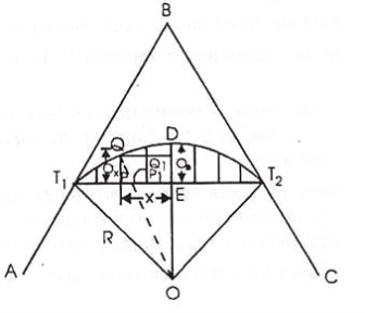
Join OQ cutting T1T2 in P1
From the OQQ1 , OQ2 = QQ12 + OQ12
But OQ = R ; OQ1 = x
And OQ1 = OE + EQ1 = (R – Q3) + Ox
R2 = x2 {(R – O0) + O0}2
Or (R – O0) + Ox = (R2 – x2)
Hence Ox = (R2 – x2)-(R - O)
(Exact) … …(Eqn. 11.10)
Where O0 = ED = OD – OE
= R -  … …(Eqn. 11. 10, a)
When the radius of the curve is large as compared with the length of the long chord, the offset may be equated by the approximate formula which is derived as follows:
Here Ox is assumed to be equal to the radial ordinate QP1.
QP 2R = T1P PT2
Or QP1 = (T1P PT2)/2R
Now T1P = x, and PT2 = L – x
Qx = x(L – x)/2R (approximate) …… ……..(Eqn. 11.11)
2. By Successive Bisections of Arcs:
It is also known as Versing Method. Join T1 T2 and bisect it at E. Set out the offset ED the versed since equal to:
R(1 – cos /2, thus fixing the point Don the curve
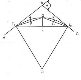
Join T1D and DT2 and bisect them at F and G respectively. Then set outsets FH and GK at F and G each equal to R(1 – cos /4) thus fixing two more points H and K on the curve. Then each of the offsets to be set out at mid points of the chords T1H, HD, DK and KT2 is equal to R(1 – cos /8).By repeating this process, set out as many point as are required.
This method is suitable where the ground outside the curve is not favourable to the tangents.
3. By Offsets from the Tangents:
The offsets may be either radial or perpendicular to the tangents.
(a) By Radial Offsets:
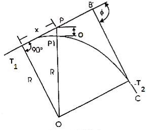
Let Ox = PP1 = the radial offset at P at a distance of x from T1 along the tangent AB
PP1 = OP – OP1 , where OP =  and OP1 = R
Ox =  - R (exact) ………(Eqn . 11. 12)
When the radius is large, the offsets may be calculated by the approximate formula, which may be derived as under:
PT12 = PP1 (2R + PP1)
i.e. x2 = Ox (2R + Ox ) = 2ROx + Ox2
Since Ox2 is very small as compared with 2R, it may be neglected.
x2 = 2R.Ox
Or Ox = x2/2R (approximate) ……(Eqn. 11.13)
(b) By Offsets perpendicular to the Tangents:
Let Ox = PP1 = the perpendicular offset at P at a distance of x from T1 along the tangent AB.
Draw P1P2 parallel to BT1, meeting OT1 at P2
Then P1P2 = PT1 = x; T1P2 = PP1 = Ox.
Now T1P2 = OT1 – OP2
Where OT1 = R, and OP2 = 
Ox = R -  (exact) …..(Eqn. 11.14)
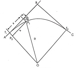
The approximate formula may be obtained similarly as in (a) above,
Ox = x2/2R (approximate) ………(Eqn. 11.5)
Q4) Explain procedure of setting out the curve.
A4)
(i) Locate the tangent points T1 and T2.
(ii) Measure equal distances, say 15 or 30 m along the tangent from T1.
(iii) Set out the offsets calculated by any of the above methods at each distance, thus obtaining the required points on the curve.
(iv) Continue the process until the apex of the curve is reached.
(v) Set out the other half of the curve from the second tangent.
This method is suitable for setting out sharp curves where the ground outside the curve is favorable for chaining.
By Offsets from Chords Produced:
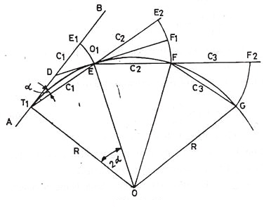
Let AB = the first tangent; T1 = the first tangent point E, F, G etc on the successive points on the curve T1E = T1E1 = C1 = the first chords.
EF, FG, etc. = the successive chords of length C2, C3 etc., each being equal to the full chord.
∠ BT1E = α in radians = the angle between the tangents BT1 and the first chord T1E.
E1E = O1 = the offset from the tangent BT1
E2F = O2 = the offset from the chord T1E produced.
Produce T1E to E2 such tharEE2 = C2. Draw the tangent DEF1 at E meeting the first tangent at D and E2F at F1.
∠BT1E= α in the radians= the angle between the tangents BT1and the first chord T1E.
E1E=O1= the offset from the tangent BT1
E2F=O2= the offset from the chord T1E produced.
Produce T1E to E2 such that EE2= C2.Draw the tangent DEF1at E meeting the first tangent at D and E2Fat F1.
The formula for the offsets may be derived a under:
∠ BT1E=x
∠T1OE=2x
The angle subtended by any chord at the center is twice the angle between the chord and the tangent

But arc T1E is approximately equal to chord T1E = C
C1/R = 2α
Or α = C1/2R
Also 
But arc EE is approximately equal to chord E1E = =O1
O1 = C1 α
Putting here the value of α as calculated above.
O1 = C1 C1/2R = C12/2R ………….(Eqn. 11.16)
O2 = offset E2F = E2F1 + F1F
To find out F2F1, consider the two triangles TEE1 and EF1E2
∠E2EF1 = ∠DET1 (vertically opposite angles):
∠DET1 = ∠DT1E, since DT1 = DE, both being tangents to the circle.
∠E1EF1 = ∠DET1 = ∠DT1E
Both the s being nearly isosceles, may be taken as approximately similar,

∠α
i.e., 
Or E2F1 = (C2 O1)/C2
= C2/C1 C12/2R = (C1C2)/2R
F1F being the offset from the tangent at E, is equal to
EF2/2R = C22/2R
The second offset, O2 = (C1C2)/2R + C22/2R,
 …….(Eqn. 11.17)
Similarly the third offset, O3 = 
Since C2 = C3 = C1 ……….etc,
O3 = C22/R ……………(Eqn. 11. 18)
Each of the remaining offsets O4,O5 etc expect the last one (On) is equal to O3. Since the length of the last chord is usually less than the length of the chord, the last offset,

Q5) Explain procedure of Setting out the Curve
A5)
(i) Locate the tangent points (T1 and T2) and find out their changes. From these changes, calculate lengths of first and last sub-chords and find out the offsets by using the equations 11.16 to 11.19.
(ii) Mark a point E1 along the first tangent T1B such that T1E1 equals the length of the first sub-chord.
(iii) With the zero end of the chain (or tape) at T1 and radius = T1E1, swing an arc E1E and cut off E1E = O1, thus fixing the first point E on the curve.
(iv) Pull the chain forward in the direction of T1E produced until the length EE2 becomes equal to the second chord C2.
(v) Hold the zero end of the chain at E. And radius = C2, swing an arc E2F and cut off E2F = O2, thus fixing the second point F on the curve.
(vi) Continue the process until the end of the curve is reached. The last point fixed in this way should coincide with the previously located point T2. If not, find the closing error. If it is large i.e., more than 2 m, the whole curve are moved sideways by an amount proportional to the square of their distances from the tangent point T1. The closing error is thus distributed among all the points.
This method is very commonly used for setting out road curves.
Q6) How deflection angles are calculated?
A6)
The deflection angles are calculated as follows:
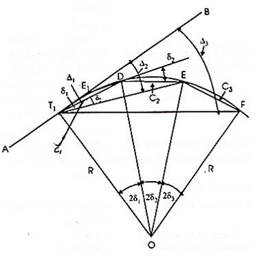
Let T1 and T2 be the tangent points and AB the first tangent to the curve.
D, E, F, etc. =the successive points on the curve,
R = the radius of the curve.
C1, C2, C3 etc. = the lengths of the chords T1D, DE, EF etc., i.e., 1st, 2nd, 3rd chords etc.
δ 1, δ 2, δ 3 etc. = the tangential angles which each of the chords T1 D1, DE, EF, etc., makes with the respective tangents T1, D, E. Etc.
∆1, ∆2, ∆ 3 etc. = the total tangential or deflection angles which the chords T1D, DE, EF, etc. make with the first tangent AB.
Now the chord T1D is approximately equal to arc T1D = C1
∠BT1D = δ1 = ½ ∠T1OD = 2δ1 ∠T1OD = 2δ1

Or C1/R = 2δ1 radians
Or δ1 = C1/R radians
= C1/2R 180/π degrees
= C1/2R 180/π 60 minutes ……..(Eqn. 11.20)
Similarly, δ2 = 1718.9 C2/R ; δ3 = 1718.9 C3/R ; and so on
δn = 1718.9 Cn/R minutes ……..(Eqn. 11.21)
Since each of the chord lengths C2, C3, C4…………. Cn-1 is equal to the length of the full chord, δ2 = δ3 = δ4………….. δ n-1.
The total tangential angle (1) for the first chord (T1D)
= ∠BT1D = δ1
1 = δ1
The total tangential angle (2) for the second chord (DE) = ∠BT1E
But ∠BT1E = ∠BT1D + ∠DT1E
It is well known preposition of geometry that the angle between the tangent and a chord equals the angle which the chord subtends in the opposite segment.
Now ∠DT1E is the angle subtended by the chord DE in the opposite segment, therefore, it is equal to the tangential angle (δ2) between the tangent D and the chard DE
2 = δ1 + δ2 = 1 + δ2
SImilarly, 3 = δ1 + δ2 + δ3 = 2 + d3
n + δ1 + δ2 + δ3 ………..+ δn
= n-1 + δn ………..(Eqn. 11.22)
Check:
The total deflection angle BT1 T2 = n = /2
Where φ is the deflection angle of the curve.
If the degree of die curve (D) is known, the deflection angle for 30 m chord is equal 1/2D degrees, and that for the sub-chord of length C1,
= C1/30 D/2 degrees
δ1 = (C1 D)/60 ; δ2 = δ3 ……δn-1 = D/2;
δn = (Cn D)/60 …………… (Eqn. 11.23)
Q7) Explain procedure of Setting out the Curve
A7)
(i) Locate the tangent factors (T1 and T2) and discover their changes. From those changes, calculate the lengths of first and final sub-chords and the entire deflection angles for all factors at the curve as defined above.
(ii) Set up and stage the theodolite at the primary tangent factor (T1).
(iii) Set the veneer A of the horizontal circle to 0 and direct the telescope to the ranging rod on the intersection factor B and bisect it.
(iv) Loosen the vernier plate and set the veneer A to the primary deflection perspective Δ1, the telescope is accordingly directed alongside T1D. Then alongside this line, degree T1D same in period to the primary sub-chord, accordingly solving the primary factor D at the curve.
(v) Loosen the top clamp and set the vernier A to the second one deflection perspective Δ2, the road of sight is now directed alongside T1E. Hold the 0 quit of the chain at D and swing the alternative quit till the arrow held at that quit is bisected via way of means of the road of sight, accordingly solving the second one factor (E) at the curve.
(vi) Continue the technique till the quit of the curve is reached. The quit factor accordingly positioned ought to coincide with the formerly positioned factor (T2). If not, the space among them is the ultimate error. If it's far inside the permissible limit, simplest the previous couple of pegs can be adjusted; in any other case the curve have to be set out again.
Q8) What is two theodolite method?
A8)
Two-Theodolite Method:
This method is very useful in the absence of chain or tape and also when ground is not favourable for accurate chaining. This is simple and accurate method but requires essentially two instruments and two surveyors to operate upon them, so it is not as commonly used as the method of deflection angles. In this method, the property of circle ‘that the angle between the tangent and the chord equals the angle which that chord subtends in the opposite segment’ is used.
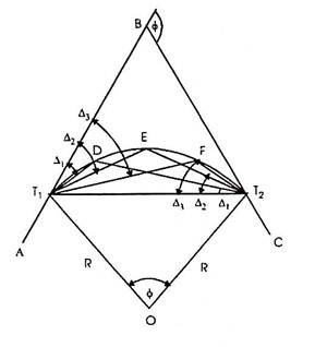
Let D, E, F, etc. be the points on the curve. The angle (Δ1) between the tangent T1B and the chord T1D i.e. ∠BT1 D = ∠T1T2D. Similarly, ∠BT1E = ∆2 = ∠T1T2 E, and ∠BT1F = ∆3 = ∠T1T2F etc. The total deflection angles ∆1, ∆2, ∆3, etc. are calculated from the given data as in the first method (i.e. as in Rankine’s method of deflection angles).
Procedure of setting out the curve:
(i) Set up two theodolites, one at T1 and the other at T2.
(ii) Set vernier of the horizontal circle of each of the theodolites to zero.
(iii) Turn the instrument at T1 to sight the intersection point B and that at T2 to sight T1.
(iv) Set the vernier of each of the instruments to read the first deflection angle Δ1. Now the line of sight of the instrument at T1 is along T1D and that of the instrument at T2 is along T2D. Their point of intersection is the required point on the curve Direct the assistant to move the ranging rod until it is sighted exactly by both the theodolites, thus fixing the point D on the curve.
(v) Then set the vernier of each of the instrument to the second deflection angle Δ2, proceed as before to obtain the second point (E) on the curve.
(vi) Repeat the process until the whole curve is set out.
Obstacles in setting out curves
After reading this article you will learn about the difficulties faced during ranging simple curves.
Case I:
When the point of intersection of the tangents is inaccessible
It so generally takes place that the intersection factor (B) turns into in accessessible because of impediment like lake, river or timber etc. Let AB and BC be the 2 tangents intersection on the factor B, and T1and T2 the tangent factors.
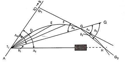
Since the intersections factor (B) is used for measuring the deflection angle (ɸ) and additionally for finding the tangent factors T1 and T2, the field- paintings be organized to degree ɸ and to discover T1and T2without going at B
Producers:
(i) Select two indivisible points M and N suitably on the tangents AB and BC respectively and measure MN accurately.
(ii) Measure the angles AMN (α) and CNM (β) by setting the theodolite at M and N respectively.
Now in BMN,
∠BMN = 180o – α
∠BNM = 180o – β
The deflection angle () = ∠BMN + ∠BNM
= (180o – α) + (180o – β)
= 360o – (α + β)
(iii) Solve the ∆ BMN by the sine rule for the distance BM and BN.

(iv) Calculate the tangent lengths BT1 = BT2 = R tan φ/2
(v) Now the distance MT1 = BT1-BM and NT2 = BT2-BN
(vi) Measure the distance MT1 from M along BA, thus locating the first tangent point T1. Similarly locate T2 by measuring NT2 from N along BC.
When a clear line MN is not available, a traverse is run between M and N to find the length and bearing of the line MN. Then from the known bearings of the tangents and the calculated bearing of the line MN, calculate the angles α and β and proceed as above.
Q9) Explain case 2 in two theodolite method.
A9)
When the complete curve cannot be set out from the starting point due to the obstructed vision:
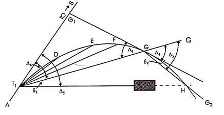
When the curve is brief and the floor is loose from obstructions like buildings, timber etc., the entire curve may be set out from the primary tangent factor (T1). However it isn't always usually feasible to have quick curves and floor loose from obstacles.
In such instances the device must be installation at one or extra factors alongside the curve. The following manner can be followed in such instances.
Procedure: Let D, E, F, G, H etc. be the factors at the curve, and G is the remaining factor placed from the device at T1 while it's far determined vital to shift the device. Let deflection perspective for G be ∆4, then deflection perspective for the subsequent factor H must be Δ5.
(i) Shift the device and set it up at G.
(ii) Set the vernier A to zero, take an again sight on T1 and transit the telescope. The line of sight is accordingly directed alongside GG’ i.e. alongside T1 G produced.
(iii) Loose the higher clamp and set the vernier to study the deflection perspective ∆5, accordingly directing the road of sight alongside GH. [By Geometry, ∠G’GH = ∠BT1H. (Please see proof at the end)].
(iv) Locate H via way of means of measuring a distance same to chord period alongside GH.
(v) Then the usage of the equal tabulated deflection angles, keep the starting up of the curve from G as usual.
Q10) What is compound curve?
A10)
Compound Curves
A compound curve is or extra easy curves that have exclusive centers, bend with inside the equal direction, lie at the equal facet in their not unusual place tangent, and hook up with shape a non-stop arc.
The factor in which the 2 curves connect (namely, the factor at which the PT of the primary curve equals the PC of the second one curve) is called the factor of compound curvature (PCC).
Since their tangent lengths vary, compound curves healthy the topography an awful lot higher than easy curves.
These curves effortlessly adapt to mountainous terrain or regions reduce with the aid of using large, winding rivers.
However, because compound curves are extra unsafe than easy curves, they need to in no way be used in which an easy curve will do.
Elements of compound Curves
A compound curve consists of two (or more) circular curves between two main tangents joined at point of compound curve (PCC). Curve at PC is designated as 1 (R1, L1, T1, etc) and curve at PT is designated as 2 (R2, L2, T2, etc).
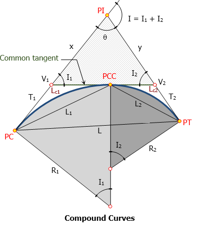
Elements of compound curve
- PC = point of curvature
- PT = point of tangency
- PI = point of intersection
- PCC = point of compound curve
- T1 = length of tangent of the first curve
- T2 = length of tangent of the second curve
- V1 = vertex of the first curve
- V2 = vertex of the second curve
- I1 = central angle of the first curve
- I2 = central angle of the second curve
- I = angle of intersection = I1 + I2
- Lc1 = length of first curve
- Lc2 = length of second curve
- L1 = length of first chord
- L2 = length of second chord
- L = length of long chord from PC to PT
- T1 + T2 = length of common tangent measured from V1 to V2
- θ = 180° - I
- x and y can be found from triangle V1-V2-PI.
- L can be found from triangle PC-PCC-PT
Q11) Explain setting out curves for compound curve in detail.
A11)
Setting out the curve
Step 1: Locate the tangent factor T, through measuring returned the whole tangent period (Tt) alongside the returned tangent, from the factor of intersection V. Likewise, find the tangent factor T' through measuring alongside the ahead tangent the gap Tt from V. Setting out of the transition curve:
Step 2: Set a theodolite over the factor T. Set the vernier A to 0, and clamp the top plate.
Step 3: Direct the road of sight of theodolite to the intersection factor V, and clamp the decrease plate.
Step 4: Release the top plate. Set the vernier A to the primary deflection perspective (a1). The line of sight now factors closer to the primary peg at the transition curve.
Step 5: With the 0 of the tape pinned at T and an arrow saved on the mark similar to the primary period of the chord, the assistant will swing the tape until the arrow is bisected through the road of sight. Fix the primary peg on the arrow factor.
Step 6: Set the vernier A on the second one deflection perspective (a2) to direct the road of sight to the second one peg.
Step 7: With the 0 of the tape pinned at T, and retaining an arrow on the mark similar to the whole period of the primary and 2d chords, the assistant will swing an arc until the arrow is bisected through the road of sight. Fix the second one peg on the arrow factor. It must be remembered that the gap is measured from the factor T and now no longer from the preceding factor.
Step 8: repeat steps (6) and (7) until the closing factor C at the transition curve is reached. Setting out of the round curve:
Step 9 : For starting up the round curve CC', shift the theodolite to junction factor C. Orient the theodolite as regards to the not unusual place tangent CC1 through directing the road of sight closer to CT with the vernier.
Step 10: Plunge the telescope. The line of sight is now directed alongside the tangent C1C produced. The deflection angles D1, D2, etc. were calculated as regards to the tangent C1C produced at C
The line of sight is now successfully oriented, and the studying of the vernier A is 0.
Step 11 : Set the vernier A to the primary deflection perspective D1, and find the primary peg at the round curve at a distance of c' from C, in which c' is period of the primary sub-chord.
Step 12: Likewise, find the second one peg at the round curve at the gap c identical to the ordinary chord from the primary peg with the deflection perspective D2 at C.
Step 13: Continue the above procedure until the junction factor C' is reached. Step 14: Set out the transition curve T'C' from T' the use of the identical method as that for the transition curve TC.
Q12) Explain reverse curve in detail.
A12)
Reverse Curves
An opposite curve consists of or greater easy curves handing over contrary directions. Their factors of intersection lie on contrary ends of a not unusual place tangent, and the PT of the primary curve is coincident with the PC of the second.
This factor is known as the factor of opposite curvature (PRC). Reverse curves are beneficial whilst laying out such things as pipelines, flumes, and levees. The surveyor may additionally use them on low-pace roads and railroads.
They can't be used on high-pace roads or railroads due to the fact that they can't be nicely super elevated on the PRC. They are every so often used on canals, however most effective with severe caution, due to the fact that they make the canal hard to navigate and make contributions to erosion.
The inexperienced device is an unmarried tangent round arc. Even eleven though it's far an especially sharp curve, it takes up the maximum space (to take in much less space, it might want to be even sharper).
Its number one shortcomings are the tangent-curve-tangent transitions and centrifugal pressure situation requiring a decrease velocity and better super elevation.
The crimson device is a five-middle compound curve the usage of consecutive curves of various radii. The idea at the back of this utility became mentioned in Chapter D.
While higher than the unmarried curve and taking on much less space, it may nevertheless be tricky on the curve-curve transitions for the reason that forces can extrude considerably until speeds are reduced.
The blue device is a spiraled horizontal curve: a front spiral right into a round arc into a go out spiral. In this example, that is a symmetric device with front and go out spirals reflect pictures of every other, despite the fact that that need not be the case.
Not handiest does this curve device offer the smoothest velocity and path changes, it's far the maximum cushy and takes up the least space.
Elements of reverse Curves
Reversed curve, though pleasing to the eye, would bring discomfort to motorist running at design speed. The instant change in direction at the PRC brought some safety problems. Despite this fact, reversed curves are being used with great success on park roads, formal paths, waterway channels, and the like.
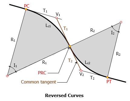
Elements of Reversed Curve
- PC = point of curvature
- PT = point of tangency
- PRC = point of reversed curvature
- T1 = length of tangent of the first curve
- T2 = length of tangent of the second curve
- V1 = vertex of the first curve
- V2 = vertex of the second curve
- I1 = central angle of the first curve
- I2 = central angle of the second curve
- Lc1 = length of first curve
- Lc2 = length of second curve
- L1 = length of first chord
- L2 = length of second chord
- T1 + T2 = length of common tangent measured from V1 to V2
Q13) Explain setting out the curve for reverse curve in detail.
A13)
Setting out the curve
An opposite curve includes round arcs of same or distinct radii returning contrary guidelines with a general tangent on the junction of the arcs.
The junction factor is said to own opposite curvature,
The opposite curve is moreover known as a serpentine curve. Reverse curves are normally wont to attach parallel roads or railway strains, or whilst strains intersect at a genuinely small angle.
These curves are well matched for railway sidings, metropolis roads, etc. But they should be averted as a ways as viable for essential tracks or highways for the following reasons:
1. Super elevation cannot be supplied on the reason of opposite curvature.
2. A snappy converting of course could be risky for a car.
3. A snappy converting of cant reasons soreness to passengers.
Reverse curves are normally short.
And for this reason they may be began out through the chain and tape method.
Step 1: Locate the tangent factor T, through measuring returned the whole tangent period (Tt) alongside the returned tangent, from the factor of intersection V. Likewise, find the tangent factor T' through measuring alongside the ahead tangent the gap Tt from V. Setting out of the transition curve :
Step 2: Set a theodolite over the factor T. Set the vernier A to 0, and clamp the top plate.
Step 3: Direct the road of sight of theodolite to the intersection factor V, and clamp the decrease plate.
Step 4: Release the top plate. Set the vernier A to the primary deflection perspective (a1). The line of sight now factors closer to the primary peg at the transition curve.
Step 5: With the 0 of the tape pinned at T and an arrow saved on the mark similar to the primary period of the chord, the assistant will swing the tape until the arrow is bisected through the road of sight. Fix the primary peg on the arrow factor.
Step 6: Set the vernier A on the second one deflection perspective (a2) to direct the road of sight to the second one peg.
Step 7: With the 0 of the tape pinned at T, and retaining an arrow on the mark similar to the whole period of the primary and 2d chords, the assistant will swing an arc until the arrow is bisected through the road of sight. Fix the second one peg on the arrow factor. It must be remembered that the gap is measured from the factor T and now no longer from the preceding factor.
Step 8: repeat steps (6) and (7) until the closing factor C at the transition curve is reached. Setting out of the round curve:
Step 9 : For starting up the round curve CC', shift the theodolite to junction factor C. Orient the theodolite as regards to the not unusual place tangent CC1 through directing the road of sight closer to CT with the vernier.
Step 10: Plunge the telescope. The line of sight is now directed alongside the tangent C1C produced. The deflection angles D1, D2, etc. were calculated as regards to the tangent C1C produced at C
The line of sight is now successfully oriented, and the studying of the vernier A is 0.
Step 11 : Set the vernier A to the primary deflection perspective D1, and find the primary peg at the round curve at a distance of c' from C, in which c' is period of the primary sub-chord.
Step 12: Likewise, find the second one peg at the round curve at the gap c identical to the ordinary chord from the primary peg with the deflection perspective D2 at C.
Step 13: Continue the above procedure until the junction factor C' is reached. Step 14: Set out the transition curve T'C' from T' the use of the identical method as that for the transition curve TC.
Q14) What is vertical curve?
A14)
Vertical Curves
Vertical Curves are the second one of the 2 essential transition factors in geometric layout for highways, the primary being Horizontal Curves. A vertical curve gives a transition among sloped roadways, permitting an automobile to barter the elevation fee alternate at a slow fee as opposed to a pointy cut.
The layout of the curve is depending on the meant layout velocity for the roadway, in addition to different elements inclusive of drainage, slope, appropriate fee of alternate, and friction.
These curves are parabolic and are assigned stationing primarily based totally on a horizontal axis.
Elements of vertical curves
Vertical curves provide a transition between two sloped roadways, allowing vehicles to negotiate the elevation rate change gradually rather than at sharp cut.
The design of the curve is dependent on:
- The intended design speed for the roadway
- Drainage
- Slope
- Acceptable rate of change
- Friction
These curves are parabolic and are assigned stationing based on a horizontal axis.
Two types of vertical curves:
- Sag Curves
Used where the change in grade is positive, such as valleys defined points:
- PVC (Point of Vertical Curve) – start point of the curve
- PVI (Point of Vertical Intersection)
- PVT (Point of Vertical Tangency) – end point of the curve
2. Crest Curves
Used when the change in grade is negative, such as hills3 defined points:
- PVC
- PVI
- PVT
The roadway grade that approaches a Point of Vertical Curve (PVC) is g1, measured in ft/ft (or m/m)
The roadway grade that leaves a PVT is g2, measured in ft/ft (or m/m)
Types
- Summit curve: When two grades meet at the summit and the curve will have convexity upwards, the curve is simply referred as summit curve.
- Valley (Sag) curve: When two grades meet at the valley (sag) and the curve will have convexity downwards, the curve is simply referred as the valley (sag) curve.
Tangent correction
The format of the curve is relying at the supposed format pace for the roadway, similarly to distinct factors such as drainage, slope, suitable charge of alternate, and friction Vertical curves offer a transition among sloped roadways, permitting cars to barter the elevation fee extrude step by step as opposed to a sharp cut.
The format of the curve is relying at the supposed format pace for the roadway, similarly to distinct factors such as drainage, slope, suitable charge of alternate, and friction
Q15) Explain location of highest or lowest point in detail.
A15)
Location of highest or lowest point
High or Low Point
When asked where a curve's highest, or lowest, point is, most people assume it is at the middle of the curve. This is true only under a specific condition. The high or low point occurs where the curve changes direction vertically. This happens where the curve tangent has a 0% grade, Figure.
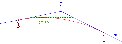
a. Crest Curve

b. Sag Curve
Figure. High and Low Point Conditions
On a crest curve, the tangent grade begins at g1 and deceases uniformly (by k). As long as the grade is positive, the curve elevation keeps increasing. At 0%, the curve reaches its maximum elevation and after that the grade decreases, causing curve elevations to drop.
The opposite is true for a sag curve. As the grade decreases, while it is still negative curve elevations decrease. When the grade is 0%, the elevation decrease stops and as the tangent slope increases so do curve elevations.
The only condition under which the high or low point occurs at the center of the curve is when incoming and outgoing grades are numerically equal but have opposite mathematical signs (eg, +2% into -2%, -3% into +3%).
The distance from the BVC to the high/low point, dp in Figure, is determined from Equation B-10:
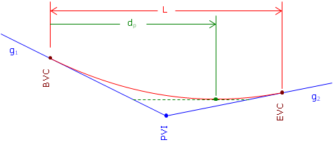
Figure. Distance to High/Low Point
 Equation B-10
The high/low point elevation can be computed by substituting dp in Equation B-7.
In order for Equation B-8 to return a value that makes sense, the grades must have opposite mathematical signs. Consider a +3.00% grade connected to a +1.00% grade with a 500.00 ft long curve. Using Equation B-10 the distance from the BVC to the high/low point is:

The distance exceeds the curve length. What's up with that? Let's sketch it, Figure.
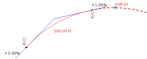
Figure. High Point After the EVC
Remember, we are using only part of the parabolic curve. 7.5000 stations is the distance to the curve's highest point, it's just on that part of the curve we're not using. Our curve's actual highest point is at the EVC.
Similarly for a +0.50% grade connected to a +2.00% with a 400.00 ft curve:

This means the high/low point occurs before the BVC, Figure.
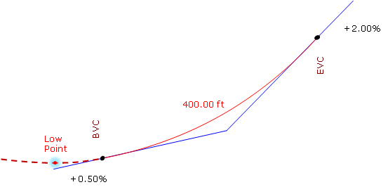
Figure. Low Point Before the BVC
The lowest point for this curve is at the BVC.