Unit - 4
Network layer and transport layer
Q1) Define IPv4 address?
A1) IPv4 is a version 4 of IP. It is a current version and the most commonly used IP address. It is a 32-bit address written in four numbers separated by 'dot', i.e., periods. This address is unique for each device.
For example, 66.94.29.13
The above example represents the IP address in which each group of numbers separated by periods is called an Octet. Each number in an octet is in the range from 0-255. This address can produce 4,294,967,296 possible unique addresses.
In today's computer network world, computers do not understand the IP addresses in the standard numeric format as the computers understand the numbers in binary form only. The binary number can be either 1 or 0. The IPv4 consists of four sets, and these sets represent the octet. The bits in each octet represent a number.
Each bit in an octet can be either 1 or 0. If the bit is 1, then the number it represents will count, and if the bit is 0, then the number it represents does not count.
Representation of 8 Bit Octet

Fig 1: Structure of 8-bit octet
The above representation shows the structure of 8- bit octet.
Now, we will see how to obtain the binary representation of the above IP address, i.e., 66.94.29.13
Step 1: First, we find the binary number of 66

To obtain 66, we put 1 under 64 and 2 as the sum of 64 and 2 is equal to 66 (64+2=66), and the remaining bits will be zero, as shown above. Therefore, the binary bit version of 66 is 01000010.
Step 2: Now, we calculate the binary number of 94
To obtain 94, we put 1 under 64, 16, 8, 4, and 2 as the sum of these numbers is equal to 94, and the remaining bits will be zero. Therefore, the binary bit version of 94 is 01011110.
Step 3: The next number is 29
To obtain 29, we put 1 under 16, 8, 4, and 1 as the sum of these numbers is equal to 29, and the remaining bits will be zero. Therefore, the binary bit version of 29 is 00011101.
Step 4: The last number is 13
To obtain 13, we put 1 under 8, 4, and 1 as the sum of these numbers is equal to 13, and the remaining bits will be zero. Therefore, the binary bit version of 13 is 00001101.
Q2) Write the drawback of IPv4?
A2) Drawback of IPv4
Currently, the population of the world is 7.6 billion. Every user is having more than one device connected with the internet, and private companies also rely on the internet. As we know that IPv4 produces 4 billion addresses, which is not enough for each device connected to the internet on a planet.
Although various techniques were invented, such as variable- length mask, network address translation, port address translation, classes, inter-domain translation, to conserve the bandwidth of IP address and slow down the depletion of an IP address. In these techniques, public IP is converted into a private IP due to which the user having public IP can also use the internet. But still, this was not so efficient, so it gave rise to the development of the next generation of IP addresses, i.e., IPv6.
Q3) What is subnetting?
A3) Subnetting
● Subnetting is a technique for dividing a single physical network into smaller sub-networks. A subnet is a collection of subnetworks. The small networks section and the host segment combine to form an internal address. A subnetwork is created by accepting the bits from the IP address host component and using them to create a number of mini subnetworks within the original network.
● Network bits are turned into host bits during the subnetting process. The process of subnetting is used to slow down the depletion of IP addresses. It enables the administrator to divide a single class A, B, or C into smaller portions. VLSM (Variable Length Subnet Mask) and FLSM (Fixed Length Subnet Mask) are used in subnetting (Fixed Length Subnet Mask). A Variable Length Subnet Mask is a method of dividing the IP address space into subnets of varying sizes. Memory waste is reduced with VLSM. A Fixed Length Subnet Mask is a method of dividing the IP address space into subnets of the same size.
Advantages
● The number of authorized hosts in a local area network can be increased via subnetting.
● Subnetting reduces the amount of broadcast traffic and thus the amount of network traffic.
● Subnetworks are simple to set up and manage.
● Subnetting increases the address's versatility.
● Rather than using network security across the entire network, subnetwork security can be easily implemented.
Disadvantages:
● Subnetting is a time-consuming and costly operation.
● A trained administrator is required to carry out the subnetting operation.
Q4) What do you mean by supernetting?
A4) Supernetting is a technique for combining many subnetworks into a single network. Its procedure is the inverse of that of subnetting. Mask bits are relocated to the left of the default mask in supernetting, and network bits are changed to hosts bits. Router summarization and aggregation are other terms for supernetting. It increases the number of host addresses while decreasing the number of network addresses. The supernetting process is carried out by the Internet service provider in order to achieve the most efficient IP address allocation.
It routes network traffic across the internet using the CIDR mechanism, which stands for Classless inter-domain routing. For network traffic routing, CIDR integrates numerous sub networks and connects them. In other words, we can say that CIDR organizes the IP Addresses in the sub networks independent of the value of the Addresses.
Advantages:
● Supernetting minimizes the network's traffic on the internet.
● The speed of looking up a routing table is improved via supernetting.
● The size of the router's memory table was reduced as the number of routing information entries was consolidated into a single entry, conserving memory space.
● The router has a feature that allows it to isolate topology changes from the other routers.
Disadvantages:
● The block combinations should be formed in power 2 alternately; if three blocks are necessary, four blocks must be assigned.
● While it does a good job of combining multiple entries into one, it falls short of covering all of the bases.
● The network as a whole must be in the same class.
Q5) Write the difference between subnetting and supernetting?
A5) Difference between subnetting and supernetting
● Subnetting divides a network into subnetworks, but supernetting joins them together to form a single network.
● Subnetting increases the number of network bits by converting host bits to network bits, whereas supernetting increases the number of host bits by converting network bits to host bits.
● Subnetting slows down address depletion, but supernetting speeds up the routing process.
● VLSM and FL methods are used in subnetting, while CIDR is used in supernetting.
● Mask bits in subnetting are shifted to the right of the default mask, but mask bits in supernetting are transferred to the left of the default mask.
Q6) Describe distance vector?
A6) A distance-vector routing (DVR) protocol is that it requires that a router should inform its neighbors of topology changes takes place periodically. Historically it is known as the old ARPANET routing algorithm (or it is also known as Bellman-Ford algorithm).
Bellman Ford Basics – Each router maintains its Distance Vector table which are containing the distance between itself and all possible destination nodes. Distances is based on a chosen metric and are computed using information from the neighbors’ distance vectors.
Example - Consider 3-routers X5 Y and Z as shown in figure. Each router have their routing table. Every routing table will contain distance to the destination nodes.
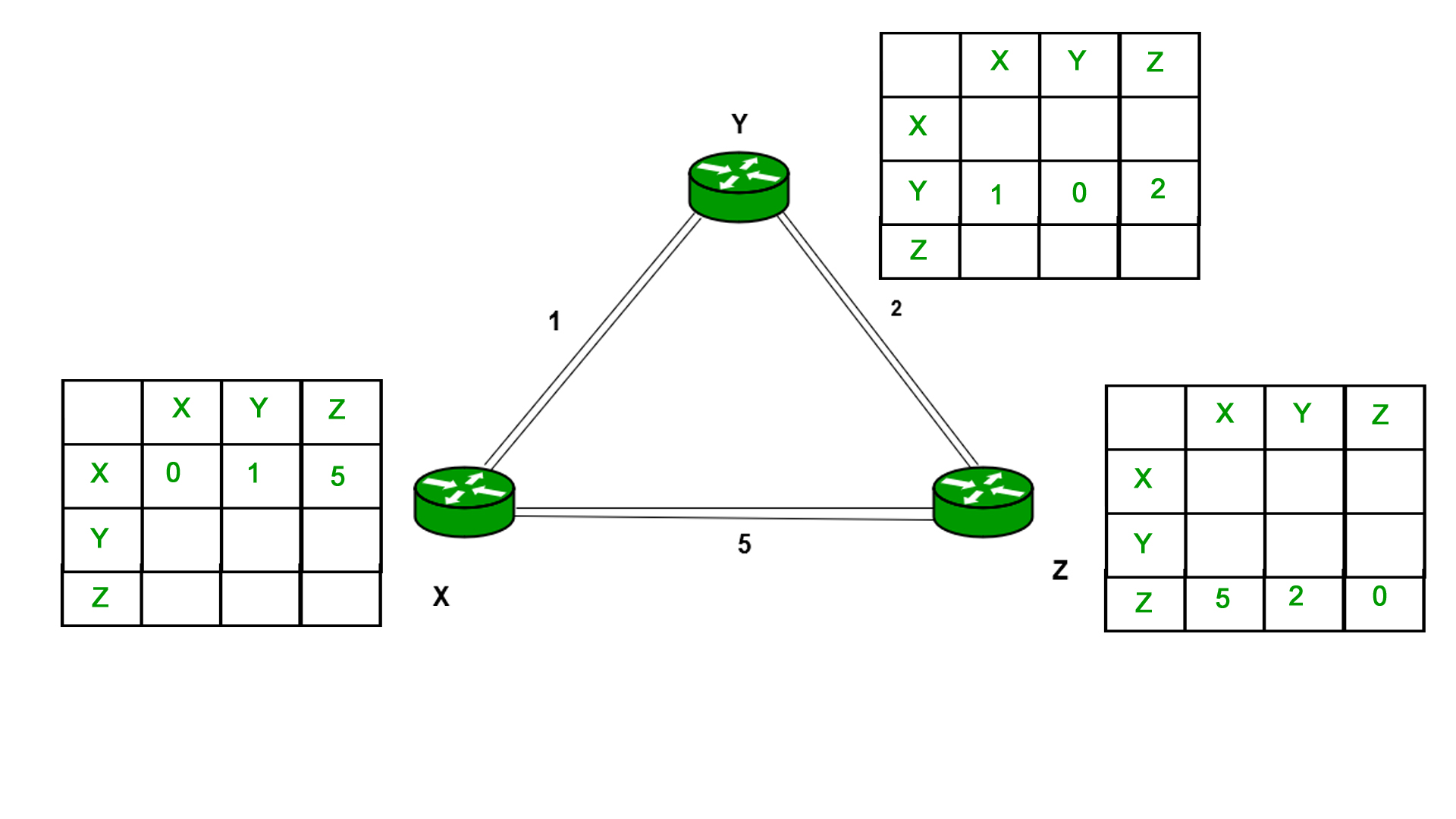
Consider router X 5 X will share it routing table to neighbors and neighbors will share it routing table to it to X and distance from node X to destination will be calculated using bellmen- ford equation.
Dx(y) = min { C(x5v) + Dv(y)} for each node y ∈ N
As we can see that distance will be less going from X to Z when Y is intermediate node (hop) so it will be update in routing table X.

Similarly for Z also –
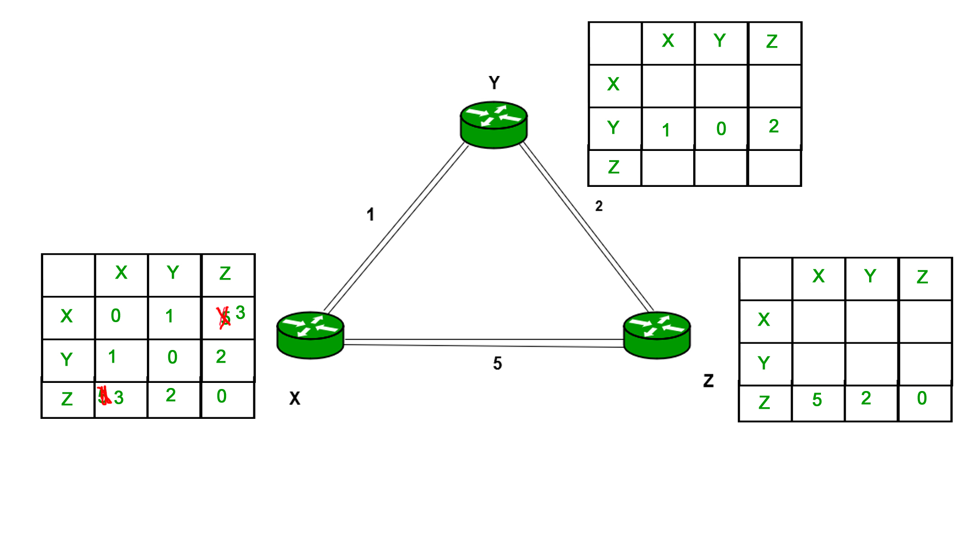
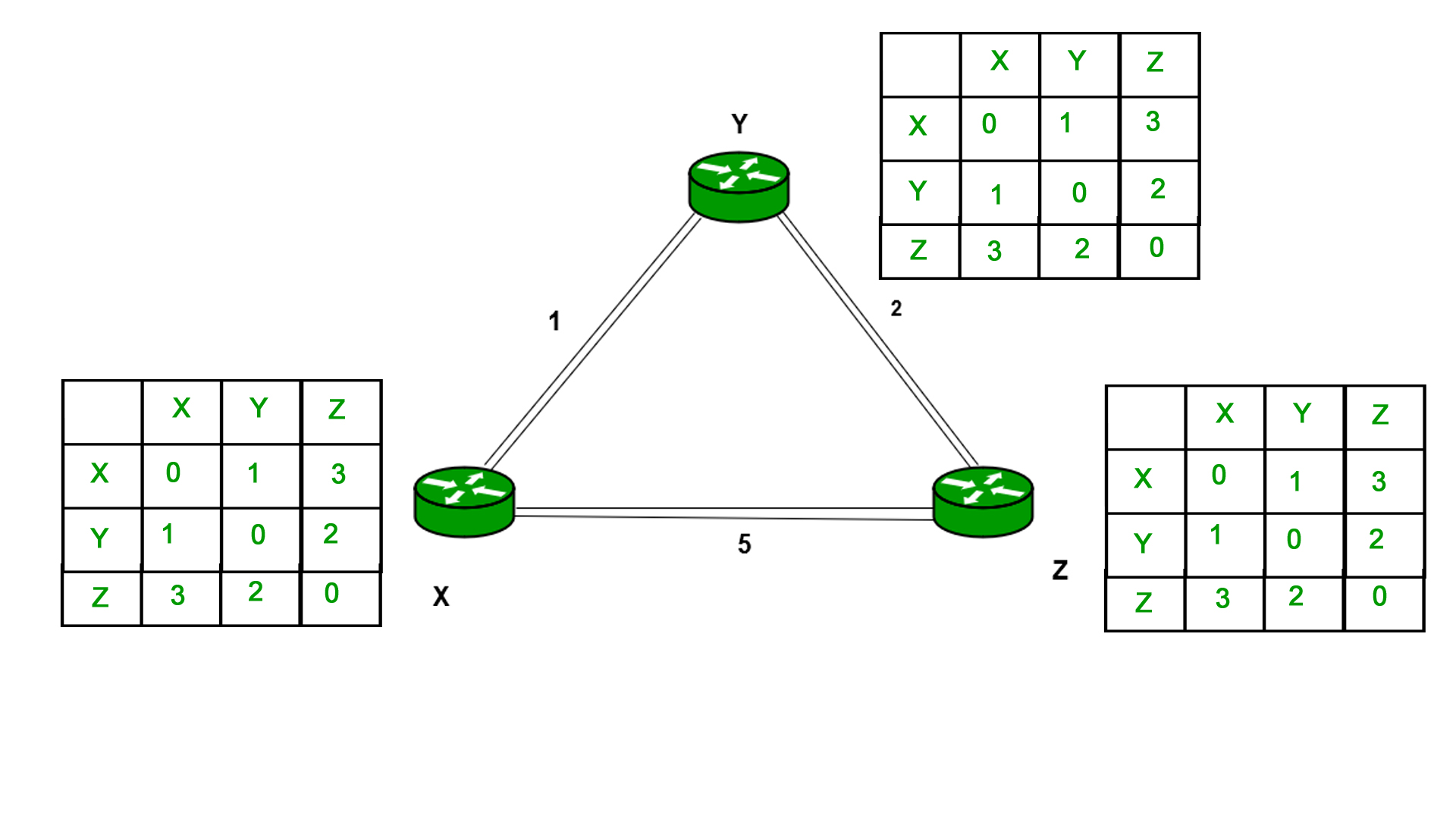
Finally, the routing table for all is shown above image.
Information which are kept by DV router -
● Each router has its own ID
● IT is associated with each link that are connected to a router,
● There is a cost of the link (static or dynamic).
● Intermediate hops
Distance Vector Table Initialization -
● Distance to itself = 0
● Distance to all other routers = infinity number.
Distance Vector Algorithm –
- A router transmits its distance vector to that of each of its neighbors in that of a routing packet.
- Each router receives and then saves the most recently received distance vector from each of its neighbors.
- A router recalculates its distance vector when the following happens:
○ It receives a distance vector from that of its neighbor containing different information than before.
○ It discovers that a link to a neighbor has slow down.
The DV calculation is based on minimizing the cost to each destination
Dx(y) = Estimate of least cost from x to y
C(x,v) = Node x knows cost to each neighbor v
Dx = [Dx(y): y ∈ N] = Node x maintains distance vector
Node x also maintains its neighbors’ distance vectors
– For each neighbor v, x maintains Dv = [Dv(y): y ∈N ]
Note –
● From time-to-time, each of the node sends its own distance vector which is estimate to its neighbors.
● When a node x receives new DV estimate from any neighbor v, it saves v’s distance vector and it updates its own DV using B-F equation:
● Dx(y) = min { C(x,v) + Dv(y)} for each node y ∈ N
Q7) Write the advantages and disadvantages of distance vector?
A7) Advantages of Distance Vector routing are as follows –
● It is very simple to configure and it maintains link state routing.
Disadvantages of Distance Vector routing are as follows –
● It is very slow to converge than link state.
● It is at high risk from the count-to-infinity problem.
● It creates more traffic than that of link state since a hop count changes must be propagated to all routers and then processed on each router. Hop count updates take place on periodic basis, even if there are no networks changes in the topology, so bandwidth-wasting broadcasts still occur.
● For the very large networks, distance vector routing results in larger routing tables than link state since each router must know also about all of the other routers. This can also lead to congestion on WAN links.
Q8) Explain about link state?
A8) Unicast
Unicast is the transmission from single sender to single receiver. It has point to point communication between the sender end and the receivers end. There are various types of unicast protocols for example TCP, HTTP, etc.
● The most commonly used unicast protocol is TCP. It is a connection oriented protocol that will rely on an acknowledgement from that of the receiver side.
● HTTP is HyperText Transfer Protocol. It is an object oriented protocol for communication.
Three major protocols for unicast routing are:
- Distance Vector Routing
- Link State Routing
- Path-Vector Routing
Link State Routing –
The second family of routing protocols is Link state routing. While the distance vector routers uses a distributed algorithm to compute to their routing tables and link-state routing uses its link-state routers for the exchanging of messages that allows each of the router to learn the entire of the network topology. Based on this learned topology, each router is then will able to compute its own routing table by using a shortest path computation.
Link state routing protocols features –
● Link state packet – It is a small packet which contains routing information.
● Link state database – It is a collection of information gathered from the link state packet.
● Shortest path first algorithm (Dijkstra algorithm) – The calculation performed on the database which results into the shortest path
● Routing table – It is a list of known paths and interfaces.
Calculation of shortest path –
To find shortest path, each node need to run the famous Dijkstra algorithm. Following are the steps of this algorithm:
Step-1: The node is taken and then chosen as a root node of the tree, this will creates the tree with a single node, and now set the total cost of each of the node to some value based on the information in the Link State Database
Step-2: Now the node will select one node, among all of the nodes that is not in the tree like structure, which is nearest to that of the root, and then adds this to the tree. Then the shape of the tree gets changed.
Step-3: After this entire node is added to the tree, then the cost of all the nodes which is not in the tree needs to be updated because of the paths may have been changed.
Step-4: The node repeats the Step 2. And Step 3. Until entire nodes are added in the tree
Link State protocols in comparison to Distance Vector protocols have:
- Large amount of memory is required.
- Many CPU circles are required for shortest path computations.
- If the network uses the small bandwidth then it quickly reacts to changes in the topology.
- All items in the database must be sent to the neighbors to form link state packets.
- All neighbors must be trusted in the topology.
- Authentication mechanisms can be used to avoid undesired adjacency and problems.
- In the link state routing no split horizon techniques are possible.
Advantages:
● This protocol has more information of the inter-network than any other distance vector routing system since it keeps distinct tables for the best and backup routes.
● The concept of triggered updates is used, therefore there is no waste of bandwidth.
● When there is a topology change, partial updates will be triggered, thus the entire routing table will not need to be updated.
Q9) Write the difference between distance vector and link state?
A9) Here are some main difference between these Distance Vector and Link State routing protocols:
Distance Vector | Link State |
Distance Vector protocol sends the entire routing table. | Link State protocol sends only link-state information. |
It is susceptible to routing loops. | It is less susceptible to routing loops. |
Updates are sometimes sent using broadcast. | Uses only multicast method for routing updates. |
It is simple to configure. | It is hard to configure this routing protocol. |
Does not know network topology. | Know the entire topology. |
Example RIP, IGRP. | Examples: OSPF IS-IS. |
Q10) Define path vector?
A10) Path Vector Routing is routing algorithm in unicast routing protocol of network layer, and it is useful for interdomain routing.
BGP and other path vector (PV) protocols are utilized between domains, or autonomous systems. In a path vector protocol, a router receives not only the distance vector for a certain destination from its neighbor, but also path information (also known as BGP path characteristics), which the node can use to calculate (via the BGP path selection process) how traffic is routed to the destination AS.
The principle of path vector routing is similar to that of distance vector routing. It assumes that there is one node in each autonomous system that acts on behalf of the entire autonomous system is called Speaker node.
The speaker node in an AS creates a routing cable and advertises to the speaker node in the neighboring ASs
A speaker node advertises the path, not the metrics of the nodes, in its autonomous system or other autonomous systems
It is the initial table for each speaker node in a system made four ASs. Here Node Al is the speaker node for ASI, Bl for AS2, Cl for AS3 and Dl for AS4, Node Al creates an initial table that shows Al to A5 and these are located in ASl, it can be reached through it.
A speaker in an autonomous system shares its table with immediate neighbors, here Node Al share its table with nodes Bl and Cl , Node Cl share its table with nodes Al,Bl and Dl , Node Bl share its table with nodes Al and Cl , Node Dl share its table with node C1.
If router Al receives a packet for nodes A3 , it knows that the path is in ASl ,but if it receives a packet for Dl ,it knows that the packet should go from ASl ,to AS2 and then to AS3 ,then the routing table shows that path completely on the other hand if the node Dl in AS4 receives a packet for node A2,it knows it should go through AS4,AS3,and ASl
Q11) Write the service of the transport layer?
A11) Service of transport layer
Connection-Oriented Communication
Before data is transmitted, devices at the network's end-points establish a handshake protocol, such as TCP, to guarantee that the connection is stable.
The disadvantage of this technology is that it requires an acknowledgement for each delivered message, which adds significant network burden when compared to self-error-correcting packets.
When defective byte streams or datagrams are provided, the repeated requests cause a considerable reduction in network speed.
Same Order Delivery
By giving a number to each packet, it ensures that they are always delivered in strict order.
Although the network layer is in charge, the transport layer can reshuffle packets if they are out of order due to packet failures or device interruption.
Data Integrity
Checksums can be used to assure data integrity across all delivery tiers.
These checksums ensure that the data sent is identical to the data received and is not corrupted.
Requesting retransmission from other tiers can be used to resend missing or corrupted data.
Flow Control
Devices at either end of a network connection frequently have no way of understanding one other's data throughput capability.
Data can be transferred at a rate that exceeds the receiving device's ability to buffer or receive it. Buffer overruns can result in complete communication disruptions when this happens.
In contrast, if the receiving device does not receive data quickly enough, a buffer underrun occurs, resulting in an unwanted drop in network speed.
By regulating data flow, flow control guarantees that data is provided at a rate that is acceptable to both parties.
Traffic Control
Bandwidth and processing speed limitations exist in digital communications networks, which can result in a significant quantity of data congestion.
Almost every aspect of a network can be affected by network congestion. The transport layer can detect the signs of overloaded nodes and poor flow rates and take appropriate action to resolve them.
Multiplexing
Multiplexing (the transmission of numerous packet streams from unrelated applications or other sources across a network) necessitates certain highly specific control methods in the transport layer.
Multiplexing allows many applications to run simultaneously via a network, such as when multiple internet browsers are open on the same machine.
Multiplexing is handled on the service layer of the OSI model.
Q12) Define process to process delivery?
A12) Process-to-Process Delivery: The initial task of a transport-layer protocol is to convey data from one process to another. A process is an application layer entity that makes use of the transport layer's services. Between client/server relationships, two processes can be transmitted.
While the Data Link Layer needs the source-destination hosts' MAC addresses (48-bit addresses found within the Network Interface Card of any host machine) to correctly deliver a frame, the Transport Layer requires a Port number to correctly deliver data segments to the correct process among the multiple processes operating on a single host.
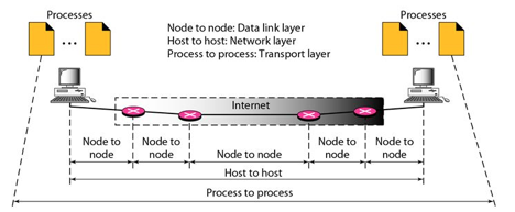
Fig 2: Process to process delivery
Client/Server Paradigm
Process-to-process communication can be obtained in a variety of methods, the most prevalent of which is through the client/server paradigm. On the local-host, a process is referred to as a client. Typically, the remote host is required to provide services to the processes, which is referred to as server. Both processes have the same name (client and server). A socket address is a combination of an IP address and a port number that defines a process and a host.
Multiplexing and Demultiplexing
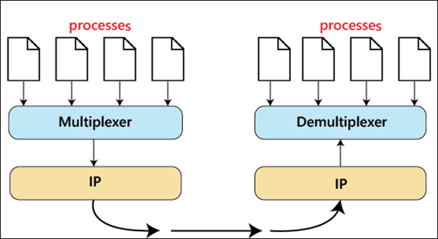
● Multiplexing: Multiple processes might occur at the sender site, and those activities are required to send packets. It's a method for combining numerous operations into a single one.
● Demultiplexing: Demultiplexing is a technique that separates multiple processes at the receiver location.
UDP (User Datagram Protocol)
David P Reed came up with UDP in 1980. It's a protocol that doesn't require a connection and is unreliable. This means that this protocol does not establish a connection between the sender and receiver while data is transferred. The receiver does not acknowledge that the data has been received. It transfers the info straight to the recipient. The datagram is the name for a data packet in UDP. UDP does not guarantee that your data will arrive at its intended location. It is not necessary for the data to arrive at the receiver in the same sequence as it was transmitted by the sender.
Transmission Control Protocol
Transmission Control Protocol (TCP) is an acronym for Transmission Control Protocol. It first appeared in 1974. It's a dependable and connection-oriented protocol. Before beginning the communication, it establishes a connection between the source and destination devices. It determines if the data sent from the source device was received by the destination device. It sends the data again if the data received is not in the correct format. Because it employs a handshake and traffic control mechanism, TCP is extremely dependable. Data is received in the same manner that the sender sends it in while using the TCP protocol. HTTP, HTTPS, Telnet, FTP, SMTP, and other TCP protocol services are used in our daily lives.
Q13) What is the difference between TCP and UDP?
A13) Difference between UDP and TCP
UDP | TCP |
UDP stands for User Datagram Protocol. | TCP stands for Transmission Control Protocol. |
UDP sends the data directly to the destination device. | TCP establishes a connection between the devices before transmitting the data. |
It is a connectionless protocol. | It is a connection-oriented protocol. |
UDP is faster than the TCP protocol. | TCP is slower than the UDP protocol. |
It is an unreliable protocol. | It is a reliable protocol. |
It does not have a sequence number of each byte. | It has a sequence number of each byte. |
Q14) What do you mean by open loop?
A14) Policies are used in open-loop congestion control to prevent congestion before it occurs. Congestion control is performed by either the source or the destination in these systems.
a. Retransmission Policy
Sometimes retransmission is unavoidable. If the sender believes a packet has been lost or corrupted, the packet must be resent. In general, retransmission may cause network congestion. A good retransmission policy, on the other hand, can prevent congestion. The retransmission strategy and timers must be configured in such a way that they maximize efficiency while avoiding congestion. TCP's retransmission strategy, for example (described below), is meant to avoid or alleviate congestion.
b. Window Policy
Congestion may be influenced by the type of window used by the sender. For congestion control, the Selective Repeat window outperforms the Go-Back-N window. When the timer for a packet times out in the Go-Back-N window, numerous packets may be resent, even if some may have arrived safely at the recipient. This duplication could exacerbate the bottleneck. The Selective Repeat window, on the other hand, attempts to send only the lost or damaged packets.
c. Acknowledgment Policy
Congestion may be influenced by the receiver's acknowledgment policy. If the receiver does not acknowledge every packet it gets, the sender will be slowed and congestion will be avoided. In this scenario, several ways are applied. Only when a packet needs to be sent or when a particular timer expires can a receiver send an acknowledgment. Only N packets may be acknowledged at a time by a receiver. We need to understand that acknowledgements are part of a network's burden. Sending fewer acknowledgements reduces the amount of traffic on the network.
d. Discarding Policy
Routers with a good discarding policy can prevent congestion while not jeopardising the integrity of the transmission. In audio transmission, for example, if the policy is to discard less sensitive packets when congestion is expected, the sound quality is kept while congestion is avoided or alleviated.
e. Admission Policy
In virtual-circuit networks, an admission policy, which is a quality-of-service mechanism, can also reduce congestion. Before admitting a flow to the network, switches in a flow verify its resource requirements. If the network is congested or there is a chance of future congestion, a router can refuse to make a virtual circuit connection.
Q15) Write about closed loop?
A15) Closed-loop congestion control systems aim to reduce traffic congestion after it has occurred. Different methods have used a variety of mechanisms.
a. Backpressure
Backpressure is a congestion control technique in which a congested node stops receiving data from the upstream node or nodes it is connected to. As a result, the upstream node or nodes may become overburdened, and they may reject data from their upstream node or nodes. And so forth. Backpressure is a type of node-to-node congestion control that begins at a node and spreads to the source in the reverse direction of data flow. Only virtual circuit networks with each node knowing the upstream node from which a data flow is emanating can use the backpressure technique. Backpressure is depicted in the diagram.

Fig 5: Backpressure method
The incoming data for Node III in the diagram is greater than it can manage. It discards a few packets from its input buffer and tells node II to slow down. Node II, in turn, may be congested as a result of the data output flow being slowed. When node II becomes crowded, it signals node I to slow down, which may cause congestion. If this is the case, node I will advise the data source to slow down. This, in turn, relieves congestion over time. This, in turn, relieves congestion over time. To clear the congestion, the pressure on node III is shifted backwards to the source.
b. Choke Packet
A choke packet is a message delivered by a node to the source informing it that the network is congested. The backpressure and choke packet approaches differ from one another. The alert is sent from one node to its upstream node under backpressure, albeit it may finally reach the source station. The choke packet approach sends a direct warning to the source station from the router that has encountered congestion. The intermediary nodes that the packet passed through are not notified. In ICMP, we've seen an example of this form of control. When an Internet router receives a large number of IP datagrams, it may discard some of them, but it notifies the source host via an ICMP source quench message. The warning message is sent directly to the source station, bypassing the intermediate routers, with no action taken. A choke packet is seen in the diagram.

Fig 6: Choke packet
c. Implicit Signaling
There is no communication between the congested node or nodes and the source in implicit signaling. Other signs lead the source to believe that there is congestion somewhere in the network. One assumption is that the network is congested when a source sends multiple packets and receives no acknowledgement for a long time. The lack of an acknowledgement is viewed as network congestion, and the source should slow down.
d. Explicit Signaling
When a node encounters congestion, it can transmit an explicit signal to the source or destination. The explicit signaling approach, on the other hand, is not the same as the choke packet method. A separate packet is used for this purpose in the choke packet approach; in the explicit signaling method, the signal is included in the data packets. Explicit signaling can occur in either the forward or backward direction, as we'll see in Frame Relay congestion control.
i. Backward Signaling
In a packet going in the opposite direction of the congestion, a bit can be set. This bit can alert the source that there is a bottleneck and that it should slow down to minimize packet loss.
Ii. Forward Signaling
In a packet traveling in the direction of congestion, a bit can be set. This bit can alert the destination to the fact that there is a traffic jam. In this instance, the receiver can utilize measures to reduce congestion, such as slowing down acknowledgments.