Unit - 2
Physical Layer
Q1) Write the types of error?
A1) When data is sent from one computer to another, the system cannot guarantee that the data received by the device is similar to the data sent by the other device. When the message received at the recipient end differs from the message sent, it is called an error.
Types of Error
● Single - bit error: Just one bit in the obtained frame has been corrupted, i.e. it has been modified from 0 to 1 or 1 to 0.

Fig 1: Single-bit error
● Burst error: Burst Error occurs when two or more bits are shifted from 0 to 1 or 1 to 0. More than one consecutive bit in the received frame was corrupted.

Fig 2: Burst error
Q2) Define framing?
A2) Data transmission at the physical layer entails the synchronized transmission of bits from the source to the destination. These bits are packed into frames by the data link layer.
The Data-link Layer encapsulates the packets from the Network Layer into frames. If the frame size gets too big, the packet can be split up into smaller frames. Flow control and error control are more effective with smaller frames.
Then it sends each frame to the hardware bit by bit. The data link layer at the receiver's end collects signals from hardware and assembles them into frames.
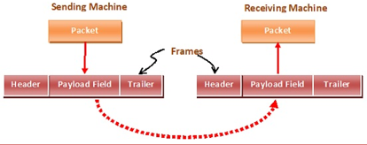
Fig 3: Framing
Parts of the Framing
A frame has the following pieces −
● Frame header: It includes the frame's source and destination addresses.
● Payload field: It holds the message that will be sent.
● Trailer: It includes the bits for error detection and correction.
● Field: It denotes the start and end of the frame.

Fig 4: Parts of frames
Q3) Write the types of framing?
A3) Types of Framing
There are two styles of framing: fixed sized framing and variable sized framing.
Fixed - size framing: The frame size is set in this case, so the frame length serves as a delimiter. As a result, no additional boundary bits are required to define the start and end of the frame.
Variable - size framing: The size of each frame to be transmitted can differ in this case. As a result, additional mechanisms are held to indicate the end of one frame and the start of the next.
It's a protocol that's used in local area networks.
In variable-sized framing, there are two ways to describe frame delimiters.
Length Field: The size of the frame is determined by a length field in this case. Ethernet makes use of it (IEEE 802.3).
End Delimiter: To decide the size of the frame, a pattern is used as a delimiter. Token Rings make use of it. If the pattern appears in the message, there are two options for dealing with the case.
● Byte - stuffing: To distinguish the message from the delimiter, a byte is crammed into it. Character-oriented framing is another term for this.
● Bit - stuffing: To distinguish the message from the delimiter, a pattern of bits of arbitrary duration is stuffed into it. This is often referred to as bit-oriented framing.
Q4) Define stop and wait ARQ?
A4) Stop-and-wait In the event of broken or lost frames, ARQ is a technique for retransmitting the data.
This approach works on the idea that the sender will not transmit the next frame until the previous frame has been acknowledged.
Step 1: If a frame is destroyed during transmission in a noisy channel, the receiver will detect it using the checksum.
Step 2: If a damaged frame is received, it will be discarded, and the transmitter will retransmit the frame whenever a proper acknowledgement is received.
Step 3: If the acknowledgement frame is missing, the data link layer on 'A' will eventually time out. It assumes that its data frame was lost or corrupted because it did not receive an ACK and sends the frame containing packet 1 again. Because this duplicate frame also arrives on 'B' at the data link layer, a portion of the file will be duplicated, and the protocol will be considered unsuccessful.
Step 4: In the message header, assign a sequence number to remedy this problem.
Step 5: Because only the message is transmitted at any one moment, the receiver examines the sequence number to see if the message is a duplicate.
Step 6: To preserve the relationship between the broadcast message and its ACK/ NAK, the sending and receiving stations simply need a 1-bit alternating sequence of '0' or'1'.
Step 7: A modulo-2 numbering scheme is utilized, with frames labeled '0' or '1' and positive acknowledgements of the type ACK 0 and ACK 1.
The normal operation of the Stop & Wait ARQ is as follows:
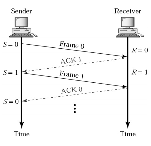
The Stop & Wait ARQ with Lost Frame looks like this:

Q5) Write the characteristics of stop and wait ARQ?
A5) Characteristics
The retransmission must have four characteristics:
● Until the acknowledgement is received, the sending device stores a duplicate of the last broadcast frame. If the frame is not received correctly, the sender might retransmit the data by keeping the copy.
● The data and ACK frames are both numbered 0 and 1 so that they can be distinguished from one another. If data 1 frame acknowledges data 0 frame, it signifies that data 0 frame arrived correctly and that data 1 frame is on its way.
● If the final transmitted frame contains an error, the receiver sends the NAK frame, which has no number. The sender retransmits the data after receiving the NAK frame.
● It operates in conjunction with the timer. If the acknowledgement does not arrive within the permitted time, the sender concludes that the frame was lost during transmission and will retransmit it.
Q6) Describe Go-Back-N ARQ?
A6) Go
Go-Back-N ARQ protocol is also known as Go-Back-N Automatic Repeat Request. It is a data link layer protocol that uses a sliding window method. In this, if any frame is corrupted or lost, all subsequent frames have to be sent again.
In Go-Back-N ARQ, N is the sender's window size. Suppose we say that Go-Back-3, which means that the three frames can be sent at a time before expecting the acknowledgment from the receiver.
It uses the principle of protocol pipelining in which the multiple frames can be sent before receiving the acknowledgment of the first frame. If we have five frames and the concept is Go-Back-3, which means that the three frames can be sent, i.e., frame no 1, frame no 2, frame no 3 can be sent before expecting the acknowledgment of frame no 1.
In Go-Back-N ARQ, the frames are numbered sequentially as Go-Back-N ARQ sends the multiple frames at a time that requires the numbering approach to distinguish the frame from another frame, and these numbers are known as the sequential numbers.
The number of frames that can be sent at a time totally depends on the size of the sender's window. So, we can say that 'N' is the number of frames that can be sent at a time before receiving the acknowledgment from the receiver.
If the acknowledgment of a frame is not received within an agreed-upon time period, then all the frames available in the current window will be retransmitted. Suppose we have sent the frame no 5, but we didn't receive the acknowledgment of frame no 5, and the current window is holding three frames, then these three frames will be retransmitted.
The sequence number of the outbound frames depends upon the size of the sender's window. Suppose the sender's window size is 2, and we have ten frames to send, then the sequence numbers will not be 1,2,3,4,5,6,7,8,9,10. Let's understand through an example.
● N is the sender's window size.
● If the size of the sender's window is 4 then the sequence number will be 0,1,2,3,0,1,2,3,0,1,2, and so on.
The number of bits in the sequence number is 2 to generate the binary sequence 00,01,10,11.
Q7) Explain the working of G0-back-N ARQ?
A7) Working of Go-Back-N ARQ
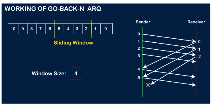
Suppose there are a sender and a receiver, and let's assume that there are 11 frames to be sent. These frames are represented as 0,1,2,3,4,5,6,7,8,9,10, and these are the sequence numbers of the frames. Mainly, the sequence number is decided by the sender's window size. But, for the better understanding, we took the running sequence numbers, i.e., 0,1,2,3,4,5,6,7,8,9,10. Let's consider the window size as 4, which means that the four frames can be sent at a time before expecting the acknowledgment of the first frame.
Step 1: Firstly, the sender will send the first four frames to the receiver, i.e., 0,1,2,3, and now the sender is expected to receive the acknowledgment of the 0th frame.
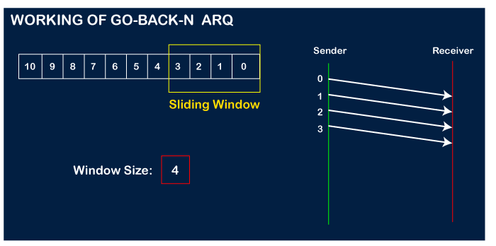
Let's assume that the receiver has sent the acknowledgment for the 0 frame, and the receiver has successfully received it.

The sender will then send the next frame, i.e., 4, and the window slides containing four frames (1,2,3,4).
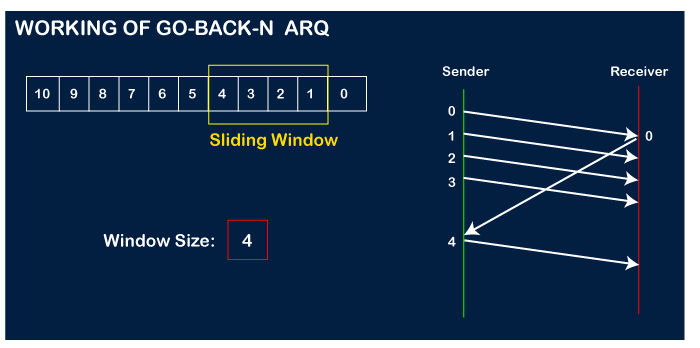
The receiver will then send the acknowledgment for the frame no 1. After receiving the acknowledgment, the sender will send the next frame, i.e., frame no 5, and the window will slide having four frames (2,3,4,5).
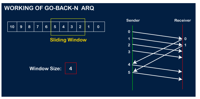
Now, let's assume that the receiver is not acknowledging the frame no 2, either the frame is lost, or the acknowledgment is lost. Instead of sending the frame no 6, the sender Go-Back to 2, which is the first frame of the current window, retransmits all the frames in the current window, i.e., 2,3,4,5.

Q8) Write the difference between Go-Back-N ARQ and Selective Repeat ARQ?
A8) Difference between the Go-Back-N ARQ and Selective Repeat ARQ
Go-Back-N ARQ | Selective Repeat ARQ |
If a frame is corrupted or lost in it,all subsequent frames have to be sent again. | In this, only the frame is sent again, which is corrupted or lost. |
If it has a high error rate,it wastes a lot of bandwidth. | There is a loss of low bandwidth. |
It is less complex. | It is more complex because it has to do sorting and searching as well. And it also requires more storage. |
It does not require sorting. | In this, sorting is done to get the frames in the correct order. |
It does not require searching. | The search operation is performed in it. |
It is used more. | It is used less because it is more complex. |
Q9) Explain selective repeat ARQ?
A9) Selective Repeat ARQ
Selective Repeat ARQ is also known as the Selective Repeat Automatic Repeat Request. It is a data link layer protocol that uses a sliding window method. The Go-back-N ARQ protocol works well if it has fewer errors. But if there is a lot of error in the frame, lots of bandwidth loss in sending the frames again. So, we use the Selective Repeat ARQ protocol. In this protocol, the size of the sender window is always equal to the size of the receiver window. The size of the sliding window is always greater than 1.
If the receiver receives a corrupt frame, it does not directly discard it. It sends a negative acknowledgment to the sender. The sender sends that frame again as soon as on the receiving negative acknowledgment. There is no waiting for any time-out to send that frame. The design of the Selective Repeat ARQ protocol is shown below.
Selective repeat protocol, also called Selective Repeat ARQ (Automatic Repeat reQuest), is a data link layer protocol that uses sliding window method for reliable delivery of data frames. Here, only the erroneous or lost frames are retransmitted, while the good frames are received and buffered.
It uses two windows of equal size: a sending window that stores the frames to be sent and a receiving window that stores the frames receive by the receiver. The size is half the maximum sequence number of the frame. For example, if the sequence number is from 0 – 15, the window size will be 8.
Working Principle
Selective Repeat protocol provides for sending multiple frames depending upon the availability of frames in the sending window, even if it does not receive acknowledgement for any frame in the interim. The maximum number of frames that can be sent depends upon the size of the sending window.
The receiver records the sequence number of the earliest incorrect or un-received frame. It then fills the receiving window with the subsequent frames that it has received. It sends the sequence number of the missing frame along with every acknowledgement frame.
The sender continues to send frames that are in its sending window. Once, it has sent all the frames in the window, it retransmits the frame whose sequence number is given by the acknowledgements. It then continues sending the other frames.
Q10) Write the algorithm for sender site of selective repeat protocol?
A10) Sender Site Algorithm of Selective Repeat Protocol
Begin
Frame s; //s denotes frame to be sent
Frame t; //t is temporary frame
S_window = power(2,m-1); //Assign maximum window size
SeqFirst = 0; // Sequence number of first frame in window
SeqN = 0; // Sequence number of Nth frame window
While (true) //check repeatedly
Do
Wait_For_Event(); //wait for availability of packet
If ( Event(Request_For_Transfer)) then
//check if window is full
If (SeqN–SeqFirst >= S_window) then
DoNothing();
End if;
Get_Data_From_Network_Layer();
s = Make_Frame();
s.seq = SeqN;
Store_Copy_Frame(s);
Send_Frame(s);
Start_Timer(s);
SeqN = SeqN + 1;
End if;
If ( Event(Frame_Arrival) then
r = Receive_Acknowledgement();
//Resend frame whose sequence number is with ACK
If ( r.type = NAK) then
If ( NAK_No > SeqFirst && NAK_No < SeqN ) then
Retransmit( s.seq(NAK_No));
Start_Timer(s);
End if
//Remove frames from sending window with positive ACK
Else if ( r.type = ACK ) then
Remove_Frame(s.seq(SeqFirst));
Stop_Timer(s);
SeqFirst = SeqFirst + 1;
End if
End if
// Resend frame if acknowledgement haven’t been received
If ( Event(Time_Out)) then
Start_Timer(s);
Retransmit_Frame(s);
End if
End
Receiver Site Algorithm of Selective Repeat Protocol
Begin
Frame f;
RSeqNo = 0; // Initialise sequence number of expected frame
NAKsent = false;
ACK = false;
For each slot in receive_window
Mark(slot)=false;
While (true) //check repeatedly
Do
Wait_For_Event(); //wait for arrival of frame
If ( Event(Frame_Arrival) then
Receive_Frame_From_Physical_Layer();
If ( Corrupted ( f.SeqNo ) AND NAKsent = false) then
SendNAK(f.SeqNo);
NAKsent = true;
End if
If ( f.SeqNo != RSeqNo AND NAKsent = false ) then
SendNAK(f.SeqNo);
NAKsent = true;
If ( f.SeqNo is in receive_window ) then
If ( Mark(RSeqNo) = false ) then
Store_frame(f.SeqNo);
Mark(RSeqNo) = true;
End if
End if
Else
While ( Mark(RSeqNo))
Extract_Data(RSeqNo);
Deliver_Data_To_Network_Layer();
RSeqNo = RSeqNo + 1;
Send_ACK(RSeqNo);
End while
End if
End if
End while
End
Q11) Describe the error detection methods?
A11) Error Detecting Technique
There are three major methods for identifying frame errors:
- Parity check
- Checksum
- Cyclic Redundancy check
Parity Check
The parity check is performed by adding an extra bit to the data called the parity bit, which results in a number of 1s that is either even in even parity or odd in odd parity.
The sender counts the number of 1s in a frame and adds the parity bit in the following way when making it.
● Even parity: The parity bit value is 0 if the number of 1s is even. The parity bit value is 1 if the number of 1s is odd.
● Odd parity: The parity bit value is 0 if the number of 1s is odd. The parity bit value is 1 if the number of 1s is even.
The receiver counts the number of 1s in a frame as it receives it. If the count of 1s is even in an even parity search, the frame is accepted; otherwise, it is rejected. For odd parity search, a similar rule is used. The parity check is only good for detecting single bit errors.
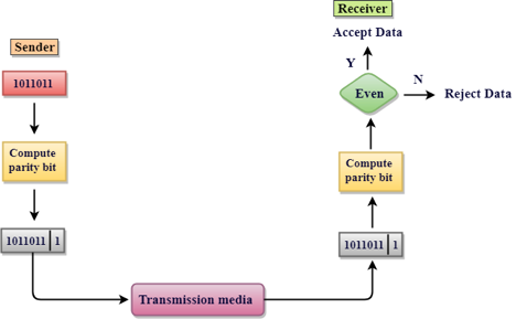
Fig 5: Parity check
Checksum
The following procedure is used in this error detection scheme:
● Data is divided into frames or segments of a predetermined dimension.
● To get the sum, the sender adds the segments using 1's complement arithmetic. It then adds the sums together to get the checksum, which it sends along with the data frames.
● To get the number, the receiver adds the incoming segments and the checksum using 1's complement arithmetic, then complements it.
● The obtained frames are approved if the outcome is zero; otherwise, they are discarded.
Cyclic Redundancy Check (CRC)
CRC is a binary division of the data bits being sent by a fixed divisor agreed upon by the communicating machine. Polynomials are used to build the divisor.
Here, the sender divides the data segment by the divisor in binary. The remaining CRC bits are then appended to the end of the data segment. As a consequence, the resulting data unit is divisible by the divisor exactly.
The divisor is used by the receiver to separate the incoming data unit. The data unit is considered to be right and approved if there is no remainder. Otherwise, it's assumed that the data is tainted and will be denied.

Fig 6: CRC
Q12) What are the error correction methods?
A12) Error correction
Techniques for correcting errors determine the exact number of corrupted bits as well as their positions.
There are two main approaches.
- Backward Error Correction: When the receiver finds an error in an incoming frame, it asks the sender to resend it. It's a straightforward procedure. However, it can only be used effectively where retransmission is not costly, such as in fiber optics, and the retransmission time is short in comparison to the application's requirements.
- Forward Error Correction: If the receiver detects an error in the incoming frame, error-correcting code is executed, and the actual frame is produced. This reduces the amount of bandwidth required for retransmission. In real-time systems, it is unavoidable. If there are so many faults, however, the frames must be present.
The four most popular error correction codes are as follows:
● Hamming Codes
● Binary Convolution Code
● Reed – Solomon Code
● Low-Density Parity-Check Code
Hamming Code
Algorithm of hamming code
● An information of 'd' bits are added to the redundant bits 'r' to form d+r.
● The location of each of the (d+r) digits is assigned a decimal value.
● The 'r' bits are placed in the positions 1,2,.....2k-1.
● At the receiving end, the parity bits are recalculated. The decimal value of the parity bits determines the position of an error.
Q13) Describe the flow control?
A13) Flow control
It's a series of instructions that tells the sender how much data they can send before the recipient becomes overwhelmed. The data is stored on a receiving computer with limited speed and memory.
As a result, before the limits are reached, the receiving system must be able to alert the transmitting device to temporarily halt transmission. It necessitates the use of a buffer, which is a memory block used to store data before it is processed.
Consider the case where the sender sends frames faster than the recipient can receive them. If the sender continues to send frames at a high pace, the receiver will eventually become overwhelmed and begin to lose frames. Introducing flow control may be the solution to this issue. Most flow control protocols provide a feedback mechanism that notifies the sender when the next frame should be transmitted.
Mechanism for flow control
● Stop and wait
● Sliding window
Stop and Wait
The following transformations are included in this protocol:
● The sender sends a frame and then waits for a response.
● When the receiver receives the frame, it gives the sender an acknowledgment frame.
● The sender recognizes that the recipient is able to consider the next frame after receiving the acknowledgment frame. As a result, it sends the next frame in the queue.
Advantages
The Stop-and-Wait approach is straightforward, as each frame is tested and accepted before sending the next.
Disadvantages
Since each frame must travel all the way to the recipient, and an acknowledgment must travel all the way until the next frame is sent, the stop-and-wait strategy is inefficient. Each frame sent and received consumes the entire connection traversal time.
Sliding Window
By allowing several frames to be transmitted before receiving an acknowledgement, this protocol increases the efficiency of the stop and wait protocol.
The following is a summary of the protocol's working principle:
● Both the sender and the receiver have windows, which are finite sized buffers. Depending on the buffer capacity, the sender and receiver agree on the number of frames to transmit.
● The sender sends a series of frames without waiting for an acknowledgement. It waits for acknowledgement after its sending window has been filled. It advances the window and transmits the next frames based on the amount of acknowledgements received.
Sender Window
The sender window comprises n-1 frames at the start of a transmission, and when they are sent out, the left boundary shifts inward, shrinking the window's dimension.
The sender window extends to the number equal to the number of frames acknowledged by ACK until the ACK has arrived.
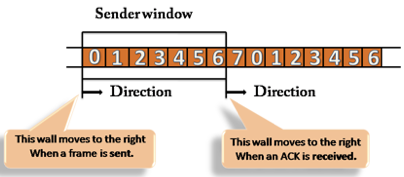
Fig 7: Sender window
Receiver Window
The receiver window does not contain n frames at the start of transmission, but it does contain n-1 spaces for frames. The size of the window shrinks when the new frame arrives. The receiver window indicates the maximum number of frames that can be sent before an ACK is sent, not the number of frames received.

Fig 8: Receiver window
Q14) Define HDLC?
A!4) HDLC
HDLC stands for High-level Data Link Control, a transmission mechanism for data communications that is utilized at the data link layer (layer 2) of the OSI seven-layer model. The HDLC protocol embeds data frames with information that allows devices to manage data flow and remedy faults. HDLC is an ISO standard that evolved from the IBM-proposed Synchronous Data Link Control (SDLC) standard in the 1970s. NRM HDLC (also known as SDLC)
HDLC is a bit-oriented protocol that can communicate in half-duplex and full-duplex via point-to-point and multipoint links.
One station is labeled primary and the other secondary for any HDLC communications session. One of the following connection modes determines how the primary and secondary stations communicate during a session.
There are three types of stations that can be used with the HDLC protocol to adapt it to different network configurations:
● Primary Station - This station is primarily responsible for data management. When it comes to communication between the primary and secondary stations, the primary station is in charge of connecting and disconnecting the data link. The frames that the primary station sends out are generally referred to as commands.
● Secondary Station - The primary station directs the satellite station's operations. The responses produced by the secondary stations are generally referred to as frames.
● Combined Station - The combination station functions as both a primary and secondary station. Both instructions and responses are issued by the combined station.
Transfer Modes in HDLC
The HDLC protocol has two transfer modes that can be utilized in a variety of configurations. The following are some of them:
● Normal Response Mode(NRM)
● Asynchronous Balanced Mode(ABM)
Normal Response Mode (NRM) - There are two sorts of stations here: a primary station that sends commands and a secondary station that responds to commands received. It can be used for point-to-point and multipoint communication.
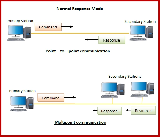
Fig 9: NRM
Asynchronous Balanced Mode (ABM) - The setup is balanced in this case, meaning that each station can both send and receive commands. It can only be used for point-to-point communication.
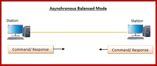
Fig 10: ABM
HDLC Frames
HDLC is a bit-oriented protocol with up to six fields in each frame. The construction changes depending on the frame type. A HDLC frame's fields are as follows:
Flag - It's an 8-bit sequence that indicates the start and end of a frame. The flag's bit pattern is 01111110.
Address - It contains the receiver's address. If the frame is sent by the primary station, it contains the secondary station's address(es) (s). It contains the primary station's address if it is sent by the secondary station. The address field might be anything from a single byte to many bytes long.
Control - It is made up of one or two bytes that carry flow and error control information.
Payload - This is where data from the network layer is sent. Its length varies depending on the network.
FCS − For error detection, it's a 2 byte or 4 byte frame check sequence. CRC is the standard code (cyclic redundancy code)

Fig 11: HDLC frame
Q15) Write the types of HDLC frames?
A15) Types of HDLC Frames
In order to give the flexibility required to handle all of the options available in the modes and Configurations previously discussed. The HDLC distinguishes three types of frames:
Information Frames(I-frames)
These frames are used to convey user data as well as control data relevant to the user data. It is identified as an I-frame if the first bit of the control field is 0.
Supervisory Frames(S-frames)
These frames are solely for the transmission of control data. The frame is designated as S-frame if the first two bits of the control field are 1 and 0.
Unnumbered Frames(U-Frames)
These frames are mostly used for system administration. These frames are utilized by the communicating devices to exchange control information.

Fig 12: Types of HDLC frame