Unit - 3
Point to point protocol
Q1) Write short notes on point to point (PPP)?
A1) Point - to - Point Protocol (PPP) is a communication protocol of the data link layer that is used to transmit multiprotocol data between two directly connected (point-to-point) computers. It is a byte - oriented protocol that is widely used in broadband communications having heavy loads and high speeds. Since it is a data link layer protocol, data is transmitted in frames. It is also known as RFC 1661.
The main services provided by Point - to - Point Protocol are
- Defining the frame format of the data to be transmitted.
- Defining the procedure of establishing link between two points and exchange of data
- Stating the method of encapsulation of network layer data in the frame.
- Stating authentication rules of the communicating devices
- Providing address for network communication.
- Providing connections over multiple links
- Supporting a variety of network layer protocols by providing a range os services
Point - to - Point Protocol is a layered protocol having three components −
Encapsulation Component − It encapsulates the datagram so that it can be transmitted over the specified physical layer.
● Link Control Protocol (LCP) − It is responsible for establishing, configuring, testing, maintaining and terminating links for transmission. It also imparts negotiation for set up of options and use of features by the two endpoints of the links.
● Authentication Protocols (AP) − These protocols authenticate endpoints for use of services. The two authentication protocols of PPP are Password Authentication Protocol (PAP) Challenge Handshake Authentication Protocol (CHAP)
● Network Control Protocols (NCPs) − These protocols are used for negotiating the parameters and facilities for the network layer. For every higher-layer protocol supported by PPP, one NCP is there.
Q2) What do you mean by multiple access protocol?
A2) When a sender and receiver have a dedicated link to transmit data packets, the data link control is enough to handle the channel. Suppose there is no dedicated path to communicate or transfer the data between two devices. In that case, multiple stations access the channel and simultaneously transmit the data over the channel. It may create collisions and cross talk. Hence, the multiple access protocol is required to reduce the collision and avoid crosstalk between the channels.
For example, suppose that there is a classroom full of students. When a teacher asks a question, all the students (small channels) in the class start answering the question at the same time (transferring the data simultaneously). All the students respond at the same time due to which data overlap or data is lost. Therefore it is the responsibility of a teacher (multiple access protocol) to manage the students and give them one answer.
Following are the types of multiple access protocol that is subdivided into the different process as:
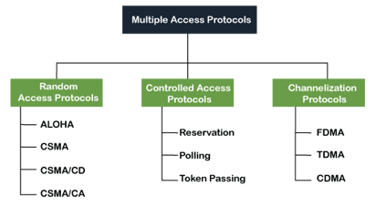
Fig 1: Types of multiple access protocol
A. Random Access Protocol
In this protocol, all the stations have the equal priority to send the data over a channel. In the random access protocol, one or more stations cannot depend on another station nor any station control another station. Depending on the channel's state (idle or busy), each station transmits the data frame. However, if more than one station sends the data over a channel, there may be a collision or data conflict. Due to the collision, the data frame packets may be lost or changed. And hence, it does not receive by the receiver end.
Following are the different methods of random-access protocols for broadcasting frames on the channel.
● Aloha
● CSMA
● CSMA/CD
● CSMA/CA
Q3) Explain pure aloha and slotted aloha?
A3) Pure Aloha
Whenever data is available for sending over a channel at stations, we use Pure Aloha. In pure Aloha, when each station transmits data to a channel without checking whether the channel is idle or not, the chances of collision may occur, and the data frame can be lost. When any station transmits the data frame to a channel, the pure Aloha waits for the receiver's acknowledgment. If it does not acknowledge the receiver ends within the specified time, the station waits for a random amount of time, called the backoff time (Tb). And the station may assume the frame has been lost or destroyed. Therefore, it retransmits the frame until all the data are successfully transmitted to the receiver.
- The total vulnerable time of pure Aloha is 2 * Tfr.
- Maximum throughput occurs when G = 1/ 2 that is 18.4%.
- Successful transmission of data frame is S = G * e ^ - 2 G.
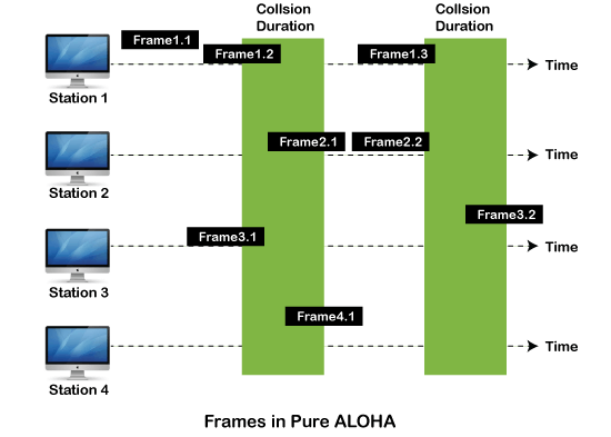
As we can see in the figure above, there are four stations for accessing a shared channel and transmitting data frames. Some frames collide because most stations send their frames at the same time. Only two frames, frame 1.1 and frame 2.2, are successfully transmitted to the receiver end. At the same time, other frames are lost or destroyed. Whenever two frames fall on a shared channel simultaneously, collisions can occur, and both will suffer damage. If the new frame's first bit enters the channel before finishing the last bit of the second frame. Both frames are completely finished, and both stations must retransmit the data frame.
Slotted Aloha
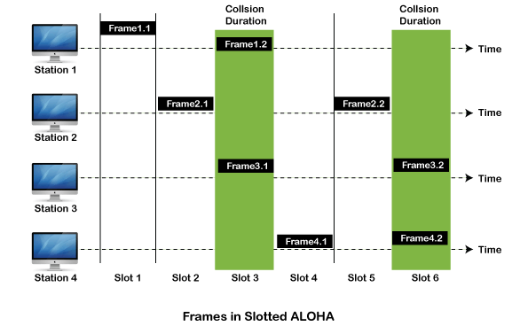
The slotted Aloha is designed to overcome the pure Aloha's efficiency because pure Aloha has a very high possibility of frame hitting. In slotted Aloha, the shared channel is divided into a fixed time interval called slots. So that, if a station wants to send a frame to a shared channel, the frame can only be sent at the beginning of the slot, and only one frame is allowed to be sent to each slot. And if the stations are unable to send data to the beginning of the slot, the station will have to wait until the beginning of the slot for the next time. However, the possibility of a collision remains when trying to send a frame at the beginning of two or more station time slot.
- Maximum throughput occurs in the slotted Aloha when G = 1 that is 37%.
- The probability of successfully transmitting the data frame in the slotted Aloha is S = G * e ^ - 2 G.
- The total vulnerable time required in slotted Aloha is Tfr.
Q4) Write the difference between pure aloha and slotted aloha?
A4) Difference Between Pure Aloha And Slotted Aloha-
Pure Aloha | Slotted Aloha |
Any station can transmit the data at any time. | Any station can transmit the data at the beginning of any time slot. |
The time is continuous and not globally synchronized. | The time is discrete and globally synchronized. |
Vulnerable time in which collision may occur = 2 x Tt | Vulnerable time in which collision may occur = Tt |
Probability of successful transmission of data packet = G x e-2G | Probability of successful transmission of data packet = G x e-G |
Maximum efficiency = 18.4% (Occurs at G = 1/2) | Maximum efficiency = 36.8% ( Occurs at G = 1) |
The main advantage of pure aloha is its simplicity in implementation. | The main advantage of slotted aloha is that it reduces the number of collisions to half and doubles the efficiency of pure aloha. |
Q5) Describe CSMA?
A5) It is a carrier-sense multiple access based on media access protocol to sense the traffic on a channel (idle or busy) before transmitting the data. It means that if the channel is idle, the station can send data to the channel. Otherwise, it must wait until the channel becomes idle. Hence, it reduces the chances of a collision on a transmission medium.
CSMA is a network access mechanism for controlling network access on shared network topologies like Ethernet. Before sending, devices connected to the network cable listen (carrier sense). Devices wait before broadcasting if the channel is in use. Multiple Access (MA) refers to the ability for multiple devices to connect to and share the same network. When the network is clear, all devices have equal access to it.
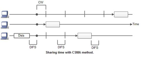
To put it another way, a station that wishes to communicate first "listens" to media communication and then waits for a "quiet" of a certain length of time (called the Distributed Inter Frame Space or DIFS). Following this mandatory interval, the station begins a countdown for a random period.
The collision window is the maximum duration of this countdown (Window Collision, CW). If no equipment talks before the countdown ends, the station will just deliver the gift. If it is surpassed by another station, however, it immediately stops counting and waits for the next moment of stillness. She then picked up where his account countdown had left off. Figure summarizes this information. The random waiting time has the advantage of permitting a statistically equitable allocation of speaking time between the various network equipment while making it rare (but not impossible) that both devices speak at the same time.
The countdown method prevents a station from delaying the delivery of its cargo for too long. It's a little like what happens in a conference room where no master session (and everyone in the world is courteous) expects stillness before speaking, then a few moments before speaking, to give someone else a chance to talk. The time is allotted at random, which means that it is distributed fairly evenly.
CSMA Access Modes
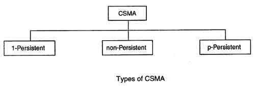
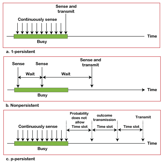
1-Persistent: In the 1-Persistent mode of CSMA that defines each node, first sense the shared channel and if the channel is idle, it immediately sends the data. Else it must wait and keep track of the status of the channel to be idle and broadcast the frame unconditionally as soon as the channel is idle.
Non-Persistent: It is the access mode of CSMA that defines before transmitting the data, each node must sense the channel, and if the channel is inactive, it immediately sends the data. Otherwise, the station must wait for a random time (not continuously), and when the channel is found to be idle, it transmits the frames.
P-Persistent: It is the combination of 1-Persistent and Non-persistent modes. The P-Persistent mode defines that each node senses the channel, and if the channel is inactive, it sends a frame with a P probability. If the data is not transmitted, it waits for a (q = 1-p probability) random time and resumes the frame with the next time slot.
O- Persistent: It is an O-persistent method that defines the superiority of the station before the transmission of the frame on the shared channel. If it is found that the channel is inactive, each station waits for its turn to retransmit the data.
Q6) Illustrate CSMA/CA and CSMA/CD?
A6) CSMA/ CD
It is a carrier sense multiple access/ collision detection network protocol to transmit data frames. The CSMA/CD protocol works with a medium access control layer. Therefore, it first senses the shared channel before broadcasting the frames, and if the channel is idle, it transmits a frame to check whether the transmission was successful. If the frame is successfully received, the station sends another frame. If any collision is detected in the CSMA/CD, the station sends a jam/ stop signal to the shared channel to terminate data transmission. After that, it waits for a random time before sending a frame to a channel.
CSMA/ CA
It is a carrier sense multiple access/collision avoidance network protocol for carrier transmission of data frames. It is a protocol that works with a medium access control layer. When a data frame is sent to a channel, it receives an acknowledgment to check whether the channel is clear. If the station receives only a single (own) acknowledgment, that means the data frame has been successfully transmitted to the receiver. But if it gets two signals (its own and one more in which the collision of frames), a collision of the frame occurs in the shared channel. Detects the collision of the frame when a sender receives an acknowledgment signal.
Following are the methods used in the CSMA/ CA to avoid the collision:
Interframe space: In this method, the station waits for the channel to become idle, and if it gets the channel is idle, it does not immediately send the data. Instead of this, it waits for some time, and this time period is called the Interframe space or IFS. However, the IFS time is often used to define the priority of the station.
Contention window: In the Contention window, the total time is divided into different slots. When the station/ sender is ready to transmit the data frame, it chooses a random slot number of slots as wait time. If the channel is still busy, it does not restart the entire process, except that it restarts the timer only to send data packets when the channel is inactive.
Acknowledgment: In the acknowledgment method, the sender station sends the data frame to the shared channel if the acknowledgment is not received ahead of time.
B. Controlled Access Protocol
It is a method of reducing data frame collision on a shared channel. In the controlled access method, each station interacts and decides to send a data frame by a particular station approved by all other stations. It means that a single station cannot send the data frames unless all other stations are not approved. It has three types of controlled access: Reservation, Polling, and Token Passing.
C. Channelization Protocols
It is a channelization protocol that allows the total usable bandwidth in a shared channel to be shared across multiple stations based on their time, distance and codes. It can access all the stations at the same time to send the data frames to the channel.
Following are the various methods to access the channel based on their time, distance and codes:
- FDMA (Frequency Division Multiple Access)
- TDMA (Time Division Multiple Access)
- CDMA (Code Division Multiple Access)
Q7) Write the difference between CSMA/CA and CSMA/CD?
A7) The following are some of the important differences between CSMA/CA and CSMA/CD.
Sr. No. | Key | CSMA/CA | CSMA/CD |
1 | Effectiveness | CSMA/CA is effective before a collision. | CSMA/CD is effective after a collision. |
2 | Network Type | CSMA/CA is generally used in wireless networks. | CSMA/CD is generally used in wired networks. |
3 | Recovery Time | CSMA/CA minimizes the risk of collision. | CSMA/CD reduces recovery time. |
4 | Conflict Management | CSMA/CA initially transmits the intent to send the data, once an acknowledgment is received, the sender sends the data. | CSMA/CD resends the data frame in case a conflict occurs during transmission. |
5 | IEEE Standards | CSMA/CA is part of the IEEE 802.11 standard. | CSMA/CD is part of the IEEE 802.3 standard. |
6 | Efficiency | CSMA/CA is similar in efficiency as CSMA. | CSMA/CD is more efficient than CSMA. |
Q8) A group of N stations share 100 Kbps slotted ALOHA channel. Each station output a 500 bits frame on an average of 5000 ms even if previous one has not been sent. What is the required value of N?
A8) Throughput Of One Station-
Throughput of each station
= Number of bits sent per second
= 500 bits / 5000 ms
= 500 bits / (5000 x 10-3 sec)
= 100 bits/sec
Throughput Of Slotted Aloha-
Throughput of slotted aloha
= Efficiency x Bandwidth
= 0.368 x 100 Kbps
= 36.8 Kbps
Total Number Of Stations-
Throughput of slotted aloha = Total number of stations x Throughput of each station
Substituting the values, we get-
36.8 Kbps = N x 100 bits/sec
∴ N = 368
Thus, required value of N = 368.
Q9) In a CSMA / CD network running at 1 Gbps over 1 km cable with no repeaters, the signal speed in the cable is 200000 km/sec. What is the minimum frame size?
A9) Given-
Bandwidth = 1 Gbps
Distance = 1 km
Speed = 200000 km/sec
Calculating Propagation Delay-
Propagation delay (Tp)
= Distance / Propagation speed
= 1 km / (200000 km/sec)
= 0.5 x 10⁻⁵ sec
= 5 x 10⁻⁶ sec
Calculating Minimum Frame Size-
Minimum frame size
= 2 x Propagation delay x Bandwidth
= 2 x 5 x 10-6 sec x 109 bits per sec
= 10000 bits
Q10) Suppose nodes A and B are on same 10 Mbps Ethernet segment and the propagation delay between two nodes is 225 bit times. Suppose A and B send frames at t=0, the frames collide then at what time, they finish transmitting a jam signal. Assume a 48 bit jam signal?
A10) Propagation delay (Tp)
= 225 bit times
= 225 bit / 10 Mbps
= 22.5 x 10⁻⁶ sec
= 22.5 μsec
At t = 0,
● Nodes A and B start transmitting their frame.
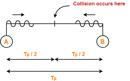
● Since both the stations start simultaneously, so collision occurs at the mid way.
● Time after which collision occurs = Half of propagation delay.
● So, time after which collision occurs = 22.5 μsec / 2 = 11.25 μsec.
At t = 11.25 μsec,
● After collision occurs at t = 11.25 μsec, collided signals start travelling back.
● Collided signals reach the respective nodes after time = Half of propagation delay
● Collided signals reach the respective nodes after time = 22.5 μsec / 2 = 11.25 μsec.
● Thus, at t = 22.5 μsec, collided signals reach the respective nodes.
At t = 22.5 μsec,
● As soon as nodes discover the collision, they immediately release the jam signal.
● Time taken to finish transmitting the jam signal = 48 bit time = 48 bits/ 10 Mbps = 4.8 μsec.
Thus,
Time at which the jam signal is completely transmitted
= 22.5 μsec + 4.8 μsec
= 27.3 μsec or 273 bit times
Q11) A 2 km long broadcast LAN has 107 bps bandwidth and uses CSMA / CD. The signal travels along the wire at 2 x 10⁸ m/sec. What is the minimum packet size that can be used on this network?
● 50 B
● 100 B
● 200 B
● None of the above
A11) Given-
Distance = 2 km
Bandwidth = 107 bps
Speed = 2 x 10⁸ m/sec
Calculating Propagation Delay-
Propagation delay (Tp)
= Distance / Propagation speed
= 2 km / (2 x 10⁸ m/sec)
= 2 x 10³ m / (2 x 10⁸ m/sec)
= 10-5 sec
Calculating Minimum Frame Size-
Minimum frame size
= 2 x Propagation delay x Bandwidth
= 2 x 10-5 sec x 107 bits per sec
= 200 bits or 25 bytes
Thus, Option (D) is correct.
Q12) What is LCP?
A12) LCP
Link Control Protocol (LCP) is a data link layer protocol that is part of the Point-to-Point Protocol (PPP). It is in charge of setting up, configuring, testing, managing, and terminating transmission lines. It also imparts negotiation between the two endpoints of the links for setting up settings and using features.
Working Principle
Prior to establishing connections over the point-to-point link, PPP sends out LCP packets while attempting to communicate. The LCP packets test the communication line to see if it can handle the desired data volume and speed. As a result, it agrees on the data frame's size. It also detects configuration issues and identifies the associated peer. If the LCP accepts the link, it sets up and configures the connection so that communication can begin. If the LCP determines that the link is not functioning properly, it will terminate it.
As a result, LCP's functions can be summarized as follows:
● It verifies the connecting peer's identity. The connection with the peer is then either accepted or rejected.
● It establishes the size of the data frame that will be transmitted.
● It detects configuration issues.
● It checks and maintains the connection.
● If it detects that the link is not functioning properly, it terminates it.
LCP Frame
The Payload field of the PPP frame contains the LCP frame.
The PPP frames' fields are as follows:
● Flag: 1 byte that indicates the start and end of the frame. The flag's bit pattern is 01111110.
● Address: In the case of a broadcast, 1 byte is set to 11111111.
● Control: 1 byte with the value 11000000 set as a constant.
● Protocol: The type of data in the payload field is defined by one or two bytes.
● Payload: The LCP frame, which transports data from the network layer, was contained in this.
● FCS: For error detection, it's a 2 byte or 4 byte frame check sequence. CRC is the standard code (cyclic redundancy code)
The fields of the encapsulated LCP frame are −
● Code - 1 byte that identifies the type of LCP frame.
● ID - 1 byte which is an identifier used to match requests and replies.
● Length - 2 bytes that hold the total length of the LCP frame.
● Information - It carries the data from the network layer.
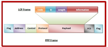
Fig 2: LCP frame
Q13) Define NCP?
A13) NCP
The Network Control Protocol (NCP) is a group of protocols that make up the Point-to-Point Protocol (PPP). PPP is a data link layer protocol for sending multiprotocol data between two computers that are connected directly (point-to-point). Link control protocol (LCP), authentication protocol (AP), and network control protocol (NCP) make up PPP (NCP). NCPs are used to negotiate the network layer's parameters and facilities. One NCP exists for each higher-layer protocol supported by PPP.
The layer in which NCPs work is depicted in the diagram below:
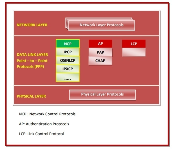
Fig 3: NCP
List of NCPs
Some of the NCPs include:
● Internet Protocol Control Protocol (IPCP) − Over a PPP link, IPCP establishes and configures Internet Protocol (IP). It configures IP addresses on both ends of the PPP link, as well as enabling and disabling IP protocol modules.
● OSI Network Layer Control Protocol (OSINLCP) - OSINLCP is responsible for configuring, enabling, and disabling OSI protocol modules on both ends of the PPP link.
● Internetwork Packet Exchange Control Protocol (IPXCP) − Configuring, enabling, and disabling the Internet Packet Exchange (IPX) modules on both ends of the PPP link are among OSINLCP's responsibilities.
● DECnet Phase IV Control Protocol (DNCP) − This is in charge of setting up and configuring Digital's DNA Phase IV Routing protocol (DECnet Phase IV) modules over a PPP connection.
● NetBIOS Frames Control Protocol (NBFCP) − The NetBIOS Frames (NBF) protocol is a network layer protocol that is not routable. On both ends of the PPP link, NBFCP is in charge of configuring, enabling, and silencing the NBF protocol modules.
● IPv6 Control Protocol (IPV6CP) − IPV6CP is a programme that configures IPv6 addresses. It also allows you to enable and disable IP protocol modules through PPP.
Q14) Explain FDDI?
A14) Fiber Distributed Data Interface is the acronym for Fiber Distributed Data Interface. It's an optical transmission-based high-speed, high-bandwidth network. It's most commonly used as a network backbone for connecting high-end computers (mainframes, minicomputers, and peripherals), as well as LANs connecting high-performance engineering, graphics, and other workstations that require fast data transfer. It supports up to 500 stations on a single network and can transfer data at a rate of 100 Megabits per second.
FDDI was designed to transport information between stations through fiber cables using light pulses, but it can alternatively run on copper using electrical signals. It is relatively expensive to implement, though the cost can be reduced by combining fiber-optic and copper wiring.
Because FDDI networks are made up of two counter-rotating rings, they are extremely dependable. In the case that the primary ring fails, a secondary ring provides an alternative data flow. To route traffic around the problem, FDDI stations add this auxiliary ring into the data line. FDDI with token passing and a ring topology. In the form of a token ring over optical fiber, it is a cutting-edge technology. FDDI was created for two main reasons: to support and help extend the capabilities of older LANs like Ethernet and Token Ring, as well as to provide a stable infrastructure for enterprises, allowing them to move even mission-critical applications to networks.

Fig 4: FDDI
FDDI Features
In terms of fault-tolerance and integrated network management features, FDDI is an effective network topology. FDDI guarantees excellent aggregated throughput rates, even in large and high-traffic networks, because to its deterministic access mechanisms. FDDI may be simply implemented as a robust backbone to current network topologies (such as Ethernet and Token Ring) to solve severe network bottlenecks in LANs.
The following features are available with FDDI:
● Broadband and high transmission speeds (100 Mbps).
● A real throughput rate of approximately 95 Mbps is expected (20 stations).
● Extensive expansions (max. 100 km).
● Extremely long node-to-node distance (2km using multimode fiber, 40 km using single mode fiber).
● Fiber and copper media are both supported.
● Easier to keep up with.
● Compatible with a variety of operating systems and standards-based components.
Frame Format
As indicated in the diagram, the frame format of FDDI is identical to that of token bus.
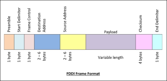
Fig 5: Frame format
An FDDI frame's fields are as follows:
● Preamble - 1 byte for synchronization.
● Start Delimiter - 1 byte that marks the beginning of the frame.
● Frame Control - A single byte that indicates whether the frame is a data or control frame.
● Destination Address - 2-6 bytes that specifies address of destination station.
● Source Address - 2-6 bytes that specifies address of source station.
● Payload - A variable length field that carries the data from the network layer.
● Checksum - 4 bytes frame check sequence for error detection.
● End Delimiter - 1 byte that marks the end of the frame.
Q15) What do you mean by token bus?
A15) The Token Bus (IEEE 802.4) is a standard for deploying token ring in LANs over a virtual ring. The physical medium uses coaxial cables and has a bus or tree architecture. The nodes/stations form a virtual ring, and the token is transmitted from one node to the next in a sequence along the virtual ring. Each node knows the address of the station before it and the station after it. When a station has the token, it can only broadcast data. The token bus works in a similar way as the Token Ring.
Token bus protocols, as opposed to Ethernet's baseband transmission mechanism, are classified by the IEEE 802.4 Committee as broadband computer networks. The token bus is a linear or tree-shape cable to which the stations are connected physically.
The computer network's topology can contain clusters of workstations connected by long trunk lines. The stations are arranged in a ring logically. The network has both a bus and a star topology because these workstations branch from hubs in a star layout. The token bus architecture is ideal for groups of users that are separated by a significant distance. Using a bus architecture, IEEE 802.4 token bus networks are built with 75-ohm coaxial wire. The 802.4 standard's broadband capabilities allow transmission over several channels at the same time.
The highest-numbered station may send the first frame when the logical ring is initialized. Following the numeric sequence of the station addresses, tokens and data frames are sent from one station to the next. As a result, rather than following a physical ring, the token follows a logical ring. The token is returned to the first station by the last station in numerical sequence. The token does not adhere to the physical order of workstation cable installation. Station 1 might be on one end of the cable, station 2 on the other, and station 3 somewhere in the middle.
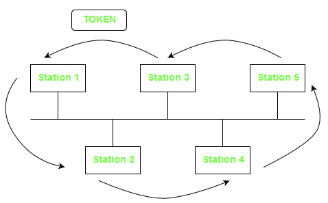
Fig 6: Token bus
Frame Format of Token Bus

Fig 7: Frame format
● Preamble – It's used to synchronize bits. It's a one-byte field.
● Start Delimiter – The start of frame is marked by these bits. It's a one-byte field.
● Frame Control – The type of frame – data frame or control frame – is specified in this field. It's a one-byte field.
● Destination Address – The destination address is stored in this field. It's a 2-to-6-byte field.
● Source Address – The source address is stored in this field. It's a 2-to-6-byte field.
● Data – If 2 byte addresses are utilized, the field can be up to 8182 bytes, whereas 6 byte addresses can be up to 8174 bytes.
● Checksum – The checksum bits in this field are used to detect mistakes in the sent data. It's a four-byte field.
● End Delimiter – This field marks the end of the frame. It is 1 byte field.
Q16) Write the difference between token bus and token ring?
A16) Difference between token bus and token ring
Token Ring | Token Bus |
The token is passed through the coaxial cable network and the physical ring formed by the stations. | The token is passed around a LAN's virtual ring of connected stations. |
Ring topology, or star topology, is used to connect the stations.. | The bus or tree topology that connects the stations is the underlying topology. |
It is defined by IEEE 802.5 standard. | It is defined by IEEE 802.4 standard. |
Here you may calculate the maximum time a token will take to reach a station. | The time it takes to transfer tokens cannot be calculated. |
Q17) What do you mean by reservation?
A17) Reservation protocols are a type of protocol in which stations that want to send data publicize themselves before sending it. These protocols operate at the OSI model's medium access control (MAC) and transport layers.
Prior to transmission, these protocols have a contention period. Each station broadcasts their demand for transmission during the contention period. Following each station's announcement, one of them is assigned network resources depending on any agreed-upon criteria. All collisions are eliminated since each station has complete information of whether or not every other station intends to transmit before actual transmission.
A situation with five stations and a five-slot reservation frame is depicted in the diagram below. Only stations 1, 3, and 4 have made bookings for the first interval. Only station 1 has made a reservation for the second period.

Fig 8: Reservation frame
Examples of Reservation Protocols
The two most well-known reservation protocols are
● Bitmap Protocol is a MAC layer protocol that works with bits.
● The Resource Reservation Protocol (RSVP) is a transport layer protocol.
Bit – Map Protocol
The contention period is divided into N slots in this protocol, where N is the total number of stations sharing the channel. A station sets the relevant bit in the slot if it has a frame to send.
Assume there are ten stations. As a result, there will be ten contention slots. Stations 2, 3, 8, and 9 will set the respective slots to 1 if they choose to transmit. The transmission is usually carried out in the sequence of the slot numbers.
Resource Reservation Protocol (RSVP)
RSVP is a transport layer protocol that is used to reserve resources in a computer network in order to access Internet applications with a higher quality of service (QoS). It uses the Internet protocol (IP) to make resource reservations on behalf of the recipient. It's used for both unicasting (sending data from a single source to a single destination) and multicasting (sending data from multiple sources to multiple destinations) (sending data simultaneously to a group of destination computers).
Q18) Define polling?
A18) The polling procedure is analogous to a roll call in class. A controller, like the instructor, sends a message to each node in turn. One serves as the primary station (controller), while the others serve as subsidiary stations. All data must be exchanged through the controller.
The address of the node being selected for access is included in the message sent by the controller. Although all nodes get the message, only the one to which it is directed responds and provides data, if any. If there is no data, a "poll reject" (NAK) message is normally returned. The polling messages have a large overhead, and the controller's reliability is highly dependent.
What was the first thing the teacher did when he or she entered the classroom at your high school or college? Roll call or attendance is the answer. Let's have a look at the two scenarios. When the teacher calls roll number 1 and receives a response if he or she is present, the teacher moves on to the next roll number, say roll number 2, and roll number 2 is absent, the teacher receives no response or a negative reaction. In a computer network, there is a primary station (teacher) and all other stations (students), and the primary station transmits a message to each station. The address of the station chosen for giving access is included in the message sent by the primary station.
The important thing to note is that all nodes receive the message, but only the addressed one reacts by sending data; if the station has no data to broadcast, it sends a message known as Poll Reject or NAK (negative acknowledgment).
However, this system has significant disadvantages, such as the high overhead of polling messages and the great reliance on the primary station's reliability.
We calculate the effectiveness of this strategy in terms of polling time and data transfer time.
Tpoll = time for polling
Tt = time required for transmission of data
So, efficiency = Tt / (Tt + Tpoll)
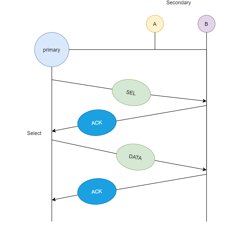
When a primary station needs data, it asks the secondary stations in its channel; this approach is known as polling. The primary station asks station A if it has any data ready for transmission; because A does not have any data queued for transmission, it sends NAK (negative acknowledgement); and then it asks station B; since B has data ready for transmission, it transmits the data and receives acknowledgement from primary station.
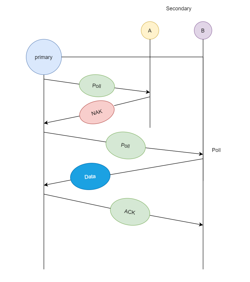
If the primary station wants to send data to the secondary stations, it sends a select message, and if the secondary station accepts the request, it sends back an acknowledgement, after which the primary station transmits the data and receives an acknowledgement.
Q19) Write the difference between CDMA, TDMA, FDMA?
A19) Difference between FDMA, CDMA and TDMA
FDMA | TDMA | CDMA |
FDMA stands for Frequency Division Multiple Access. | TDMA stands for Time Division Multiple Access. | CDMA stands for Code Division Multiple Access. |
In this, sharing of bandwidth among different stations takes place. | In this, only the sharing of time of satellite transponder takes place. | In this, there is sharing of both i.e. bandwidth and time among different stations takes place. |
There is no need of any codeword. | There is no need of any codeword. | Codeword is necessary. |
In this, there is only need of guard bands between the adjacent channels are necessary. | In this, guard time of the adjacent slots are necessary. | In this, both guard bands and guard time are necessary. |
Synchronization is not required. | Synchronization is required. | Synchronization is not required. |
The rate of data is low. | The rate of data is medium. | The rate of data is high. |
Mode of data transfer is continuous signal. | Mode of data transfer is signal in burts. | Mode of data transfer is digital signal. |
It is little flexible. | It is moderate flexible. | It is highly flexible. |
Q20) Describe fast ethernet?
A20) For Ethernet networks that require faster transmission speeds, the Fast Ethernet standard (IEEE 802.3u) was created. With just minor changes to the existing wire topology, this standard doubles the Ethernet speed limit from 10 Mbps to 100 Mbps. Fast Ethernet delivers higher error detection and correction, as well as quicker throughput for video, multimedia, graphics, and Internet surfing.
Fast Ethernet is divided into three categories: 100BASE-TX for use with level 5 UTP cable, 100BASE-FX for use with fiber-optic cable, and 100BASE-T4 for use with level 3 UTP cable. Because of its tight compatibility with the 10BASE-T Ethernet standard, the 100BASE-TX standard has become the most common.
Many decisions must be made by network managers who want to implement Fast Ethernet into an existing system. The number of users who require higher throughput in each network site must be established, as well as which segments of the backbone must be upgraded expressly for 100BASE-T and what hardware is required to connect the 100BASE-T segments with existing 10BASE-T segments. Gigabit Ethernet is a future technology that promises a migration path beyond Fast Ethernet, allowing for considerably faster data transmission speeds in the next generation of networks.
Varieties of Fast Ethernet
100-Base-TX, 100-BASE-FX, and 100-Base-T4 are the most prevalent types of fast Ethernet.
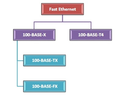
Fig 9: Types of fast ethernet
100-Base-T4
● This has four pairs of Category 3 UTP, two of which are bidirectional and two of which are unidirectional.
● Three pairs can be employed for data transfer in each direction at the same time.
● Each twisted pair can send data at a maximum rate of 25 Mbaud. As a result, the three pairs can manage up to 75Mbaud data.
● It used the 8B/6T (eight binary/six ternary) encoding technique.
100-Base-TX
● Two pairs of unshielded twisted pairs (UTP) category 5 wires or two pairs of shielded twisted pairs (STP) type 1 wires are used. One pair transfers frames from the hub to the device, while the other pair transmits frames from the device to the hub.
● The distance between the hub and the station is limited to 100 meters.
● It has a data rate of 125 megabits per second.
● It employs the MLT-3 coding technique, as well as 4B/5B block coding.
100-BASE-FX
● There are two pairs of optical fibers in this. One pair transfers frames from the hub to the device, while the other pair transmits frames from the device to the hub.
● A maximum distance of 2000 meters exists between the hub and the station.
● It has a data rate of 125 megabits per second.
● It employs the NRZ-I coding method, as well as 4B/5B block coding.