Unit - 5
Protocols
Q1) Define ARP?
A1) Address Resolution Protocol (ARP) is a communication protocol used to find the MAC (Media Access Control) address of a device from its IP address. This protocol is used when a device wants to communicate with another device on a Local Area Network or Ethernet.
Types of ARP
There are four types of Address Resolution Protocol, which is given below:
● Proxy ARP
● Gratuitous ARP
● Reverse ARP (RARP)
● Inverse ARP
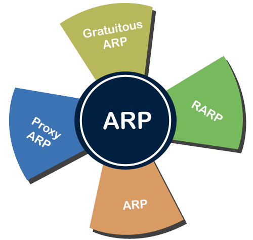
Fig 1: ARP
Proxy ARP - Proxy ARP is a method through which a Layer 3 device may respond to ARP requests for a target that is in a different network from the sender. The Proxy ARP configured router responds to the ARP and maps the MAC address of the router with the target IP address and fools the sender that it is reached at its destination.
At the backend, the proxy router sends its packets to the appropriate destination because the packets contain the necessary information.
Example - If Host A wants to transmit data to Host B, which is on the different network, then Host A sends an ARP request message to receive a MAC address for Host B. The router responds to Host A with its own MAC address pretending itself as a destination. When the data is transmitted to the destination by Host A, it will send to the gateway so that it sends to Host B. This is known as proxy ARP.
Gratuitous ARP - Gratuitous ARP is an ARP request of the host that helps to identify the duplicate IP address. It is a broadcast request for the IP address of the router. If an ARP request is sent by a switch or router to get its IP address and no ARP responses are received, so all other nodes cannot use the IP address allocated to that switch or router. Yet if a router or switch sends an ARP request for its IP address and receives an ARP response, another node uses the IP address allocated to the switch or router.
There are some primary use cases of gratuitous ARP that are given below:
● The gratuitous ARP is used to update the ARP table of other devices.
● It also checks whether the host is using the original IP address or a duplicate one.
Q2) What is RARP?
A2) Reverse ARP (RARP)
It is a networking protocol used by the client system in a local area network (LAN) to request its IPv4 address from the ARP gateway router table. A table is created by the network administrator in the gateway-router that is used to find out the MAC address to the corresponding IP address.
When a new system is set up or any machine that has no memory to store the IP address, then the user has to find the IP address of the device. The device sends a RARP broadcast packet, including its own MAC address in the address field of both the sender and the receiver hardware. A host installed inside of the local network called the RARP-server is prepared to respond to such type of broadcast packet. The RARP server is then trying to locate a mapping table entry in the IP to MAC address. If any entry matches the item in the table, then the RARP server sends the response packet along with the IP address to the requesting computer.
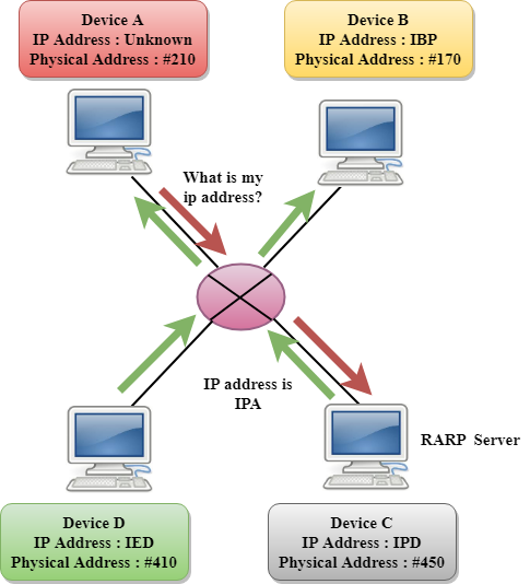
Fig 2: RARP
Inverse ARP (In ARP) - Inverse ARP is inverse of the ARP, and it is used to find the IP addresses of the nodes from the data link layer addresses. These are mainly used for the frame relays, and ATM networks, where Layer 2 virtual circuit addressing are often acquired from Layer 2 signaling. When using these virtual circuits, the relevant Layer 3 addresses are available.
ARP conversions Layer 3 addresses to Layer 2 addresses. However, its opposite address can be defined by In ARP. The In ARP has a similar packet format as ARP, but operational codes are different.
Q3) Explain leaky bucket algorithm?
A3) Let's have a look at how the Leaky Bucket Algorithm works.

Fig 3: Leaky bucket algorithm
The Leaky Bucket Algorithm is primarily responsible for controlling the total volume and rate of traffic supplied to the network.
Step 1: Consider a bucket with a small hole at the bottom into which water is poured at a variable pace, but which leaks at a constant rate.
Step 2 So (as long as there is water in the bucket), the rate at which water leaks is unaffected by the pace at which water is poured into the bucket.
Step 3: If the bucket is full, any more water that enters will pour over the edges and be lost.
Step 4: The same technique was applied to network packets. Consider the fact that data is arriving at varying speeds from the source. Assume a source transmits data at 10 Mbps for 4 seconds. For the next three seconds, there is no data. For 2 seconds, the source transfers data at an 8 Mbps pace. Thus, 68 Mb of data was sent in less than 8 seconds.
As a result, if you employ a leaky bucket technique, the data flow will be 8 Mbps for 9 seconds. As a result, the steady flow is maintained.
Q4) Describe the token bucket algorithm?
A4) One of the strategies for congestion management algorithms is the token bucket algorithm. When there are too many packets in the network, it causes packet delay and packet loss, lowering the system's performance. Congestion is the term for this circumstance.
Congestion management is shared between the network layer and the transport layer. Trying to lessen the burden that the transport layer places on the network is one of the most effective strategies to control congestion. To keep this network running, the network and transport layers must collaborate.
The Token Bucket Algorithm is illustrated graphically as follows:
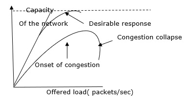
When there is too much traffic, performance suffers significantly.
Token Bucket Algorithm
No matter how busy the network is, the leaky bucket algorithm enforces output patterns at the average rate. To deal with the increased traffic, we'll need a flexible algorithm that won't lose data. The token bucket algorithm is one such method.
Let's take a look at this method one step at a time, as shown below.
Step 1: Tokens are thrown into the bucket f at regular intervals.
Step 2: The bucket can hold a maximum of f.
Step 3: If the packet is ready, a token from the bucket is taken, and the packet is sent.
Step 4 Assume that the packet cannot be forwarded if there is no token in the bucket.
Example
Let's look at an example of the Token Bucket Algorithm.
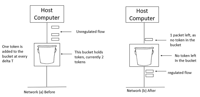
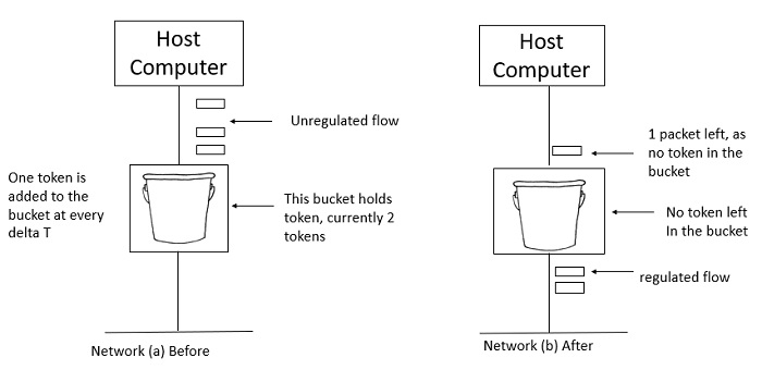
Two tokens are in the bucket in figure (a), and three packets are waiting to be transmitted out of the interface.
Figure (b) shows that two packets have been sent out after two tokens have been consumed, and one packet remains.
The token bucket method is less limiting than the Leaky bucket algorithm, allowing for more traffic. The amount of tokens accessible in the bucket at any given time determines the maximum amount of bustle.
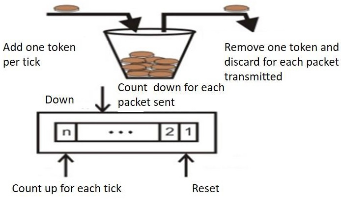
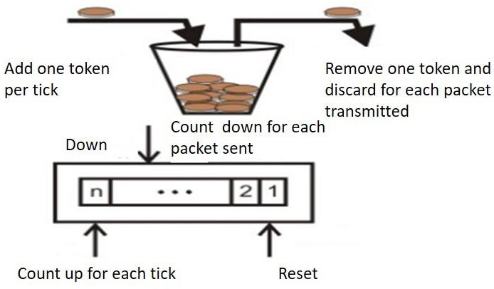
The token bucket technique is simple to construct because the tokens are counted using a variable. The counter is incremented every t seconds and then decremented whenever a packet is sent. When the counter reaches zero, no further packet is sent out.
This is shown in below given diagram −
Q5) Write some advantages of token bucket over leaky bucket?
A5) Some advantage of token Bucket over leaky bucket –
● If the token bucket is full, tokens are discarded rather than packets. Packets are discarded while in a leaky bucket.
● Token Bucket may deliver large bursts at a quicker pace, but a leaky bucket sends packets at the same rate every time.
Q6) What is the difference between a leaky bucket and a token bucket?
A6) Difference between leaky bucket and token bucket
Leaky Bucket | Token Bucket |
When the host has to send a packet , packet is thrown in bucket. | In this leaky bucket holds tokens generated at regular intervals of time. |
Bucket leaks at constant rate | Bucket has maximum capacity. |
Bursty traffic is converted into uniform traffic by leaky bucket. | If there is a ready packet , a token is removed from Bucket and packet is send. |
In practice bucket is a finite queue outputs at finite rate | If there is a no token in bucket, packet can not be send.
|
Q7) Write about ICMP?
A7) The ICMP stands for Internet Control Message Protocol. The ICMP protocol is a network layer protocol that hosts and routers use to notify the sender of IP datagram problems. The echo test/reply method is used by ICMP to determine if the destination is reachable and responding.
ICMP can handle both control and error messages, but its primary purpose is to record errors rather than to fix them. An IP datagram includes the source and destination addresses, but it does not know the address of the previous router it passed through.
As a result, ICMP can only send messages to the source, not to the routers in the immediate vicinity. The sender receives error messages via the ICMP protocol. The errors are returned to the user processes via ICMP messages.
ICMP messages are sent as part of an IP datagram.
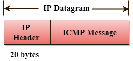
Fig 4: ICMP
Format of ICMP

Fig 5: ICMP format
● The message's form is defined in the first sector.
● The reason for a particular message form is specified in the second sector.
● The checksum field is used to verify the integrity of the entire ICMP message.
Q8) Define IP?
A8) An IP stands for internet protocol. An IP address is assigned to each device connected to a network. Each device uses an IP address for communication. It also behaves as an identifier as this address is used to identify the device on a network. It defines the technical format of the packets. Mainly, both the networks, i.e., IP and TCP, are combined together, so together, they are referred to as TCP/IP. It creates a virtual connection between the source and the destination.
We can also define an IP address as a numeric address assigned to each device on a network. An IP address is assigned to each device so that the device on a network can be identified uniquely. To facilitate the routing of packets, TCP/IP protocol uses a 32-bit logical address known as IPv4(Internet Protocol version 4).
Function:
The internet protocol's main purpose is to provide hosts with addresses, encapsulate data into packet structures, and route data from source to destination through one or more IP networks. The internet protocol provides two main items in order to achieve these functionalities, which are mentioned below.
● Format of IP packet
● IP Addressing system
IP packet
Until an IP packet is sent over the network, it contains two main components: a header and a payload.
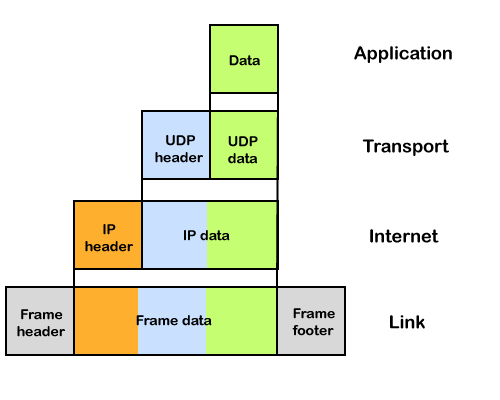
Fig 6: IP packet
An IP header provides a lot of details about the IP packet, such as:
● The source IP address is that of the person who is sending the data.
● IP address of the destination: The destination is a host that collects data from the sender.
● Header length
● Packet length
● TTL (Time to Live) of a packet is the amount of hops that must occur before the packet is discarded.
● The internet protocol's transport protocol, which can be TCP or UDP, is known as the transport protocol.
The IP header contains a total of 14 fields, one of which is optional.
The data to be transported is known as the payload.
Q9) Define voice over IP?
A9) The idea is to use the Internet, with some added capabilities, as a telephone network. This programme allows contact between two parties over the packet-switched Internet, instead of communicating over a circuit-switched network.
Two protocols were developed to deal with this kind of Communication:
SIP(Session Initiation Protocol) and H.323
Session Initiation Protocol (SIP)
The Session Initiation Protocol (SIP) is an application layer protocol established by IETE that creates, manages and terminates a multimedia session (call). Two-party, multiparty, or multicast sessions can be generated using it.
SIP is built to be independent of the underlying transport layer; UDP, TCP, or SCTP may be used.
Message:
SIP is a protocol based on text, and so is HTTP. SIP uses messages, as does HTTP. There are six specified messages.
There is a header and a body in each post. The header consists of several lines which describe the message structure, the capacity of the caller, media type, and so on.

Fig 7: SIP message
● A session with the INVITE message is initialised by the caller.
● The caller sends an ACK message for clarification after the caller answers the call.
● A session is terminated by a BYE call.
● The OPTIONS message asks about the capabilities of a computer.
● The CANCEL message cancels an initialization process which has already begun.
● When the callee is not available, the REGISTER message allows a connection.
Address
A telephone number identifies the sender in a periodic telephone correspondence, and another telephone number identifies the recipient. SIP is very versatile. To distinguish the sender and recipient, an e-mail address, an IP address, a telephone number, and other types of addresses may be used in SIP. The address needs to be in SIP format, though (also called scheme).

Fig 8: SIP address format
Simple sessions
Three modules consist of a basic session using SIP: Establish, Communicating, and terminating.
● Establish a session: It takes a three-way handshake to create a session in SIP. Using UDP, TCP, or SCTP to start contact, the caller sends an INVITE request. She sends a response message if the caller is ready to start the session.
● Communicating: The caller and the callee will communicate by using two temporary ports after the session has been created.
● Terminating the session: With a BYE message sent by either side, the session can be terminated.
Tracking the callee
What happens if there isn't a callee sitting in her terminal? She might be away or at another terminal from her system. If DHCP is being used, she does not even have a set IP address. SIP has a function that seeks the IP address of the terminal at which the callee is sitting (similar to one in DNS). SIP uses the idea of registration to do this monitoring. Some servers are specified by SIP as registrars. A user is registered with at least one registrar server at any time; that server knows the callee's IP address.
The caller should use the e-mail address rather than the IP address in the INVITE message when a caller wants to connect with the caller. The message goes to a server that is a proxy. The proxy server sends a search message (not part of the SIP) to the server of the registrar that registered the call. The proxy server takes the caller's INVITE message and adds the newly discovered IP address of the caller when the proxy server receives a reply message from the registrar's server. This message is sent to the callee, then.
H.323
H.323 is a standard developed by lTV to allow computers (called terminals in H.323) linked to the Internet to communicate to telephones on the public telephone network.
A gateway links the telephone network to the Internet. A gateway is typically a five-layer interface that can convert a message from one stack of protocols to another. The gateway does the very same thing here. It converts a message from the telephone network into an Internet message. As we mentioned in SIP, the gatekeeper server on the local area network plays the role of the registrar server.
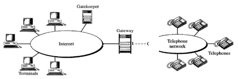
Fig 9: Architecture of H.323
Q10) Explain IPv6?
A10) Internet Protocol version 6 (IPv6) is the latest revision of the Internet Protocol (IP) and the first version of the protocol to be widely deployed. IPv6 was developed by the Internet Engineering Task Force (IETF) to deal with the long-anticipated problem of IPv4 address exhaustion. The Internet has grown exponentially and the address space allowed by IPv4 is saturating.
There is a requirement of protocol which can satisfy the need of future Internet addresses which are expected to grow in an unexpected manner. Using features such as NAT, has made the Internet discontinuous i.e. one part which belongs to intranet, primarily uses private IP addresses; which has to go through a number of mechanisms to reach the other part, the Internet, which is on public IP addresses.
What is IPv6?
IPv4 produces 4 billion addresses, and the developers think that these addresses are enough, but they were wrong. IPv6 is the next generation of IP addresses. The main difference between IPv4 and IPv6 is the address size of IP addresses. The IPv4 is a 32-bit address, whereas IPv6 is a 128-bit hexadecimal address. IPv6 provides a large address space, and it contains a simple header as compared to IPv4.
It provides transition strategies that convert IPv4 into IPv6, and these strategies are as follows:
● Dual stacking: It allows us to have both the versions, i.e., IPv4 and IPv6, on the same device.
● Tunneling: In this approach, all the users have IPv6 and communicate with an IPv4 network to reach IPv6.
● Network Address Translation: The translation allows the communication between the hosts having a different version of IP.
This hexadecimal address contains both numbers and alphabets. Due to the usage of both the numbers and alphabets, IPv6 is capable of producing over 340 undecillion (3.4*1038) addresses.
IPv6 is a 128-bit hexadecimal address made up of 8 sets of 16 bits each, and these 8 sets are separated by a colon. In IPv6, each hexadecimal character represents 4 bits. So, we need to convert 4 bits to a hexadecimal number at a time
The address format of IPv6:

Fig 10: Address format of IPV6
The above diagram shows the address format of IPv4 and IPv6. An IPv4 is a 32-bit decimal address. It contains 4 octets or fields separated by 'dot', and each field is 8-bit in size. The number that each field contains should be in the range of 0-255. Whereas an IPv6 is a 128-bit hexadecimal address. It contains 8 fields separated by a colon, and each field is 16-bit in size.
Q11) Write the difference between IPv6 and IPv4?
A11) Differences between IPv4 and IPv6
| Ipv4 | Ipv6 |
Address length | IPv4 is a 32-bit address. | IPv6 is a 128-bit address. |
Fields | IPv4 is a numeric address that consists of 4 fields which are separated by dot (.). | IPv6 is an alphanumeric address that consists of 8 fields, which are separated by colon. |
Classes | IPv4 has 5 different classes of IP address that includes Class A, Class B, Class C, Class D, and Class E. | IPv6 does not contain classes of IP addresses. |
Number of IP address | IPv4 has a limited number of IP addresses. | IPv6 has a large number of IP addresses. |
VLSM | It supports VLSM (Virtual Length Subnet Mask). Here, VLSM means that Ipv4 converts IP addresses into a subnet of different sizes. | It does not support VLSM. |
Address configuration | It supports manual and DHCP configuration. | It supports manual, DHCP, auto-configuration, and renumbering. |
Encryption and Authentication | It does not provide encryption and authentication. | It provides encryption and authentication. |
Address representation | In IPv4, the IP address is represented in decimal. | In IPv6, the representation of the IP address is hexadecimal. |
Packet flow identification | It does not provide any mechanism for packet flow identification. | It uses a flow label field in the header for the packet flow identification. |
Q12) What is unicast routing?
A12) The majority of internet and intranet traffic, also known as unicast data or unicast traffic, is routed to a specific destination. Unicast routing is the process of sending unicast data via the internet. Because the destination is already known, it is the simplest form of routing. As a result, all the router has to do is check the routing table and forward the packet to the next step.
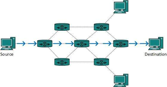
Fig 11: Unicast routing
Unicast packets can be routed using one of two routing protocols:
Distance Vector Routing Protocol
Distance Vector is a straightforward routing technique that bases its decisions on the number of hops between the source and the destination. The best route is one that has the fewest amount of hops. To other routers, each router presents its collection of optimal routes. Finally, all routers construct their network topologies based on peer router ads.
Routing Information Protocol, for example (RIP).
Link State Routing Protocol
The Link State protocol is a little more sophisticated than the Distance Vector protocol. It considers the states of all the routers in a network's links. This technique aids in the creation of a network-wide shared graph. The optimum path for routing is then calculated by all routers. Open Shortest Path First (OSPF) and Intermediate System to Intermediate System (IS-IS) are two examples (ISIS).
Q13) Explain Multicast routing protocol?
A13) Multicast routing is a subset of broadcast routing, with unique characteristics and challenges. Packets are sent to all nodes via broadcast routing, even if they do not want them. However, in Multicast routing, data is only sent to nodes that desire to receive packets.
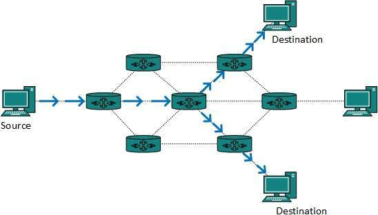
Fig 12: Multicast routing
Multicast routing methods employ trees, i.e. spanning tree, to eliminate loops, whereas Unicast routing protocols use graphs. The shortest path spanning tree is the best tree.
● DVMRP - Distance Vector Multicast Routing Protocol
● MOSPF - Multicast Open Shortest Path First
● CBT - Core Based Tree
● PIM - Protocol independent Multicast
Protocol Independent Multicast (PIM) is currently widely utilised. It comes in two different flavors:
PIM Dense Mode -
Source-based trees are used in this mode. It's employed in high-density environments like LANs.
PIM Sparse Mode -
Shared trees are used in this manner. In a sparse setting, such as a WAN, it is employed.
Q14) Describe choke packets?
A14) Both virtual networks and datagram subnets can benefit from the choke packet strategy. A choke packet is a message delivered by a node to the source informing it that the network is congested. Each router keeps track of its resources and how many of its output lines are in use. The router sends a choke packet to the source anytime resource use exceeds the threshold value defined by the administrator, giving it feedback to minimize traffic. Congestion is not reported to the intermediate nodes via which the packets passed.

In network maintenance and quality management, a choke packet is used to notify a specific node or transmitter that its broadcast traffic is causing network congestion. As a result, the node or transmitter is forced to lower its output rate.
Choke packets are used to control network congestion and flow. The router addresses the source node directly, forcing it to reduce its transmission rate. The source node responds by lowering the sending rate by a certain percentage.
A source quench packet for the Internet Control Message Protocol (ICMP) is a form of choke packet commonly used by routers.
Routers are used in a choke packet's congestion control and recovery approach. Routers often scan the network for anomalies by looking at things like line use, queuing, and buffer length. Routers transmit choke packets to all related segments in the event of congestion to reduce data throughput. Depending on variables such as the size of the congestions, available bandwidth, and buffer size, the source node congesting the network must reduce throughput by a particular factor.
Q15) What is the difference between unicast and multicast?
A15) Difference between Unicast and Multicast
S.No. | Unicast | Multicast |
1. | It has one sender and one receiver. | It has one or more senders and multiple receivers. |
2. | It sends data from one device to single device. | It sent data from one device to multiple devices. |
3. | It works on Single Node Topology. | It works on star, mesh, tree and hybrid topology. |
4. | It does not scale well for streaming media. | It does not scale well across large networks. |
5. | Multiple unicasting utilizes more bandwidth as compared. | It utilizes bandwidth efficiently. |
6. | Web surfing, file transfer is an example of a unicast. | Switch is an example of a multicast device. |
7. | It has one-to-one mapping. | It has one-to-many mapping. |
Unit - 5
Protocols
Q1) Define ARP?
A1) Address Resolution Protocol (ARP) is a communication protocol used to find the MAC (Media Access Control) address of a device from its IP address. This protocol is used when a device wants to communicate with another device on a Local Area Network or Ethernet.
Types of ARP
There are four types of Address Resolution Protocol, which is given below:
● Proxy ARP
● Gratuitous ARP
● Reverse ARP (RARP)
● Inverse ARP
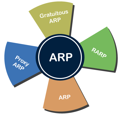
Fig 1: ARP
Proxy ARP - Proxy ARP is a method through which a Layer 3 device may respond to ARP requests for a target that is in a different network from the sender. The Proxy ARP configured router responds to the ARP and maps the MAC address of the router with the target IP address and fools the sender that it is reached at its destination.
At the backend, the proxy router sends its packets to the appropriate destination because the packets contain the necessary information.
Example - If Host A wants to transmit data to Host B, which is on the different network, then Host A sends an ARP request message to receive a MAC address for Host B. The router responds to Host A with its own MAC address pretending itself as a destination. When the data is transmitted to the destination by Host A, it will send to the gateway so that it sends to Host B. This is known as proxy ARP.
Gratuitous ARP - Gratuitous ARP is an ARP request of the host that helps to identify the duplicate IP address. It is a broadcast request for the IP address of the router. If an ARP request is sent by a switch or router to get its IP address and no ARP responses are received, so all other nodes cannot use the IP address allocated to that switch or router. Yet if a router or switch sends an ARP request for its IP address and receives an ARP response, another node uses the IP address allocated to the switch or router.
There are some primary use cases of gratuitous ARP that are given below:
● The gratuitous ARP is used to update the ARP table of other devices.
● It also checks whether the host is using the original IP address or a duplicate one.
Q2) What is RARP?
A2) Reverse ARP (RARP)
It is a networking protocol used by the client system in a local area network (LAN) to request its IPv4 address from the ARP gateway router table. A table is created by the network administrator in the gateway-router that is used to find out the MAC address to the corresponding IP address.
When a new system is set up or any machine that has no memory to store the IP address, then the user has to find the IP address of the device. The device sends a RARP broadcast packet, including its own MAC address in the address field of both the sender and the receiver hardware. A host installed inside of the local network called the RARP-server is prepared to respond to such type of broadcast packet. The RARP server is then trying to locate a mapping table entry in the IP to MAC address. If any entry matches the item in the table, then the RARP server sends the response packet along with the IP address to the requesting computer.
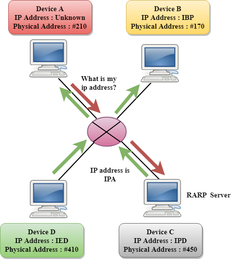
Fig 2: RARP
Inverse ARP (In ARP) - Inverse ARP is inverse of the ARP, and it is used to find the IP addresses of the nodes from the data link layer addresses. These are mainly used for the frame relays, and ATM networks, where Layer 2 virtual circuit addressing are often acquired from Layer 2 signaling. When using these virtual circuits, the relevant Layer 3 addresses are available.
ARP conversions Layer 3 addresses to Layer 2 addresses. However, its opposite address can be defined by In ARP. The In ARP has a similar packet format as ARP, but operational codes are different.
Q3) Explain leaky bucket algorithm?
A3) Let's have a look at how the Leaky Bucket Algorithm works.
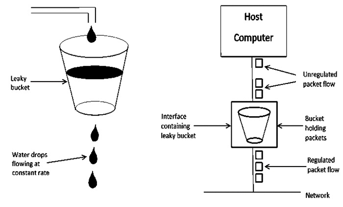
Fig 3: Leaky bucket algorithm
The Leaky Bucket Algorithm is primarily responsible for controlling the total volume and rate of traffic supplied to the network.
Step 1: Consider a bucket with a small hole at the bottom into which water is poured at a variable pace, but which leaks at a constant rate.
Step 2 So (as long as there is water in the bucket), the rate at which water leaks is unaffected by the pace at which water is poured into the bucket.
Step 3: If the bucket is full, any more water that enters will pour over the edges and be lost.
Step 4: The same technique was applied to network packets. Consider the fact that data is arriving at varying speeds from the source. Assume a source transmits data at 10 Mbps for 4 seconds. For the next three seconds, there is no data. For 2 seconds, the source transfers data at an 8 Mbps pace. Thus, 68 Mb of data was sent in less than 8 seconds.
As a result, if you employ a leaky bucket technique, the data flow will be 8 Mbps for 9 seconds. As a result, the steady flow is maintained.
Q4) Describe the token bucket algorithm?
A4) One of the strategies for congestion management algorithms is the token bucket algorithm. When there are too many packets in the network, it causes packet delay and packet loss, lowering the system's performance. Congestion is the term for this circumstance.
Congestion management is shared between the network layer and the transport layer. Trying to lessen the burden that the transport layer places on the network is one of the most effective strategies to control congestion. To keep this network running, the network and transport layers must collaborate.
The Token Bucket Algorithm is illustrated graphically as follows:

When there is too much traffic, performance suffers significantly.
Token Bucket Algorithm
No matter how busy the network is, the leaky bucket algorithm enforces output patterns at the average rate. To deal with the increased traffic, we'll need a flexible algorithm that won't lose data. The token bucket algorithm is one such method.
Let's take a look at this method one step at a time, as shown below.
Step 1: Tokens are thrown into the bucket f at regular intervals.
Step 2: The bucket can hold a maximum of f.
Step 3: If the packet is ready, a token from the bucket is taken, and the packet is sent.
Step 4 Assume that the packet cannot be forwarded if there is no token in the bucket.
Example
Let's look at an example of the Token Bucket Algorithm.
Two tokens are in the bucket in figure (a), and three packets are waiting to be transmitted out of the interface.
Figure (b) shows that two packets have been sent out after two tokens have been consumed, and one packet remains.
The token bucket method is less limiting than the Leaky bucket algorithm, allowing for more traffic. The amount of tokens accessible in the bucket at any given time determines the maximum amount of bustle.
The token bucket technique is simple to construct because the tokens are counted using a variable. The counter is incremented every t seconds and then decremented whenever a packet is sent. When the counter reaches zero, no further packet is sent out.
This is shown in below given diagram −
Q5) Write some advantages of token bucket over leaky bucket?
A5) Some advantage of token Bucket over leaky bucket –
● If the token bucket is full, tokens are discarded rather than packets. Packets are discarded while in a leaky bucket.
● Token Bucket may deliver large bursts at a quicker pace, but a leaky bucket sends packets at the same rate every time.
Q6) What is the difference between a leaky bucket and a token bucket?
A6) Difference between leaky bucket and token bucket
Leaky Bucket | Token Bucket |
When the host has to send a packet , packet is thrown in bucket. | In this leaky bucket holds tokens generated at regular intervals of time. |
Bucket leaks at constant rate | Bucket has maximum capacity. |
Bursty traffic is converted into uniform traffic by leaky bucket. | If there is a ready packet , a token is removed from Bucket and packet is send. |
In practice bucket is a finite queue outputs at finite rate | If there is a no token in bucket, packet can not be send.
|
Q7) Write about ICMP?
A7) The ICMP stands for Internet Control Message Protocol. The ICMP protocol is a network layer protocol that hosts and routers use to notify the sender of IP datagram problems. The echo test/reply method is used by ICMP to determine if the destination is reachable and responding.
ICMP can handle both control and error messages, but its primary purpose is to record errors rather than to fix them. An IP datagram includes the source and destination addresses, but it does not know the address of the previous router it passed through.
As a result, ICMP can only send messages to the source, not to the routers in the immediate vicinity. The sender receives error messages via the ICMP protocol. The errors are returned to the user processes via ICMP messages.
ICMP messages are sent as part of an IP datagram.
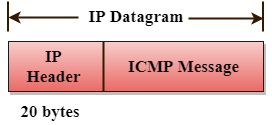
Fig 4: ICMP
Format of ICMP

Fig 5: ICMP format
● The message's form is defined in the first sector.
● The reason for a particular message form is specified in the second sector.
● The checksum field is used to verify the integrity of the entire ICMP message.
Q8) Define IP?
A8) An IP stands for internet protocol. An IP address is assigned to each device connected to a network. Each device uses an IP address for communication. It also behaves as an identifier as this address is used to identify the device on a network. It defines the technical format of the packets. Mainly, both the networks, i.e., IP and TCP, are combined together, so together, they are referred to as TCP/IP. It creates a virtual connection between the source and the destination.
We can also define an IP address as a numeric address assigned to each device on a network. An IP address is assigned to each device so that the device on a network can be identified uniquely. To facilitate the routing of packets, TCP/IP protocol uses a 32-bit logical address known as IPv4(Internet Protocol version 4).
Function:
The internet protocol's main purpose is to provide hosts with addresses, encapsulate data into packet structures, and route data from source to destination through one or more IP networks. The internet protocol provides two main items in order to achieve these functionalities, which are mentioned below.
● Format of IP packet
● IP Addressing system
IP packet
Until an IP packet is sent over the network, it contains two main components: a header and a payload.

Fig 6: IP packet
An IP header provides a lot of details about the IP packet, such as:
● The source IP address is that of the person who is sending the data.
● IP address of the destination: The destination is a host that collects data from the sender.
● Header length
● Packet length
● TTL (Time to Live) of a packet is the amount of hops that must occur before the packet is discarded.
● The internet protocol's transport protocol, which can be TCP or UDP, is known as the transport protocol.
The IP header contains a total of 14 fields, one of which is optional.
The data to be transported is known as the payload.
Q9) Define voice over IP?
A9) The idea is to use the Internet, with some added capabilities, as a telephone network. This programme allows contact between two parties over the packet-switched Internet, instead of communicating over a circuit-switched network.
Two protocols were developed to deal with this kind of Communication:
SIP(Session Initiation Protocol) and H.323
Session Initiation Protocol (SIP)
The Session Initiation Protocol (SIP) is an application layer protocol established by IETE that creates, manages and terminates a multimedia session (call). Two-party, multiparty, or multicast sessions can be generated using it.
SIP is built to be independent of the underlying transport layer; UDP, TCP, or SCTP may be used.
Message:
SIP is a protocol based on text, and so is HTTP. SIP uses messages, as does HTTP. There are six specified messages.
There is a header and a body in each post. The header consists of several lines which describe the message structure, the capacity of the caller, media type, and so on.

Fig 7: SIP message
● A session with the INVITE message is initialised by the caller.
● The caller sends an ACK message for clarification after the caller answers the call.
● A session is terminated by a BYE call.
● The OPTIONS message asks about the capabilities of a computer.
● The CANCEL message cancels an initialization process which has already begun.
● When the callee is not available, the REGISTER message allows a connection.
Address
A telephone number identifies the sender in a periodic telephone correspondence, and another telephone number identifies the recipient. SIP is very versatile. To distinguish the sender and recipient, an e-mail address, an IP address, a telephone number, and other types of addresses may be used in SIP. The address needs to be in SIP format, though (also called scheme).

Fig 8: SIP address format
Simple sessions
Three modules consist of a basic session using SIP: Establish, Communicating, and terminating.
● Establish a session: It takes a three-way handshake to create a session in SIP. Using UDP, TCP, or SCTP to start contact, the caller sends an INVITE request. She sends a response message if the caller is ready to start the session.
● Communicating: The caller and the callee will communicate by using two temporary ports after the session has been created.
● Terminating the session: With a BYE message sent by either side, the session can be terminated.
Tracking the callee
What happens if there isn't a callee sitting in her terminal? She might be away or at another terminal from her system. If DHCP is being used, she does not even have a set IP address. SIP has a function that seeks the IP address of the terminal at which the callee is sitting (similar to one in DNS). SIP uses the idea of registration to do this monitoring. Some servers are specified by SIP as registrars. A user is registered with at least one registrar server at any time; that server knows the callee's IP address.
The caller should use the e-mail address rather than the IP address in the INVITE message when a caller wants to connect with the caller. The message goes to a server that is a proxy. The proxy server sends a search message (not part of the SIP) to the server of the registrar that registered the call. The proxy server takes the caller's INVITE message and adds the newly discovered IP address of the caller when the proxy server receives a reply message from the registrar's server. This message is sent to the callee, then.
H.323
H.323 is a standard developed by lTV to allow computers (called terminals in H.323) linked to the Internet to communicate to telephones on the public telephone network.
A gateway links the telephone network to the Internet. A gateway is typically a five-layer interface that can convert a message from one stack of protocols to another. The gateway does the very same thing here. It converts a message from the telephone network into an Internet message. As we mentioned in SIP, the gatekeeper server on the local area network plays the role of the registrar server.

Fig 9: Architecture of H.323
Q10) Explain IPv6?
A10) Internet Protocol version 6 (IPv6) is the latest revision of the Internet Protocol (IP) and the first version of the protocol to be widely deployed. IPv6 was developed by the Internet Engineering Task Force (IETF) to deal with the long-anticipated problem of IPv4 address exhaustion. The Internet has grown exponentially and the address space allowed by IPv4 is saturating.
There is a requirement of protocol which can satisfy the need of future Internet addresses which are expected to grow in an unexpected manner. Using features such as NAT, has made the Internet discontinuous i.e. one part which belongs to intranet, primarily uses private IP addresses; which has to go through a number of mechanisms to reach the other part, the Internet, which is on public IP addresses.
What is IPv6?
IPv4 produces 4 billion addresses, and the developers think that these addresses are enough, but they were wrong. IPv6 is the next generation of IP addresses. The main difference between IPv4 and IPv6 is the address size of IP addresses. The IPv4 is a 32-bit address, whereas IPv6 is a 128-bit hexadecimal address. IPv6 provides a large address space, and it contains a simple header as compared to IPv4.
It provides transition strategies that convert IPv4 into IPv6, and these strategies are as follows:
● Dual stacking: It allows us to have both the versions, i.e., IPv4 and IPv6, on the same device.
● Tunneling: In this approach, all the users have IPv6 and communicate with an IPv4 network to reach IPv6.
● Network Address Translation: The translation allows the communication between the hosts having a different version of IP.
This hexadecimal address contains both numbers and alphabets. Due to the usage of both the numbers and alphabets, IPv6 is capable of producing over 340 undecillion (3.4*1038) addresses.
IPv6 is a 128-bit hexadecimal address made up of 8 sets of 16 bits each, and these 8 sets are separated by a colon. In IPv6, each hexadecimal character represents 4 bits. So, we need to convert 4 bits to a hexadecimal number at a time
The address format of IPv6:

Fig 10: Address format of IPV6
The above diagram shows the address format of IPv4 and IPv6. An IPv4 is a 32-bit decimal address. It contains 4 octets or fields separated by 'dot', and each field is 8-bit in size. The number that each field contains should be in the range of 0-255. Whereas an IPv6 is a 128-bit hexadecimal address. It contains 8 fields separated by a colon, and each field is 16-bit in size.
Q11) Write the difference between IPv6 and IPv4?
A11) Differences between IPv4 and IPv6
| Ipv4 | Ipv6 |
Address length | IPv4 is a 32-bit address. | IPv6 is a 128-bit address. |
Fields | IPv4 is a numeric address that consists of 4 fields which are separated by dot (.). | IPv6 is an alphanumeric address that consists of 8 fields, which are separated by colon. |
Classes | IPv4 has 5 different classes of IP address that includes Class A, Class B, Class C, Class D, and Class E. | IPv6 does not contain classes of IP addresses. |
Number of IP address | IPv4 has a limited number of IP addresses. | IPv6 has a large number of IP addresses. |
VLSM | It supports VLSM (Virtual Length Subnet Mask). Here, VLSM means that Ipv4 converts IP addresses into a subnet of different sizes. | It does not support VLSM. |
Address configuration | It supports manual and DHCP configuration. | It supports manual, DHCP, auto-configuration, and renumbering. |
Encryption and Authentication | It does not provide encryption and authentication. | It provides encryption and authentication. |
Address representation | In IPv4, the IP address is represented in decimal. | In IPv6, the representation of the IP address is hexadecimal. |
Packet flow identification | It does not provide any mechanism for packet flow identification. | It uses a flow label field in the header for the packet flow identification. |
Q12) What is unicast routing?
A12) The majority of internet and intranet traffic, also known as unicast data or unicast traffic, is routed to a specific destination. Unicast routing is the process of sending unicast data via the internet. Because the destination is already known, it is the simplest form of routing. As a result, all the router has to do is check the routing table and forward the packet to the next step.
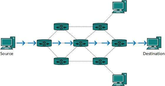
Fig 11: Unicast routing
Unicast packets can be routed using one of two routing protocols:
Distance Vector Routing Protocol
Distance Vector is a straightforward routing technique that bases its decisions on the number of hops between the source and the destination. The best route is one that has the fewest amount of hops. To other routers, each router presents its collection of optimal routes. Finally, all routers construct their network topologies based on peer router ads.
Routing Information Protocol, for example (RIP).
Link State Routing Protocol
The Link State protocol is a little more sophisticated than the Distance Vector protocol. It considers the states of all the routers in a network's links. This technique aids in the creation of a network-wide shared graph. The optimum path for routing is then calculated by all routers. Open Shortest Path First (OSPF) and Intermediate System to Intermediate System (IS-IS) are two examples (ISIS).
Q13) Explain Multicast routing protocol?
A13) Multicast routing is a subset of broadcast routing, with unique characteristics and challenges. Packets are sent to all nodes via broadcast routing, even if they do not want them. However, in Multicast routing, data is only sent to nodes that desire to receive packets.
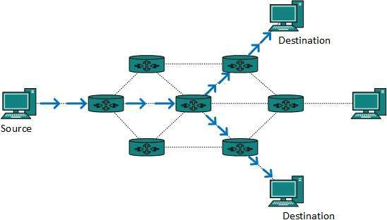
Fig 12: Multicast routing
Multicast routing methods employ trees, i.e. spanning tree, to eliminate loops, whereas Unicast routing protocols use graphs. The shortest path spanning tree is the best tree.
● DVMRP - Distance Vector Multicast Routing Protocol
● MOSPF - Multicast Open Shortest Path First
● CBT - Core Based Tree
● PIM - Protocol independent Multicast
Protocol Independent Multicast (PIM) is currently widely utilised. It comes in two different flavors:
PIM Dense Mode -
Source-based trees are used in this mode. It's employed in high-density environments like LANs.
PIM Sparse Mode -
Shared trees are used in this manner. In a sparse setting, such as a WAN, it is employed.
Q14) Describe choke packets?
A14) Both virtual networks and datagram subnets can benefit from the choke packet strategy. A choke packet is a message delivered by a node to the source informing it that the network is congested. Each router keeps track of its resources and how many of its output lines are in use. The router sends a choke packet to the source anytime resource use exceeds the threshold value defined by the administrator, giving it feedback to minimize traffic. Congestion is not reported to the intermediate nodes via which the packets passed.

In network maintenance and quality management, a choke packet is used to notify a specific node or transmitter that its broadcast traffic is causing network congestion. As a result, the node or transmitter is forced to lower its output rate.
Choke packets are used to control network congestion and flow. The router addresses the source node directly, forcing it to reduce its transmission rate. The source node responds by lowering the sending rate by a certain percentage.
A source quench packet for the Internet Control Message Protocol (ICMP) is a form of choke packet commonly used by routers.
Routers are used in a choke packet's congestion control and recovery approach. Routers often scan the network for anomalies by looking at things like line use, queuing, and buffer length. Routers transmit choke packets to all related segments in the event of congestion to reduce data throughput. Depending on variables such as the size of the congestions, available bandwidth, and buffer size, the source node congesting the network must reduce throughput by a particular factor.
Q15) What is the difference between unicast and multicast?
A15) Difference between Unicast and Multicast
S.No. | Unicast | Multicast |
1. | It has one sender and one receiver. | It has one or more senders and multiple receivers. |
2. | It sends data from one device to single device. | It sent data from one device to multiple devices. |
3. | It works on Single Node Topology. | It works on star, mesh, tree and hybrid topology. |
4. | It does not scale well for streaming media. | It does not scale well across large networks. |
5. | Multiple unicasting utilizes more bandwidth as compared. | It utilizes bandwidth efficiently. |
6. | Web surfing, file transfer is an example of a unicast. | Switch is an example of a multicast device. |
7. | It has one-to-one mapping. | It has one-to-many mapping. |