a) P=2n=2*5=10 poles Total number of slots= 5 slots/pole/phase * 10 poles * 3-phase=150 a) Ns=
|
a) Ns= b) rotor speed N=Ns(1-s) =1200(1-0.04) =1152 rpm c)when rotor speed is 500 rpm, slip s=(Ns-N)/Ns= (1200-500)/1200=0.58 rotor current frequency f’=sf=0.58x50=29.17 Hz
|
Ns=
R2=2ohm, X2=4ohm Z2=R2+jX2=2+j4=4.47
slip at speed 1200rpm s= Rotor impedance at slip s=0.4 is Z2s=R2+jsX2=2+jx0.4x4=2.56
|
Standstill emf/rotor phase=70/ Rotor impedance/phase= Rotor current/phase=40.4/5.09=7.92A Power factor cosφ=0.99
|
Rotor resistance/phase=2+1=3 ohm Rotor impedance/phase= Rotor current/phase= (70/ Cosφ=3/5.83=0.514
|
|
From above equation slip is directly proportional to rotor resistance. Hence speed decreases. This method is applicable to wound rotor induction motor.
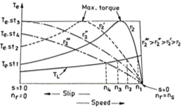
Fig 1 (b): Torque speed characteristics
|
At the normal operating condition, the slip increases with increasing torque so there is curve is linear. For a fixed load curve, the speed is downward from n1 to n4. From this figure we can also obtain the maximum torque at the starting of the resistance r2”. So, this method has an advantage of achieving maximum torque at the starting period.But the maximum torque is independent of the rotor resistance as per the equation,
|
|
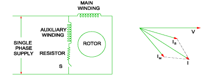
A10) In this type of motor an auxiliary winding is connected in addition to the main winding. There is one switch called centrifugal switch (S) which disconnects the auxiliary winding from the main winding. If the starting winding has high resistance than only a phase difference can be created between these windings. The main purpose of creating this phase difference is to get the magnetic field rotated because IM cannot self-start.
|


