Unit - 5
Single Phase Machines
Q1) Explain the working of single phase induction motor.
A1)
A single-phase induction motor consists of a single-phase winding mounted on the stator and a cage winding on the rotor. When a single-phase supply is connected to the stator winding a pulsating magnetic field is produced. Under these conditions, the rotor does not rotate due to inertia. Therefore, the single-phase induction motor is inherently not self-starting and requires some special starting means.
If, however, the single-phase stator winding is excited and the rotor of the motor is started by an auxiliary means, and the starting device is then removed, the motor continues to rotate in the direction in which it is started.
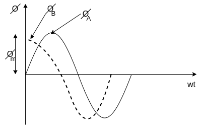
Consider two windings a,b so displaced that they produce magnetic fields 90° apart in space.
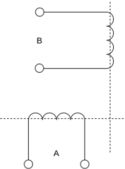
Suppose that these windings produce magnetic fields equal in magnitude and 90° apart in the time given by


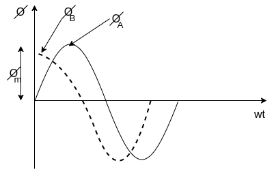
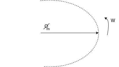
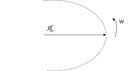
The resultant of these fields is the rotating magnetic field of constant magnitude  . This rotating magnetic field may be represented by a phasor constant magnitude
  .
.
Q2) Explain Double revolving field theory of single-phase induction motors.
A2)
Double revolving field theory of single-phase induction motors.
The double-revolving field theory of single-phase induction motors states that a stationary pulsating magnetic field can be resolved into two rotating magnetic fields, each of equal magnitude but rotating in opposite directions. The induction motor response to each magnetic field separately and the net torque in the motor is equal to the sum of the torques due to each of the two magnetic fields.
The equation for an alternating magnetic field whose axis is fixed in space is given by

Where  is the maximum value of the sinusoidally distributed air-gap flux density produced by a properly distributed stator winding carrying an alternating current of frequency
  is space displacement angle measured from the axis of the stator winding.


The first term on the RHS represents the equation of a revolving field moving in the positive  direction. It has a maximum value equal to
The second term on the RHS represents the equation of revolving field moving in negative  direction. It has a maximum value equal to
The field moving in the positive  direction is called the forward rotating field. The field moving in the negative
  direction is called a backward rotating field.
The positive direction is the direction in which the single-phase motor is started initially.
When the rotor is stationary, the induced voltages are equal and opposite consequently two torques are also equal and opposite. Hence, at standstill, the net torque is zero. In other words, a single-phase induction motor with a single stator winding inherently has no starting torque.
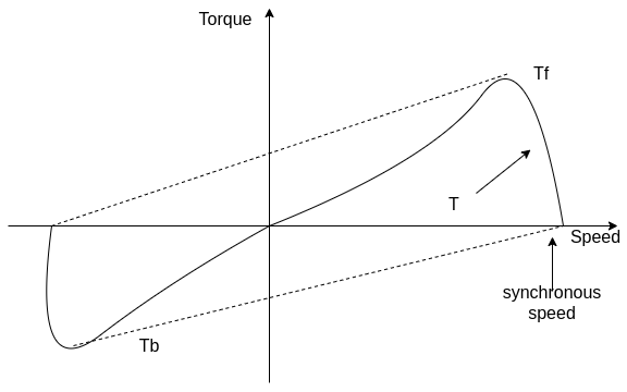
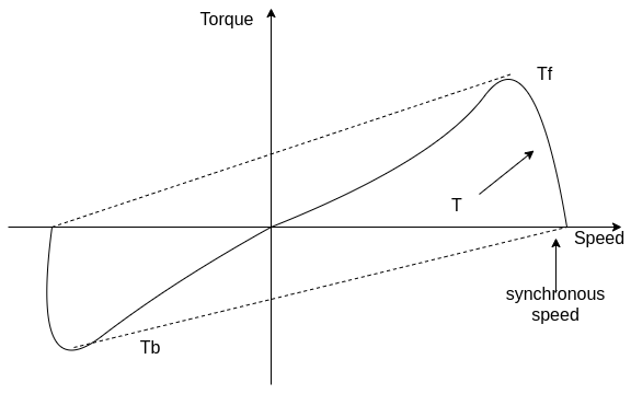
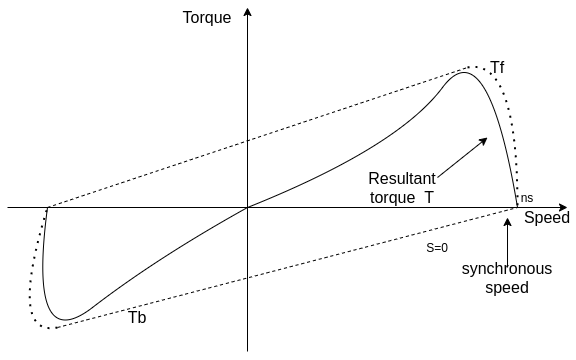
Q3) Explain with torque-speed characteristic rotor slip with respect to two rotating fields.
A3)
Rotor slip with respect to two rotating fields
If the rotor is started by auxiliary means, it will develop torque and continue to run in the same direction as one of the fields. By definition, the direction in which the router is started initially will be called the forward field.
Let  = synchronous speed, n=rotor speed
The slip of the rotor with respect to the forward rotating field is

Since the backward rotating flux rotates opposite to the stator, the sign of n must be changed to obtain the backward slip.
Thus, the slip of the rotor with respect to the backward rotating field is


Adding 1 and 2


The first equation corresponds to a motor operation and the second equation denotes the braking region. Thus, the two torques have an opposite influence on the rotor.
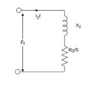
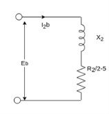
The router equivalent circuits for the forward and backward rotating fluxes are shown below.
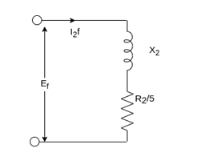
For forwarding rotating flux wave
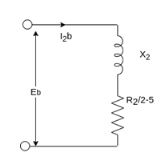
At stands still, the impedances are equal and therefore, the current  are equal. These currents produce mmfs which oppose the stator mmfs equally. Therefore, the rotating forward and backward flux is in the air gap are equal in magnitude and no torque is developed.
However, when the rotor rotates the impedance of the rotor circuits are unequal and the rotor current  is greater than the rotor current
Since the value of S is generally small (around 0.05)  is considerable higher than
  . Therefore,
  is greater than
  and forward flux is greater than the backward flux.
However resultant flux remains essentially constant. This resultant flux induces a voltage in the stator winding. Both flux waves induce voltages in the rotor and produce torque in the rotor. These two torques are in opposite directions. The net induced torque in the motor is equal to the difference between these torques.
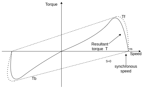
Q4) Draw and explain the equivalent circuit of single phase induction motor.
A4)
Equivalent circuit of Single Phase Induction Motor-
Most single-phase induction motors are two-phase motors in which the auxiliary winding is disconnected from the supply when the machine reaches a certain value. The machine then operates, as a true single-phase motor running on its main winding.
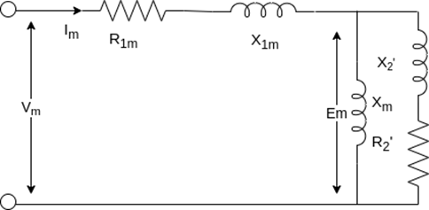
Consider the rotor is stationary and only the main winding is excited. The motor behaves like a single-phase transformer with its secondary short-circuited.
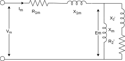
Where,
 = resistance of the main winding
 = leakage reactance of the main stator winding.
 = magnetizing reactance
 = stand Steel rotor resistance referred to the main stator winding.
 = standstill rotor leakage reactance refers to the main stator winding.
 = applied voltage
 = main winding current
The core loss branch is not shown, the core losses will be assumed to be lumped with the mechanical and stray losses as a part of the rotational losses of the motor.
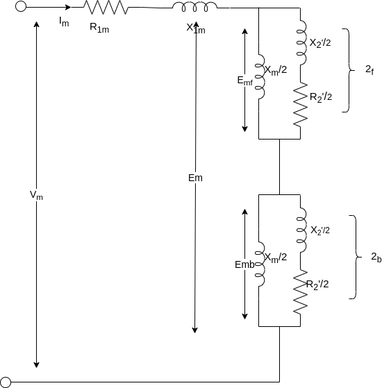
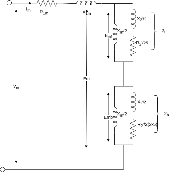
According to the double-revolving field theory, the pulsating air gap flux in the motor at standstill can be resolved into two equal and opposite fluxes with the motor.
Thus, a single-phase induction motor may be considered as consisting of two motors having a common stator winding and two imaginary rotors, which rotate in opposite directions.
The standstill impedance of each rotor refers to the main stator is 
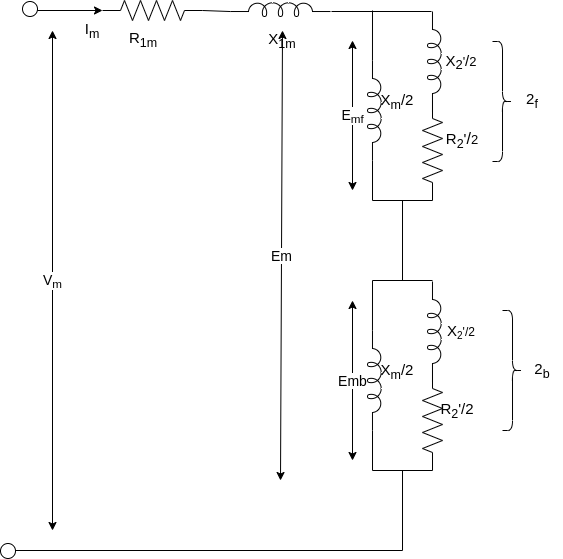
At standstill with the effects of forward & backward rotating fluxes. The first portion shows the effect of forwarding rotating flux, and the second portion shows the effect of backward rotating flux.

At standstill, 
Now suppose that the motor is started with the help of an auxiliary winding and the auxiliary winding is switched out after the motor gains its normal speed.
S=the slip of the rotor with respect to the forward rotating flux.
(2-S)=the slip of the rotor with respect to the backward rotating flux.
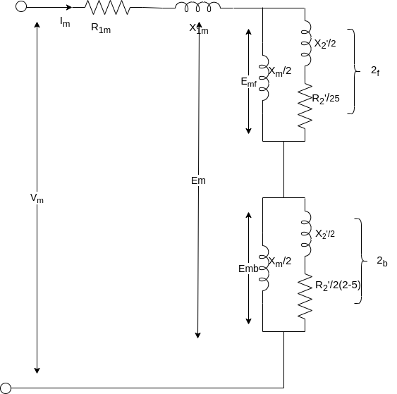
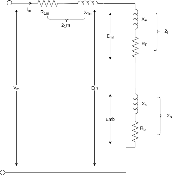
For simplification


Here  =rotor impedance offered to the forward field.
 =rotor impedance offered to the backward field.


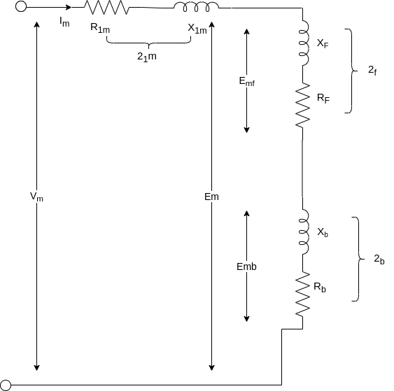
The current in stator winding is

Q5) A 230volt 50 HZ, 4 pole single-phase induction motor has the following equivalent circuit impedances.

Friction windage and core loss =40W
For a slip of 0.03 pu, calculate
a) Input current
b) Power factor
c) Developed power
d) Output power
e) Efficiency
A5)


For the forward field circuit


For the backward field circuit


a) Input current 

b) Power factor=Cos(-60.95°)=0.4856 lagging
c) Developed power 

=479.65W
d) Output power=
=479.65-40=439.65 watt
Input power= 
=230×5.685×0.4856
=6349W
e) Efficiency=


Q6) A 230 volt 50 HZ, 4 pole single-phase induction motor has the following equivalent circuit parameters  Friction and windage, core losses are 50 Watt and slip is 0.025. Calculate
a) input current
b) power factor
c) developed power
d) output power
e) efficiency
A6)


For the forward field


For the backward field


a) Input current=

b) Power factor=cos(-66.0865)
=0.4053 lagging
c) Developed power 

=347.49 watt
d) Output power= 


Input power=VI


e) Efficiency= 

=56.17%
Q7) A 2 pole, 50 HZ, 230-volt universal motor has 1200 armature turns and 400 series field turns. When operated on AC, the full load current is 1 A, field flux is 0.0008 weber and speed is 7000 rpm. The total resistance and leakage reactance are 20 ohm and 30 ohm respectively. Find
a) Transformer EMF induced in the armature winding by the quadrature flux
b) Quadrature flux
c) HP output
d) Speed of operation if machine is connected to DC supply and takes 1 A. The armature is wave wound.
A7)
a) 
A=2, Z=1200*2, 


=158.37V

= √2 π (50) (400)(0.0008)
=71V
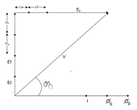
The phasor diagram is shown below
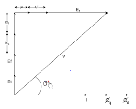


Et = 44.2 V
b) 
44.2 = 2 × √2 (50) 

c) 

=0.814
Cos θ = 0.776 lagging
Power input= V I Cos θ
= 230 × 1 × 0.776
= 178.48 watt
Copper losses = l2(ra+rf)
= 20 watt
Neglecting other losses=power output=178.48-20
=158.48 watt

When connected to DC supply
Vdc = 230 Vr Idc = 1 A
Ebdc = 230 – Idc (ra + rf)
=230-20
=210V


=9282 rpm
Q8) The motor of above example is provided with a compensating winding having a resistance of 2 ohm and reactance of 5 ohm. The compensating winding neutralizes armature flux completely. Find the speeds of operation on AC and DC if V=230V and I=1A
A8)
Since ϕq has been neutralized fully
Et = 0,Xc = 5Ω,rc = 2Ω
V2 = 
2302 = (71 + 1(30 + 5))2 + [ Er + 1 (20 + 2)]2
Er = 182.12 V
If Nac is the new speed for AC operation

Nac = 8050 rpm
When connected to DC supply
Erdc = Vdc – Idc (ra + rf + rc)
=230 – 1(20 +2 )
=208

Ndc = 9194 rpm
Q9) A universal series motor has a resistance of 30 and an inductance of 0.5 H. When connected to a 250 V dc supply and loaded to take 0.8 A it runs at 2000 rpm. Determine the speed, torque and power factor, when connected to a 250 V, 50 Hz ac supply and loaded to take the same current.
A9)
Operation of motor on dc
Ebdc = V-IaRa = 250-0.8 x 30 = 226V
Ndc = 2000rpm
Operation motor on ac
XL = 2πfL = 2πx 50x0.5=157 𝛀
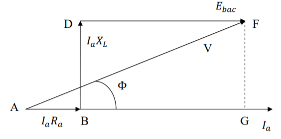
From phasor below we get
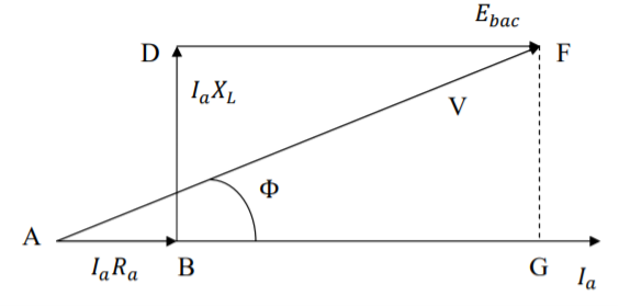
AF2 = AG2 + GF2
V2 = (AB + BG)2 + GF2 = (AB + DF)2 + GF2
= (Ia Ra + Ebac)2 + (IaXl)2
Ebac = - 0.8 × 30 + 
= - 24 + 216.12 = 192.12 V
Since the currents in dc and ac operation are equal, the flux will also be equal ɸac= ɸdc


Power factor cos ϕ =  (lagging)
Mechanical power developed
Pmech = Ebac Ia = 192.12 × 0.8 = 153.7 W
Torque developed
τ = 
Q10) Compare single phase induction motor and three phase induction motor.
A10)
Single phase induction motors are constructed in fractional kilowatt capacity and are used in places where three phase supply is not readily available.
Sr. No | Single phase induction motor | Three phase induction motor |
1 | Single phase induction motor develops about 50% of the output of that of three phase Motors for the same size and temperature rise. | Output of three phase induction motor is more compare two single phase induction motor for the same size and temperature rise |
2 | Single phase induction motor have lower power factor | Better power factor |
3 | The starting torque is low in single phase induction motor | Starting torque is high, Also maximum torque can be obtained at starting condition |
4 | Single phase Motors are costly than 3 phase Motors of the same rating | Less costly |
5 | They are generally available up to 1 kW rating. | They are available up to 50000 kW |
Q11) A three-phase, 12 pole, salient pole alternator is coupled to a diesel engine running at 500rpm. It supplies an induction motor which has a full load speed of 1440 rpm. Find the percentage slip and number of poles of the induction motor.
A11)
Frequency of supply to the induction motor f = pn/120 = 12 x 500 / 120 = 50 Hz
Speed of Induction motor = 1440 rpm
Number of poles of induction motor = p = 120 f / n = 120 x 50/1440 = 4.16
The number of poles are to be even
Selecting the nearest even number as thenumber of poles p = 4
Synchronous speed of the induction motor
Ns = 120f/p = 120 x 50 /4 = 1500 rpm
Slip = (Ns – N) / Ns = (1500 – 1440)/ 1500 = 0.04
Percentage slip = 4 %
Q12) A three phase, 50 Hz, 4 pole slip ring induction motor has a star connected rotor. The full load speed of the motor is 1460 rpm. The rotor resistance and stand still reactance
Per phase are 0.1 ohm and 1.5 ohm respectively. The open circuit voltage on open circuit between the slip rings is 90 volts. Determine (i) percentage slip (ii) induced emf in rotor per phase (iii) the rotor reactance per phase at full load (iv) the rotor current and full load power factor
A12)
(i) Ns = 120f/p = 120 x 50 /4 = 1500 rpm
Slip = (Ns – N) / Ns = (1500 – 1460)/ 1500 = 0.0266Percentage slip = 2.66 %
(ii) Induced emf per phase in rotor at stand still = 90/√3 =51.96 volts
Rotor induced emf at full load Er = sE2
= 0.0266 x 51.96 = 1.382 volts
(iii) rotor reactance at stand still = 1.5 Ω / phase
Rotor reactance per phase at full load = sX2
= 0.0399 Ω / phase
(iv) rotor impedance per phase at full load = Z2
= √(R22+ sX22) = 0.1077 Ω
Rotor current per phase = 1.382/0.1077 = 12.83 amps
Full load power factor = R2/Z2
= 0.1/ 0.1077 = 0.929
Q13) If the induced emf in the stator of an 8-pole induction motor has a frequency of 50 Hz and that in the rotor is 1.5 Hz, at what speed is the motor running and what is the slip?
A13)
f = 50 Hz and fr = 1.5 Hz, Ns = 120f/p = 120 x 50/8 = 750 rpm
We have fr = sf
Hence s= fr /f = 1.5/50 = 0.03
Hence N = (1- s)Ns = (1- 0.03) x 750 = 727.5 rpm
Q14) The power input to a rotor of 440V, 50Hz, 6-pole, 3-phase, induction motor is 60kW. The rotor force is observed to make 80 alterations per minute. Calculate i) slip ii) rotor speed iii) rotor cu loss per phase?
A14)
80 alterations per minute=80/60 cycles per second=1.333Hz=sf
i)slip=1.333/50=0.027 P.u.=2.7%
Ii)Rotor speed N=(1-s) Ns=(1-0.027) x 1000=973.33rpm
Ns=120f/P=120 x 50/6=1000rpm
Iii)rotor cu loss/phase= =
= =0.54Kw
Q15) The power input to a 3-phase induction motor is 80kW. The stator loss is total 1kW. Find the mechanical power developed and the rotor cu loss per phase if the slip is 3%?
A15)
P2= stator input – stator losses=80-1=79kW
Pm=(1-s)P2==(1-0.03) x 79=76.63kW
Total rotor cu loss=sP2=0.03 x 79=2.37kW
Rotor cu loss per phase=2.37x1000/3=790W
Q16) The power input to a rotor of a 400V, 50hz,6-pole, 3-phaseinduction motor is 15kW. The slip is 4%. Calculate i) frequency of rotor current. i)rotor speed. Iii)rotor cu loss iv) rotor resistance/phase if rotor current is 50A?
A16)
i) frequency of rotor current=sf=0.04 x 50=2Hz
Ii) Rotor speed N=(1-s) Ns=(1-0.04) x 1000=960rpm
Ns=120f/P=120 x 50/6=1000rpm
Iii) rotor cu loss=s x rotor input=0.04 x 15=0.6kW
Iv)rotor cu loss/phase=0.6 x 1000/3=200W
602R2=200
R2=0.055Ω
Q17) A 110V, 3-phase star connected induction motor takes 25A at a line voltage of 30V with rotor locked. With this line voltage power input to motor is 400W and core loss is 30 W. The dc resistance between the pair of stator terminals is 0.1 ohm. If ratio of ac to dc resistance is 1.6. Find equivalent leakage reactance per phase and stator and rotor resistance per phase?
A17)
S.C voltage/phase= 30/ =17.3V
Is=25A/phase
Z01=17.3/25=0.7ohm/phase
Stator and cu loss=400-30=370W
3 x 252xR01=370
R01=0.197ohm
Leakage reactance/phase X01= =
= =0.67ohm
Dc resistance/phase stator=0.1/2=0.05ohm
Ac resistance/phase R1=0.05x1.6=0.08ohm
Effective resistance/phase rotor referred to stator  =0.197-0.08=0.117ohm
Q18) In a no load test an induction motor took 8A and 440W with a line voltage of 110V. If the stator resistance/phase is 0.05ohm and frictional and windage losses are 135W. Calculate the exciting conductance and susceptance/phase?
A18)
Stator cu loss=3 R1=3x82x0.05=9.6W
Stator core loss=440-135-9.6=295.4W
Voltage/phase v=110/ V
V
Core loss=3G0V2
295.4=3 G0(110/ )2
)2
G0=0.024siemens/phase
Y0=I0/V=(8// /110=0.042siemens/phase
B0= =0.034siemens/phase
Q19) Explain construction and working of hysteresis motor?
A19)
A Hysteresis Motor is a synchronous motor with a uniform air gap and without DC excitation. It operates both in single and three phase supply.
The Torque in a Hysteresis Motor is produced due to hysteresis and eddy current induced in the rotor by the action of the rotating flux of the stator windings.
The working of the motor depends on the working of the continuously revolving magnetic flux. For the split phase operation, the stator winding of the motor has two single phase supply. This stator winding remains continuously connected to the single phase supply both at the starting as well as the running of the motor.
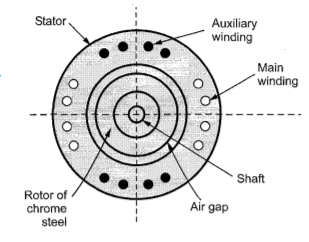
The rotor of the motor is made up of smooth chrome steel cylinder and it has no winding. It has high retentivity and because of this, it is very difficult to change the magnetic polarities once they are caused by the revolving flux of the rotor. The rotor of the hysteresis motor moves synchronously because the pole of the motor magnetically locks with the stator which has opposite polarities.
Construction of Stator of Hysteresis Motor
The stator of the hysteresis motor produces a rotating magnetic field and is almost similar to the stator of the induction motor. Thus, the stator of the motor is connected either to single supply or to the three phase supply.
The stator winding of the single-phase hysteresis motor is made of permanent split capacitor type or shaded pole type. The capacitor is used with an auxiliary winding in order to produce a uniform field.
Construction of Rotor of Hysteresis Motor
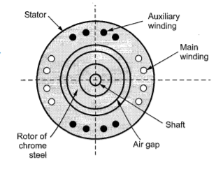
The rotor of the hysteresis motor consists of the core of aluminium or some other non-magnetic material which carries a layer of special magnetic material. The figure shows the rotor of the hysteresis motor.
The outer layer has a number of thin rings forming a laminated rotor. The rotor of the motor is a smooth cylinder, and it does not carry any windings. The ring is made of hard chrome or cobalt steel having a large hysteresis loop as shown in the figure below.
Operation of a Hysteresis Motor
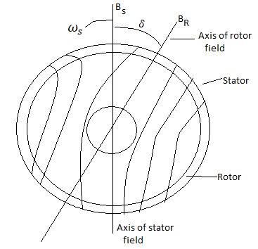
When supply is given applied to the stator, a rotating magnetic field is produced. This magnetic field magnetises the rotor ring and induces pole within it.
Due to the hysteresis loss in the rotor, the induced rotor flux lags behind the rotating stator flux.
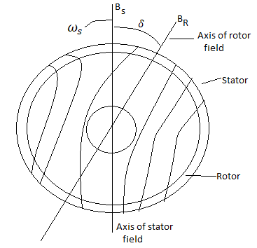
The angle δ between the stator magnetic field BS and the rotor magnetic field BR is responsible for the production of the torque. The angle δ depends on the shape of the hysteresis loop and not on the frequency.
Thus, the value of Coercive force and residual flux density of the magnetic material should be large.
The ideal material would have a rectangular hysteresis loop as shown by loop 1 in the hysteresis loop figure. The stator magnetic field produces Eddy currents in the rotor. As a result, they produce their own magnetic field.
The eddy current loss is given by the equation,
Pe = Kef2 s2 B2
Where, ke is Eddy current constant
f2 is the eddy current frequency
B is the flux density
The relation between rotor frequency f2 and supply frequency f1 is f2 = sf1 where s is the slip.
Therefore, Pe = Ke s2 f12 B2
The torque due to eddy current is Te = Pe/sws or Te = K’s
K’= Kef12B2/ws
The hysteresis loss is Ph = Khf2B1.6 or Kh sf1B1.6
The Torque due to hysteresis is Th = Ph/sws= k’’
K’’ = Khf1B1.6/ws
From the equation it is clear that the torque is proportional to the slip. Therefore, as the speed of the rotor increases the value of Ʈe decreases.
As the speed of the motor reaches synchronous speed, the slip becomes zero and torque also becomes zero.
As the electromagnet torque is developed by the motor is because of the hysteresis loss and remains constant at all rotor speed until the breakdown torque.
At the synchronous speed, the eddy current torque is zero and only torque due to hysteresis loss is present.
Torque Speed characteristic of Hysteresis Motor
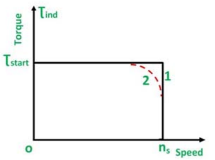
The speed torque curve of the motor is shown below.
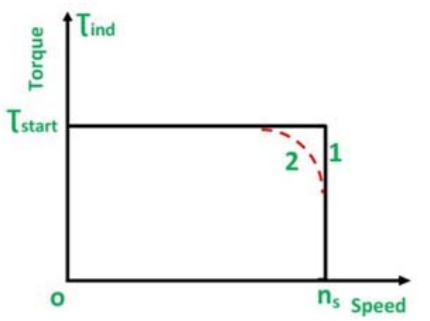
Curve 1 is the ideal curve, and the curve 2 is the practical hysteresis motor curve.
The torque-speed characteristic of the hysteresis motor is different from an induction motor.
Since, at the synchronous speed, the torque developed by an induction motor becomes zero, whereas in the hysteresis motor the torque is constant at all the speed even at the synchronous speed.
Thus, from the curve, it is seen that the locked rotor, starting and pull out torque is equal.
The noise level of the hysteresis motor is very low as compared to the induction motor because it operates at a constant speed and its rotor is smooth.
This type of motor is smoothest running, quietest single phase motor and is used for quality sound reproduction equipment like record players, tape recorders, etc. It is also employed in electric clocks and other timing devices.
Q20) Explain construction and working of BLDC motors?
A20)
The term “DC motor” is traditionally used to refer to “brushed DC motors”. In DC motors section, we have seen that brushes are required to convert alternating current generated in DC generators to direct current (and vice versa for DC motors). We have also seen that a “field winding” is used to produce the magnetic field required for energy conversion. If the winding is replaced by permanent magnets, the rotating magnetic field is then generated without the need of separate winding. Besides, the losses in the field will be eliminated. There has been a significant improvement in permanent magnet technology since last few years. The permanent magnets are alloys like Neodymium Iron Boron (NdFeB) and Samarium Cobalt have become popular in recent years. Now, if permanent magnets are placed on rotor, the armature winding will be stationary and hence brushes can be removed. This has two advantages - 1. Resistive losses in brushes are completely eliminated 2. Maintenance and safety issues are also taken care of. Thus, the DC motor with permanent magnets without brushes is called brushless DC motor or simply BLDC motor.
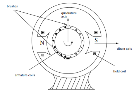
The operating principle of BLDC motor is same as that of the DC motor. Conductors facing a particular magnet pole (say N pole) carry current in one direction while those facing the other pole carry current in opposite direction. By virtue of this, the fields created by magnet and armature conductors are always orthogonal to each other as shown in the Figure. Note the naming convention “direct axis” and “quadrature axis”. N S direct axis quadrature axis armature coils field coil
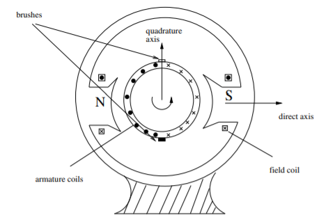
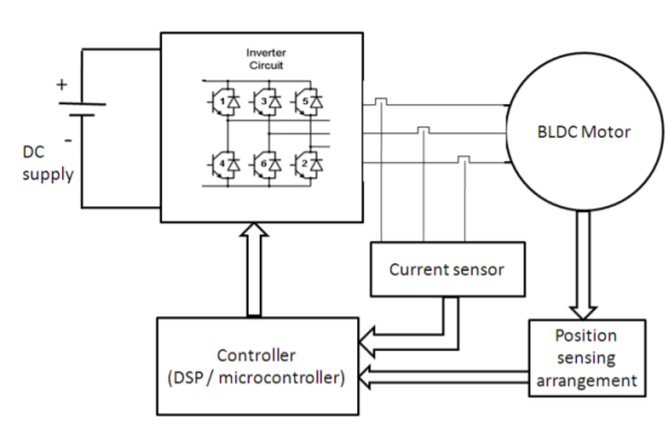
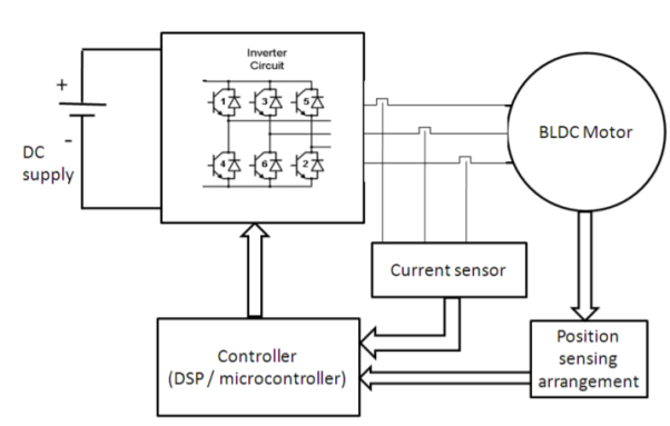
Suppose a two pole rotor is rotating under an armature. When N pole passes completely across a conductor, some mechanism is necessary to change the direction of current in that conductor. Otherwise, direction of force on the conductor will be reversed. In a conventional DC motor, the number of commutator segments equals the number of conductors in the armature. When a commutator segment. Switches from one brush to the other, there is a change in supply direction (in case of motor). In BLDC machine, this reversal of direction of current is done via power electronic switches. Now, the instant of reversing the direction is a function of position of rotor. Hence, sensing of position is required which is “fedback” to the power electronics drive which “drives and controls” the supply given to the motor. Hence complete block diagram of a BLDC drive is as shown in Figure. It consists of 3 parts
- BLDC machine
- Power electronics (DC-AC converter)
- Position sensing and drive control system
Unit - 5
Single Phase Machines
Q1) Explain the working of single phase induction motor.
A1)
A single-phase induction motor consists of a single-phase winding mounted on the stator and a cage winding on the rotor. When a single-phase supply is connected to the stator winding a pulsating magnetic field is produced. Under these conditions, the rotor does not rotate due to inertia. Therefore, the single-phase induction motor is inherently not self-starting and requires some special starting means.
If, however, the single-phase stator winding is excited and the rotor of the motor is started by an auxiliary means, and the starting device is then removed, the motor continues to rotate in the direction in which it is started.
Consider two windings a,b so displaced that they produce magnetic fields 90° apart in space.
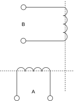
Suppose that these windings produce magnetic fields equal in magnitude and 90° apart in the time given by


The resultant of these fields is the rotating magnetic field of constant magnitude  . This rotating magnetic field may be represented by a phasor constant magnitude
  .
.
Q2) Explain Double revolving field theory of single-phase induction motors.
A2)
Double revolving field theory of single-phase induction motors.
The double-revolving field theory of single-phase induction motors states that a stationary pulsating magnetic field can be resolved into two rotating magnetic fields, each of equal magnitude but rotating in opposite directions. The induction motor response to each magnetic field separately and the net torque in the motor is equal to the sum of the torques due to each of the two magnetic fields.
The equation for an alternating magnetic field whose axis is fixed in space is given by

Where  is the maximum value of the sinusoidally distributed air-gap flux density produced by a properly distributed stator winding carrying an alternating current of frequency
  is space displacement angle measured from the axis of the stator winding.


The first term on the RHS represents the equation of a revolving field moving in the positive  direction. It has a maximum value equal to
The second term on the RHS represents the equation of revolving field moving in negative  direction. It has a maximum value equal to
The field moving in the positive  direction is called the forward rotating field. The field moving in the negative
  direction is called a backward rotating field.
The positive direction is the direction in which the single-phase motor is started initially.
When the rotor is stationary, the induced voltages are equal and opposite consequently two torques are also equal and opposite. Hence, at standstill, the net torque is zero. In other words, a single-phase induction motor with a single stator winding inherently has no starting torque.
Q3) Explain with torque-speed characteristic rotor slip with respect to two rotating fields.
A3)
Rotor slip with respect to two rotating fields
If the rotor is started by auxiliary means, it will develop torque and continue to run in the same direction as one of the fields. By definition, the direction in which the router is started initially will be called the forward field.
Let  = synchronous speed, n=rotor speed
The slip of the rotor with respect to the forward rotating field is

Since the backward rotating flux rotates opposite to the stator, the sign of n must be changed to obtain the backward slip.
Thus, the slip of the rotor with respect to the backward rotating field is


Adding 1 and 2


The first equation corresponds to a motor operation and the second equation denotes the braking region. Thus, the two torques have an opposite influence on the rotor.
The router equivalent circuits for the forward and backward rotating fluxes are shown below.
For forwarding rotating flux wave
At stands still, the impedances are equal and therefore, the current  are equal. These currents produce mmfs which oppose the stator mmfs equally. Therefore, the rotating forward and backward flux is in the air gap are equal in magnitude and no torque is developed.
However, when the rotor rotates the impedance of the rotor circuits are unequal and the rotor current  is greater than the rotor current
Since the value of S is generally small (around 0.05)  is considerable higher than
  . Therefore,
  is greater than
  and forward flux is greater than the backward flux.
However resultant flux remains essentially constant. This resultant flux induces a voltage in the stator winding. Both flux waves induce voltages in the rotor and produce torque in the rotor. These two torques are in opposite directions. The net induced torque in the motor is equal to the difference between these torques.
Q4) Draw and explain the equivalent circuit of single phase induction motor.
A4)
Equivalent circuit of Single Phase Induction Motor-
Most single-phase induction motors are two-phase motors in which the auxiliary winding is disconnected from the supply when the machine reaches a certain value. The machine then operates, as a true single-phase motor running on its main winding.
Consider the rotor is stationary and only the main winding is excited. The motor behaves like a single-phase transformer with its secondary short-circuited.
Where,
 = resistance of the main winding
 = leakage reactance of the main stator winding.
 = magnetizing reactance
 = stand Steel rotor resistance referred to the main stator winding.
 = standstill rotor leakage reactance refers to the main stator winding.
 = applied voltage
 = main winding current
The core loss branch is not shown, the core losses will be assumed to be lumped with the mechanical and stray losses as a part of the rotational losses of the motor.
According to the double-revolving field theory, the pulsating air gap flux in the motor at standstill can be resolved into two equal and opposite fluxes with the motor.
Thus, a single-phase induction motor may be considered as consisting of two motors having a common stator winding and two imaginary rotors, which rotate in opposite directions.
The standstill impedance of each rotor refers to the main stator is 
At standstill with the effects of forward & backward rotating fluxes. The first portion shows the effect of forwarding rotating flux, and the second portion shows the effect of backward rotating flux.

At standstill, 
Now suppose that the motor is started with the help of an auxiliary winding and the auxiliary winding is switched out after the motor gains its normal speed.
S=the slip of the rotor with respect to the forward rotating flux.
(2-S)=the slip of the rotor with respect to the backward rotating flux.
For simplification


Here  =rotor impedance offered to the forward field.
 =rotor impedance offered to the backward field.


The current in stator winding is

Q5) A 230volt 50 HZ, 4 pole single-phase induction motor has the following equivalent circuit impedances.

Friction windage and core loss =40W
For a slip of 0.03 pu, calculate
a) Input current
b) Power factor
c) Developed power
d) Output power
e) Efficiency
A5)


For the forward field circuit


For the backward field circuit


a) Input current 

b) Power factor=Cos(-60.95°)=0.4856 lagging
c) Developed power 

=479.65W
d) Output power=
=479.65-40=439.65 watt
Input power= 
=230×5.685×0.4856
=6349W
e) Efficiency=


Q6) A 230 volt 50 HZ, 4 pole single-phase induction motor has the following equivalent circuit parameters  Friction and windage, core losses are 50 Watt and slip is 0.025. Calculate
a) input current
b) power factor
c) developed power
d) output power
e) efficiency
A6)


For the forward field


For the backward field


a) Input current=

b) Power factor=cos(-66.0865)
=0.4053 lagging
c) Developed power 

=347.49 watt
d) Output power= 


Input power=VI


e) Efficiency= 

=56.17%
Q7) A 2 pole, 50 HZ, 230-volt universal motor has 1200 armature turns and 400 series field turns. When operated on AC, the full load current is 1 A, field flux is 0.0008 weber and speed is 7000 rpm. The total resistance and leakage reactance are 20 ohm and 30 ohm respectively. Find
a) Transformer EMF induced in the armature winding by the quadrature flux
b) Quadrature flux
c) HP output
d) Speed of operation if machine is connected to DC supply and takes 1 A. The armature is wave wound.
A7)
a) 
A=2, Z=1200*2, 


=158.37V

= √2 π (50) (400)(0.0008)
=71V
The phasor diagram is shown below


Et = 44.2 V
b) 
44.2 = 2 × √2 (50) 

c) 

=0.814
Cos θ = 0.776 lagging
Power input= V I Cos θ
= 230 × 1 × 0.776
= 178.48 watt
Copper losses = l2(ra+rf)
= 20 watt
Neglecting other losses=power output=178.48-20
=158.48 watt

When connected to DC supply
Vdc = 230 Vr Idc = 1 A
Ebdc = 230 – Idc (ra + rf)
=230-20
=210V


=9282 rpm
Q8) The motor of above example is provided with a compensating winding having a resistance of 2 ohm and reactance of 5 ohm. The compensating winding neutralizes armature flux completely. Find the speeds of operation on AC and DC if V=230V and I=1A
A8)
Since ϕq has been neutralized fully
Et = 0,Xc = 5Ω,rc = 2Ω
V2 = 
2302 = (71 + 1(30 + 5))2 + [ Er + 1 (20 + 2)]2
Er = 182.12 V
If Nac is the new speed for AC operation

Nac = 8050 rpm
When connected to DC supply
Erdc = Vdc – Idc (ra + rf + rc)
=230 – 1(20 +2 )
=208

Ndc = 9194 rpm
Q9) A universal series motor has a resistance of 30 and an inductance of 0.5 H. When connected to a 250 V dc supply and loaded to take 0.8 A it runs at 2000 rpm. Determine the speed, torque and power factor, when connected to a 250 V, 50 Hz ac supply and loaded to take the same current.
A9)
Operation of motor on dc
Ebdc = V-IaRa = 250-0.8 x 30 = 226V
Ndc = 2000rpm
Operation motor on ac
XL = 2πfL = 2πx 50x0.5=157 𝛀
From phasor below we get
AF2 = AG2 + GF2
V2 = (AB + BG)2 + GF2 = (AB + DF)2 + GF2
= (Ia Ra + Ebac)2 + (IaXl)2
Ebac = - 0.8 × 30 + 
= - 24 + 216.12 = 192.12 V
Since the currents in dc and ac operation are equal, the flux will also be equal ɸac= ɸdc


Power factor cos ϕ =  (lagging)
Mechanical power developed
Pmech = Ebac Ia = 192.12 × 0.8 = 153.7 W
Torque developed
τ = 
Q10) Compare single phase induction motor and three phase induction motor.
A10)
Single phase induction motors are constructed in fractional kilowatt capacity and are used in places where three phase supply is not readily available.
Sr. No | Single phase induction motor | Three phase induction motor |
1 | Single phase induction motor develops about 50% of the output of that of three phase Motors for the same size and temperature rise. | Output of three phase induction motor is more compare two single phase induction motor for the same size and temperature rise |
2 | Single phase induction motor have lower power factor | Better power factor |
3 | The starting torque is low in single phase induction motor | Starting torque is high, Also maximum torque can be obtained at starting condition |
4 | Single phase Motors are costly than 3 phase Motors of the same rating | Less costly |
5 | They are generally available up to 1 kW rating. | They are available up to 50000 kW |
Q11) A three-phase, 12 pole, salient pole alternator is coupled to a diesel engine running at 500rpm. It supplies an induction motor which has a full load speed of 1440 rpm. Find the percentage slip and number of poles of the induction motor.
A11)
Frequency of supply to the induction motor f = pn/120 = 12 x 500 / 120 = 50 Hz
Speed of Induction motor = 1440 rpm
Number of poles of induction motor = p = 120 f / n = 120 x 50/1440 = 4.16
The number of poles are to be even
Selecting the nearest even number as thenumber of poles p = 4
Synchronous speed of the induction motor
Ns = 120f/p = 120 x 50 /4 = 1500 rpm
Slip = (Ns – N) / Ns = (1500 – 1440)/ 1500 = 0.04
Percentage slip = 4 %
Q12) A three phase, 50 Hz, 4 pole slip ring induction motor has a star connected rotor. The full load speed of the motor is 1460 rpm. The rotor resistance and stand still reactance
Per phase are 0.1 ohm and 1.5 ohm respectively. The open circuit voltage on open circuit between the slip rings is 90 volts. Determine (i) percentage slip (ii) induced emf in rotor per phase (iii) the rotor reactance per phase at full load (iv) the rotor current and full load power factor
A12)
(i) Ns = 120f/p = 120 x 50 /4 = 1500 rpm
Slip = (Ns – N) / Ns = (1500 – 1460)/ 1500 = 0.0266Percentage slip = 2.66 %
(ii) Induced emf per phase in rotor at stand still = 90/√3 =51.96 volts
Rotor induced emf at full load Er = sE2
= 0.0266 x 51.96 = 1.382 volts
(iii) rotor reactance at stand still = 1.5 Ω / phase
Rotor reactance per phase at full load = sX2
= 0.0399 Ω / phase
(iv) rotor impedance per phase at full load = Z2
= √(R22+ sX22) = 0.1077 Ω
Rotor current per phase = 1.382/0.1077 = 12.83 amps
Full load power factor = R2/Z2
= 0.1/ 0.1077 = 0.929
Q13) If the induced emf in the stator of an 8-pole induction motor has a frequency of 50 Hz and that in the rotor is 1.5 Hz, at what speed is the motor running and what is the slip?
A13)
f = 50 Hz and fr = 1.5 Hz, Ns = 120f/p = 120 x 50/8 = 750 rpm
We have fr = sf
Hence s= fr /f = 1.5/50 = 0.03
Hence N = (1- s)Ns = (1- 0.03) x 750 = 727.5 rpm
Q14) The power input to a rotor of 440V, 50Hz, 6-pole, 3-phase, induction motor is 60kW. The rotor force is observed to make 80 alterations per minute. Calculate i) slip ii) rotor speed iii) rotor cu loss per phase?
A14)
80 alterations per minute=80/60 cycles per second=1.333Hz=sf
i)slip=1.333/50=0.027 P.u.=2.7%
Ii)Rotor speed N=(1-s) Ns=(1-0.027) x 1000=973.33rpm
Ns=120f/P=120 x 50/6=1000rpm
Iii)rotor cu loss/phase= =
= =0.54Kw
Q15) The power input to a 3-phase induction motor is 80kW. The stator loss is total 1kW. Find the mechanical power developed and the rotor cu loss per phase if the slip is 3%?
A15)
P2= stator input – stator losses=80-1=79kW
Pm=(1-s)P2==(1-0.03) x 79=76.63kW
Total rotor cu loss=sP2=0.03 x 79=2.37kW
Rotor cu loss per phase=2.37x1000/3=790W
Q16) The power input to a rotor of a 400V, 50hz,6-pole, 3-phaseinduction motor is 15kW. The slip is 4%. Calculate i) frequency of rotor current. i)rotor speed. Iii)rotor cu loss iv) rotor resistance/phase if rotor current is 50A?
A16)
i) frequency of rotor current=sf=0.04 x 50=2Hz
Ii) Rotor speed N=(1-s) Ns=(1-0.04) x 1000=960rpm
Ns=120f/P=120 x 50/6=1000rpm
Iii) rotor cu loss=s x rotor input=0.04 x 15=0.6kW
Iv)rotor cu loss/phase=0.6 x 1000/3=200W
602R2=200
R2=0.055Ω
Q17) A 110V, 3-phase star connected induction motor takes 25A at a line voltage of 30V with rotor locked. With this line voltage power input to motor is 400W and core loss is 30 W. The dc resistance between the pair of stator terminals is 0.1 ohm. If ratio of ac to dc resistance is 1.6. Find equivalent leakage reactance per phase and stator and rotor resistance per phase?
A17)
S.C voltage/phase= 30/ =17.3V
Is=25A/phase
Z01=17.3/25=0.7ohm/phase
Stator and cu loss=400-30=370W
3 x 252xR01=370
R01=0.197ohm
Leakage reactance/phase X01= =
= =0.67ohm
Dc resistance/phase stator=0.1/2=0.05ohm
Ac resistance/phase R1=0.05x1.6=0.08ohm
Effective resistance/phase rotor referred to stator  =0.197-0.08=0.117ohm
Q18) In a no load test an induction motor took 8A and 440W with a line voltage of 110V. If the stator resistance/phase is 0.05ohm and frictional and windage losses are 135W. Calculate the exciting conductance and susceptance/phase?
A18)
Stator cu loss=3 R1=3x82x0.05=9.6W
Stator core loss=440-135-9.6=295.4W
Voltage/phase v=110/ V
V
Core loss=3G0V2
295.4=3 G0(110/ )2
)2
G0=0.024siemens/phase
Y0=I0/V=(8// /110=0.042siemens/phase
B0= =0.034siemens/phase
Q19) Explain construction and working of hysteresis motor?
A19)
A Hysteresis Motor is a synchronous motor with a uniform air gap and without DC excitation. It operates both in single and three phase supply.
The Torque in a Hysteresis Motor is produced due to hysteresis and eddy current induced in the rotor by the action of the rotating flux of the stator windings.
The working of the motor depends on the working of the continuously revolving magnetic flux. For the split phase operation, the stator winding of the motor has two single phase supply. This stator winding remains continuously connected to the single phase supply both at the starting as well as the running of the motor.
The rotor of the motor is made up of smooth chrome steel cylinder and it has no winding. It has high retentivity and because of this, it is very difficult to change the magnetic polarities once they are caused by the revolving flux of the rotor. The rotor of the hysteresis motor moves synchronously because the pole of the motor magnetically locks with the stator which has opposite polarities.
Construction of Stator of Hysteresis Motor
The stator of the hysteresis motor produces a rotating magnetic field and is almost similar to the stator of the induction motor. Thus, the stator of the motor is connected either to single supply or to the three phase supply.
The stator winding of the single-phase hysteresis motor is made of permanent split capacitor type or shaded pole type. The capacitor is used with an auxiliary winding in order to produce a uniform field.
Construction of Rotor of Hysteresis Motor
The rotor of the hysteresis motor consists of the core of aluminium or some other non-magnetic material which carries a layer of special magnetic material. The figure shows the rotor of the hysteresis motor.
The outer layer has a number of thin rings forming a laminated rotor. The rotor of the motor is a smooth cylinder, and it does not carry any windings. The ring is made of hard chrome or cobalt steel having a large hysteresis loop as shown in the figure below.
Operation of a Hysteresis Motor
When supply is given applied to the stator, a rotating magnetic field is produced. This magnetic field magnetises the rotor ring and induces pole within it.
Due to the hysteresis loss in the rotor, the induced rotor flux lags behind the rotating stator flux.
The angle δ between the stator magnetic field BS and the rotor magnetic field BR is responsible for the production of the torque. The angle δ depends on the shape of the hysteresis loop and not on the frequency.
Thus, the value of Coercive force and residual flux density of the magnetic material should be large.
The ideal material would have a rectangular hysteresis loop as shown by loop 1 in the hysteresis loop figure. The stator magnetic field produces Eddy currents in the rotor. As a result, they produce their own magnetic field.
The eddy current loss is given by the equation,
Pe = Kef2 s2 B2
Where, ke is Eddy current constant
f2 is the eddy current frequency
B is the flux density
The relation between rotor frequency f2 and supply frequency f1 is f2 = sf1 where s is the slip.
Therefore, Pe = Ke s2 f12 B2
The torque due to eddy current is Te = Pe/sws or Te = K’s
K’= Kef12B2/ws
The hysteresis loss is Ph = Khf2B1.6 or Kh sf1B1.6
The Torque due to hysteresis is Th = Ph/sws= k’’
K’’ = Khf1B1.6/ws
From the equation it is clear that the torque is proportional to the slip. Therefore, as the speed of the rotor increases the value of Ʈe decreases.
As the speed of the motor reaches synchronous speed, the slip becomes zero and torque also becomes zero.
As the electromagnet torque is developed by the motor is because of the hysteresis loss and remains constant at all rotor speed until the breakdown torque.
At the synchronous speed, the eddy current torque is zero and only torque due to hysteresis loss is present.
Torque Speed characteristic of Hysteresis Motor
The speed torque curve of the motor is shown below.
Curve 1 is the ideal curve, and the curve 2 is the practical hysteresis motor curve.
The torque-speed characteristic of the hysteresis motor is different from an induction motor.
Since, at the synchronous speed, the torque developed by an induction motor becomes zero, whereas in the hysteresis motor the torque is constant at all the speed even at the synchronous speed.
Thus, from the curve, it is seen that the locked rotor, starting and pull out torque is equal.
The noise level of the hysteresis motor is very low as compared to the induction motor because it operates at a constant speed and its rotor is smooth.
This type of motor is smoothest running, quietest single phase motor and is used for quality sound reproduction equipment like record players, tape recorders, etc. It is also employed in electric clocks and other timing devices.
Q20) Explain construction and working of BLDC motors?
A20)
The term “DC motor” is traditionally used to refer to “brushed DC motors”. In DC motors section, we have seen that brushes are required to convert alternating current generated in DC generators to direct current (and vice versa for DC motors). We have also seen that a “field winding” is used to produce the magnetic field required for energy conversion. If the winding is replaced by permanent magnets, the rotating magnetic field is then generated without the need of separate winding. Besides, the losses in the field will be eliminated. There has been a significant improvement in permanent magnet technology since last few years. The permanent magnets are alloys like Neodymium Iron Boron (NdFeB) and Samarium Cobalt have become popular in recent years. Now, if permanent magnets are placed on rotor, the armature winding will be stationary and hence brushes can be removed. This has two advantages - 1. Resistive losses in brushes are completely eliminated 2. Maintenance and safety issues are also taken care of. Thus, the DC motor with permanent magnets without brushes is called brushless DC motor or simply BLDC motor.
The operating principle of BLDC motor is same as that of the DC motor. Conductors facing a particular magnet pole (say N pole) carry current in one direction while those facing the other pole carry current in opposite direction. By virtue of this, the fields created by magnet and armature conductors are always orthogonal to each other as shown in the Figure. Note the naming convention “direct axis” and “quadrature axis”. N S direct axis quadrature axis armature coils field coil
Suppose a two pole rotor is rotating under an armature. When N pole passes completely across a conductor, some mechanism is necessary to change the direction of current in that conductor. Otherwise, direction of force on the conductor will be reversed. In a conventional DC motor, the number of commutator segments equals the number of conductors in the armature. When a commutator segment. Switches from one brush to the other, there is a change in supply direction (in case of motor). In BLDC machine, this reversal of direction of current is done via power electronic switches. Now, the instant of reversing the direction is a function of position of rotor. Hence, sensing of position is required which is “fedback” to the power electronics drive which “drives and controls” the supply given to the motor. Hence complete block diagram of a BLDC drive is as shown in Figure. It consists of 3 parts
- BLDC machine
- Power electronics (DC-AC converter)
- Position sensing and drive control system
