Unit - 3
Potential of charge system, Conductors, Dielectric, Capacitance and Poison’s and Laplace Equations
Q1) A parallel plate capacitor with plate separation 3.54mm and area 2m is initially charged to a potential difference of 1000 volts. The charging batteries are then disconnected. A dielectric sheet with the same thickness as that of the separation between the plates and having a dielectric constant of 2 is then inserted between the capacitor plates. Determine (a) the capacitance, (b) potential difference across the capacitor plates, (c) surface charge density (d) the electric field and (e) displacement vector, before and after the insertion of the dielectric.
A1) (a) The capacitance before insertion of the dielectric is

After the insertion the capacitance doubles and becomes 10-8F
(b) Potential difference between the plates before insertion is given to be 1000 V. On introducing the dielectric it becomes half, i.e. 500 V.
(c) The charge on each capacitor plate was Q=CV = 5 x10⁻⁶ C giving a surface charge density of 2.5 x 10⁻⁶ C/m. The free charge density remains the same on introduction of the dielectric.
(d) The electric field strength E is given by

The electric field strength is reduced to 1.4 x 10⁵ volt/meter on insertion.
(e) The displacement vector remains the same in both cases as the free charge density is not altered. It is given by

Q2) The parallel plates of a capacitor of plate dimensions axb and separation d are charged to a potential difference and battery is disconnected. A dielectric slab of relative permittivity k is inserted between the plates of the parallel plate capacitor such that the left hand edge of the slab is at a distance x from the left most edge of the capacitor. Calculate (a) the capacitance and (b) the force on the dielectric.
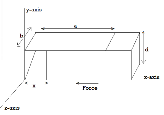
A2) Since the battery is disconnected, the potential difference between the plates will change while the charge remains the same. Since the capacitance of the part of the capacitor occupied by the dielectric is increased by a factor k, the effective capacitance is due to two capacitances in parallel,

The energy stored in the capacitor is

Let F be the force we need to apply in the x-direction to keep the dielectric in place. For an infinitisimal increment dx of x, we have to do an amount of work Fdx of work, which will increase the energy stored in the field by dU , so that

The differentiation is to be done, keeping the charge Q constant. Thus

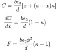
Since, k>1, F is positive. This means the electric field pulls the dielectric inward so that an external agency has to apply an outward force to keep the dielectric in position. Since the initial potential difference is given by Q/C, one can express the force in terms of this potential

This is the force that the external agency has to apply to keep the left edge of the dielectric at x. The force with which the capacitor pulls the dielectric in has the same magnitude.
Q3) In the above example, what would be the force if the battery remained connected?
A3) If the battery remained connected Q does not remain the same, the potential does. The battery must do work to keep the potential constant. It may be realised that the force exerted on the dielectric in a particular position depends on the charge distribution (of both free and bound charges) existing in that position and the force is independent of whether the battery stays connected or is disconnected. However, in order to calculate the force with battery remaining connected, one must, explicitly take into account the work done by the battery in computing the total energy of the system. The total energy U now has two parts, one the work done by the external agency Fdx and the other the work done by the battery, viz., ɸ dQ where dQ is the extra charge supplied by the battery to keep the potential constant. Thus
U= Fdx+ ɸdQ


Q4) The space between the plates of a parallel plate capacitor is filled with two different dielectrics, as shown. Find the effective capacitance.
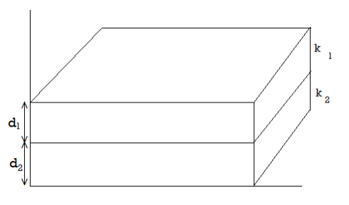
A4) Take a Gaussian pill-box as shown. We have

As there are no free charges inside the dielectric. Contribution to the integral comes only from the faces of the pill-box parallel to the plates and Hence,

Where  is the surface density of free charges
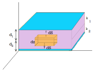
Let ɸ1 be the potential difference between the upper plate and the interface between the dielectric and ɸ2 that between the interface and the lower plate. We have
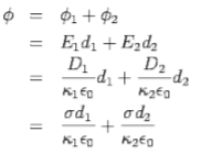
Thus, the effective capacitance is given by
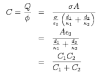
Q5) A capacitor consists of an inner conducting sphere of radius R and an outer conducting shell of radius 2R. The space between the spheres is filled with two different linear dielectrics, one with a dielectric constant from r=R to r=1.5R and the other with dielectric constant 2k from r=1.5R to r=2R. The outer shell has a charge -Q while the inner conductor has a charge +Q. Determine the electric field for r>0 and find the effective capacitance
A5) The electric field is radially symmetric and may be obtained by applying Gauss's law for the displacement vector
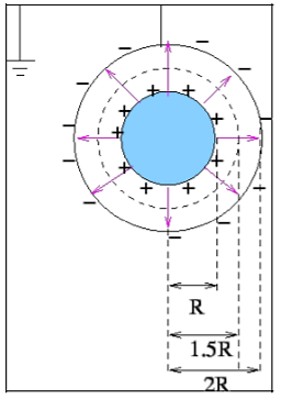
For r<R, the field is zero as the free charges are only on the surface of the inner cylinder.

For


The fields are radial with the inner sphere at a higher potential. The potential difference is calculated by taking the taking the line integral of the electric field along any radial line.
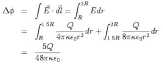
The effective capacitance is

Q6) A parallel plate capacitor has charge densities  on its plates which are separated by a distance d. The space between the capacitor plates is filled with a linear but inhomogeneous dielectric. The dielectric constant varies with distance from the positive plate linearly from a value 1 to a value 2 at the negative plate. Determine the effective capacitance.
A6) As the dielectric is linear,

As the insertion of dielectric does not affect free charges, the displacement vector  remains the same as it would in the absence of the dielectric. Thus

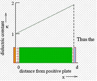
Thus the electric field  is given by

The field close to x=d is given by

Which shows that adjacent to the negative plate there is a positive charge density. To find the effective capacitance, we find the potential difference between the plates by integrating the electric field
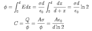
The polarization is given by

The volume density of bound charges, given by


Q7) List the difference between potential difference and electromotive force?
A7)
Potential Difference | Electromotive Force [EMF] |
Work done by electric force (Fe) on unit positive charge to move it through a distance l in the direction of electric field id called potential difference | EMF is defined as the work done by the force to move unit positive charge from negative to positive terminal of battery. |
P.D = v=w/q=Fel/q | EMF= W/q= Fed/q |
S.I unit is volts | Si Unit is volts |
Potential difference is effect | EMF is a cause |
It depends upon resistance of circuit | It does not depend upon the resistance |
It is always less than emf | It is greater than potential difference |
It does not remain constant | It remains constant |
Potential difference takes place between two points | EMF creates potential difference in entire circuit. |
Q8) List the various distribution of charges in application of potential field?
A8) We have seen so far the charge distributions have been discrete i.e. made up of individual point particles.
If a charge distribution is continuous rather than discrete, we can generalize the definition of the electric field. We simply divide the charge into infinitesimal pieces and treat each piece as a point charge.
We know that charge is quantized so there is no such thing as a truly continuous charge distribution. However, in most practical cases, the total charge creating the field involves such a huge number of discrete charges.
For simplicity we can safely ignore the discrete nature of the charge and consider it to be continuous. This is exactly the kind of approximation we make when we deal with a bucket of water as a continuous fluid rather than a collection of H2O molecules.
Continuous charge distribution: an arrangement of many discrete charges so closely spaced that the charge is treated as a continuum, resulting in a replacement of discrete sums with integrals.
Distribution of charges
(a) Line charge density
(b) Surface charge density
(c) Volume charge density
(d) Some of the components of the total electric field cancel out, with the remainder resulting in a net electric field
Definitions of charge density:
(a) λ - Line charge: charge per unit length (linear charge density); units are coulombs per meter (C/m)
(b)  - Surface charge density: Charge per unit area; units are coulombs per square meter (C/m2)
(c)  - Volume charge density: Charge per unit volume; units are coulombs per cubic meter (C/m3)
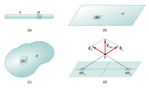
Figure: Charge Distribution
Some of the important result for electric field due to point charge, line charge density, surface charge density and volume charge density.
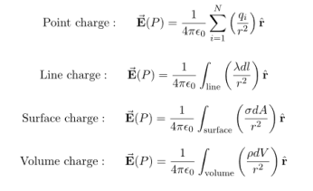
Note carefully the meaning of r in these equations: It is the distance from the charge element λdl,  ,
,  to the location of interest, P(x,y,z) (the point in space where you want to determine the field). However, don’t confuse this with the meaning of
  .
.
If the charge distribution is continuous, the potential at a point P can be found by summing over the contributions from individual differential elements of charge. Dq
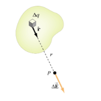
Figure: Continuous charge distribution
Consider the charge distribution shown in Figure. Taking infinity as our reference point with zero potential, the electric potential at P due to dq is

Summing over contributions from all differential elements, we have

We established the relation between  and V. If we consider two points which are separated by a small distance
  , the following differential form is obtained.
DV = -
In Cartesian coordinates,
E = Ex  + Ey
+ Ey + Ez
+ Ez
And  = dx
= dx  + dy
+ dy + dz
+ dz
DV = ( Ex  + Ey
+ Ey + Ez
+ Ez ) .( dx
  + dy
+ dy + dz
+ dz )
)
DV = ( Ex dx+ Eydy + Ezdz
This implies
Ex =  Ey =
Ey =  Ez =
Ez = 
By introducing a differential quantity called the “del (gradient) operator”

The electric field can be written as

 =-
=- 
Notice that ∇ operates on a scalar quantity (electric potential) and results in a vector quantity (electric field). Mathematically, we can think of  as the negative of the gradient of the electric potential V. Physically, the negative sign implies that if V increases as a positive charge moves along some direction, say x, with , then there is a non-vanishing component of
  in the opposite direction(-Ex
  )
)
In the case of gravity, if the gravitational potential increases when a mass is lifted a distance h, the gravitational force must be downward.
If the charge distribution possesses spherical symmetry, then the resulting electric field is a function of the radial distance r, i.e.  = Er
= Er 
In this case, .dV=- Er dr.
If V(r) is known, then  may be obtained as

For example, the electric potential due to a point charge q is
V = 

Using the above formula, the electric field is simply
E = 

Q9) Explain basic laws of electrostatics?
A9) LAWS IN ELECTROSTATICS
There are some important laws we used in electrostatics.
Coulomb’s Law:
The magnitude of the electric force that a particle exerts on another particle is directly proportional to the product of their charges and inversely proportional to the square of the distance between them. The direction of the force is along the line joining the particles.
Mathematically, the electric force F that a particle of charge q’ exerts on a particle of charge q at a distance r is given by the formula
F =k

Where k is a constant of proportionality. This formula not only gives the magnitude of the force, but also the direction, if we interpret a positive value of the force F as repulsive and a negative value as attractive.
When a small positive test charge is brought near a large positive charge, it experiences a force directed away from the large charge. If the test charge is far from the large charge, the electrostatic force given by Coulomb's law is smaller than when it is near. This data of direction and magnitude of an electrostatic force, due to a fixed charge or set of fixed charges, constitutes an electrostatic field. The electric field is defined as the force per unit charge exerted on a small positive test charge (q 0) placed at that point. Mathematically,
E = 
Note that both the force and electric field are vector quantities.
Figure: is a pictorial representation of the electric fields surrounding a positive charge and a negative charge. These lines are called field lines or lines of force.
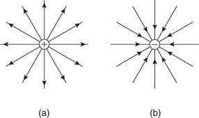
Figure: Electric field lines of (a) positive and (b) negative point charges.
Figure shows the electric fields for opposite charges, similar charges, and oppositely charged plates.
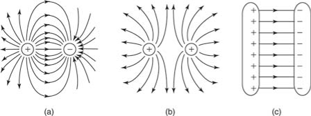
Figure: Electric field lines of (a) two opposite charges, (b) two like charges, and (c) two oppositely charged plates.
Electric flux
Electric flux is defined as the number of field lines that pass through a given surface. In Figure , lines of electric flux emerging from a point charge pass through an imaginary spherical surface with the charge at its center.
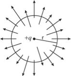
Figure: Electric flux
Gauss’s law of electrostatics
It states that the electric flux through any closed surface is proportional to the total electric charge enclosed by this surface.
Φ=q/ϵ0
Gauss’s law for magnetism
Gauss’s law for magnetism states that no magnetic monopoles exists and that the total flux through a closed surface must be zero.
Net flux = ∫ B • dA = 0
Faraday’s law
Faraday’s law states that a current will be induced in a conductor which is exposed to a changing magnetic field
Q10) Derive expression of electric field due to dipole?
A10) Case (i) Electric field due to an electric dipole at points on the axial line
Consider an electric dipole placed on the x-axis as shown in Figure 6. A point C is located at a distance of r from the midpoint O of the dipole along the axial line.
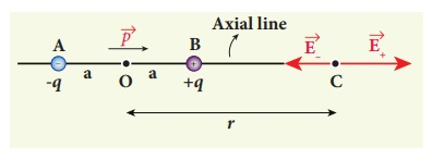
Figure: Electric field of the dipole on the axial line
The electric field at a point C due to +q is
 ………(1)
Since the electric dipole moment vector  is from –q to +q and is directed along BC, the above equation is rewritten as
 ………(2)
Where p ^ is the electric dipole moment unit vector from –q to +q.
The electric field at a point C due to –q is
 ………(3)
Since +q is located closer to the point C than –q,  , is stronger than
  , Therefore, the length of the
  vector is drawn larger than that of
  vector.
The total electric field at point C is calculated using the superposition principle of the electric field.
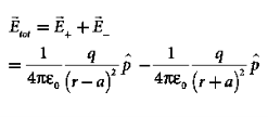 ………(4)
 ………(5)
 ………(6)
Note that the total electric field is along  , since +q is closer to C than –q.
The direction of  , is shown in Figure.
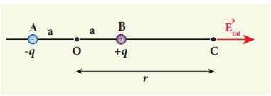
Figure: Total electric field of the dipole on the axial line
If the point C is very far away from the dipole then (r >> a). Under this limit the term ( r2 − a2 )2 ≈ r4 . Substituting this into equation (6), we get
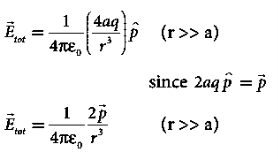 ………(7)
If the point C is chosen on the left side of the dipole, the total electric field is still in the direction of  .
.
Case (ii) Electric field due to an electric dipole at a point on the equatorial plane
Consider a point C at a distance r from the midpoint O of the dipole on the equatorial plane as shown in Figure 8 .
Since the point C is equidistant from +q and –q, the magnitude of the electric fields of +q and –q are the same. The direction of  is along BC and the direction of
  is along CA.
  and
and  are resolved into two components; one component parallel to the dipole axis and the other perpendicular to it. The perpendicular components |
 | sinθ and |
 | sinθ are oppositely directed and cancel each other. The magnitude of the total electric field at point C is the sum of the parallel components of
  + and
+ and  and its direction is along -
 as shown in the Figure 8.
 ………(8)
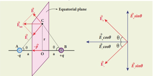
Figure: Electric field of the dipole at a point on the equatorial plane
The magnitudes  + and
+ and  are the same and are given by
 ………(9)
By substituting equation (9) into equation (8), we get
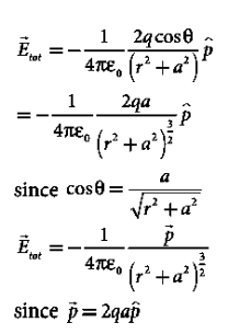 ………(10)
At very large distances (r>>a), the equation (10) becomes
 ………(11)
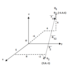
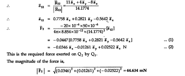
Q11) A charge Q1=-20µC is located at P(-6,4,6) and a charge Q2=50µC is located at R(5,8,-2) in a free space . Find the force exerted on Q2 by Q1 in vector form. The distances given are in meters.
A11)
From the co-ordinates of P and R the respective position vectors are:

And


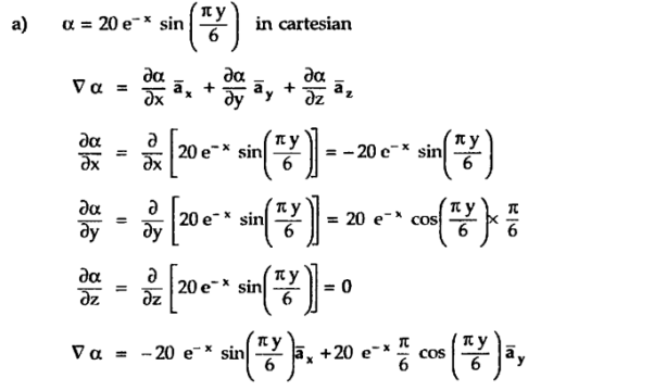
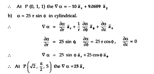
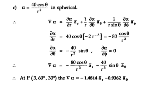
Q12) A scalar field is given by


A12)
Q13) What are dielectric materials? Classify them?
A13)
A dielectric is an electrical insulator that can be polarized by an applied electric field. Or
A dielectric is non-conducting material which stores electrical charges.
In other words, A material that does not conduct electricity but on applying electric field, induced charges produced on its faces. Such an insulator is called Dielectric.
Dielectrics are insulators i.e. non-conducting substances which are bad conductor of electric current. Dielectric materials can stores an electrostatic charge while dissipating minimal energy in the form of heat.
Examples of dielectric are Mica, Plastics, Glass, Porcelain and Various Metal Oxides and even dry air is also example of dielectric. The dielectric constant of a vacuum is, of course, unity.
Classification of Dielectric
The response of a dielectric material depends on the nature of its molecules. The molecules of a dielectric is of two types
- Polar molecules
- Non polar molecules
Polar Molecules: Polar Molecules are those in which centre of gravity of positive and negative charge does not coincide with each other. This is because they all are asymmetric in shape. Examples: H2O, CO2, NO2 etc. The molecule of material are composed of two or more different atoms, which have permanently dipole moment because the centre of gravity of positive charge and negative charge does not coincide with each other but separated by a finite (small) distance.
Normally this type of molecular dipole in polar dielectric are randomly oriented such that their net dipole moment becomes zero and material act as a neutral material.
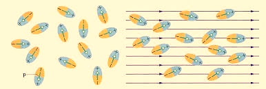
Figure: Effect of electric felid on dielectric
Polar Molecules are those type of dielectric in which the possibilities that the positive and negative molecules will coincide with each other is null or zero.
Non-Polar Molecule: Non-polar molecules are those in which centre of gravity of positive charge and negative charge coincide with each other. The molecule has zero dipole moment as they all are symmetric in shape. Examples: O2, N2, H2 etc.
Dielectrics materials in which the molecule's center of gravity of positive charge and negative charge coincide with each other and so the molecules are electrically neutral and hence zero dipole moment.
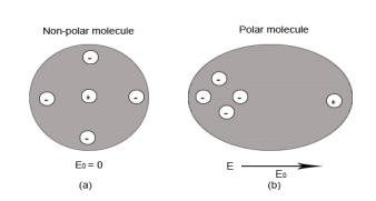
Figure Polar molecules & Non polar molecules
Difference between Dielectric and Insulators
Dielectrics are often confused with insulators. Here are some points of differences
- Dielectric is the material which stores the electrical energy in an electric field whereas insulator is that material which blocks the flow of electrons.
- Dielectric material is polarised whereas insulator material doesn’t get polarised.
- Molecules in dielectric are weakly bounded as compared to molecules in insulator.
- Dielectric material has high dielectric constant whereas insulator has low dielectric constant.
- Examples of Dielectric material are dry air, vacuum, Glass, Porcelain, Various Metal Oxides and distilled water. Whereas Examples of insulator are cotton, plastic, rubber etc.
In dielectric material molecules are tightly bounded to the nucleus and not able to move freely as in case of conductor. But when a dielectric material is placed in an electric field, electric charges do not flow through the material as they flow in case of an electrical conductor but only slightly shift from their average equilibrium positions causing dielectric polarization. Because of dielectric polarization, positive charges are displaced in the direction of the field and negative charges shift in the direction opposite to the field. In dielectric molecules are tightly bound to the nucleus and not able to move freely as in case of conductors. The dielectric material is largely used in the manufacturing of capacitor.
Response of Dielectric to External Electric Field
In case of Polar Molecules -When the electric field is not present, it causes the electric dipole moment of these molecules in a random direction. This is why the average dipole moment is zero. If the external electric field is present, the molecules align themselves in the direction electric field and resulted in having dipole moment.
In case of Non-Polar Molecules – As we know nonpolar molecule has zero dipole moment. In spite of zero dipole, when a dielectric nonpolar material is placed in an electric field. The positive and the negative charges in a nonpolar molecule experience forces in opposite directions. This force causes the separation between the charges and hence nonpolar molecule experiences induced dipole moment.
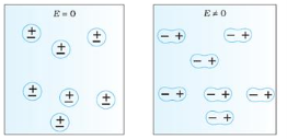
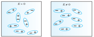
Figure (a) (left) Non Polar Molecule (b) (right) Polar Molecule
Q14) Derive expression for electric field and electrostatic potential for a continuous charge distribution
A14)
If the charge distribution is continuous, the potential at a point P can be found by summing over the contributions from individual differential elements of charge. Dq
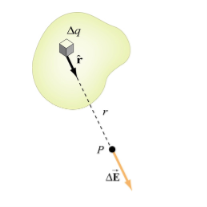
Figure: Continuous charge distribution
Consider the charge distribution shown in Figure. Taking infinity as our reference point with zero potential, the electric potential at P due to dq is

Summing over contributions from all differential elements, we have

We established the relation between  and V. If we consider two points which are separated by a small distance
  , the following differential form is obtained.
DV = -
In Cartesian coordinates,
E = Ex  + Ey
+ Ey + Ez
+ Ez
And  = dx
= dx  + dy
+ dy + dz
+ dz
DV = ( Ex  + Ey
+ Ey + Ez
+ Ez ) .( dx
  + dy
+ dy + dz
+ dz )
)
DV = ( Ex dx+ Eydy + Ezdz
This implies
Ex =  Ey =
Ey =  Ez =
Ez = 
By introducing a differential quantity called the “del (gradient) operator”

The electric field can be written as

 =-
=- 
Notice that ∇ operates on a scalar quantity (electric potential) and results in a vector quantity (electric field). Mathematically, we can think of  as the negative of the gradient of the electric potential V. Physically, the negative sign implies that if V increases as a positive charge moves along some direction, say x, with , then there is a non-vanishing component of
  in the opposite direction(-Ex
  )
)
In the case of gravity, if the gravitational potential increases when a mass is lifted a distance h, the gravitational force must be downward.
If the charge distribution possesses spherical symmetry, then the resulting electric field is a function of the radial distance r, i.e.  = Er
= Er 
In this case, .dV=- Er dr.
If V(r) is known, then  may be obtained as

For example, the electric potential due to a point charge q is
V = 

Using the above formula, the electric field is simply
E = 

Q15) Write down Laplace’s and Poisson’s equations for electrostatic potential?
A15)
A useful approach to the calculation of electric potentials is to relate that potential to the charge density which gives rise to it. The electric field is related to the charge density by the divergence relationship
 =
= 
E = Electric field
 = Charge density
 = Permittivity
And the electric field is related to the electric potential by a gradient relationship
E = 
Therefore the potential is related to the charge density by Poisson's equation
 =
=  2V =
2V = 
In a charge-free region of space, this becomes Laplace's equation
 2V = 0
This mathematical operation, the divergence of the gradient of a function, is called the Laplacian. Expressing the Laplacian in different coordinate systems to take advantage of the symmetry of a charge distribution helps in the solution for the electric potential V.
For example, if the charge distribution has spherical symmetry, you use the Laplacian in spherical polar coordinates.
Since the potential is a scalar function, this approach has advantages over trying to calculate the electric field directly. Once the potential has been calculated, the electric field can be computed by taking the gradient of the potential.
Q16) Write a note on divergence of electrostatic field? What is its Physical Interpretation?
A16)
The electric field can be graphically represented using field lines. The direction of the field lines indicates the direction in which a positive test charge moves when placed in this field. The density of field lines per unit area is proportional to the strength of the electric field. Field lines originate on positive charges and terminate on negative charges. Field lines can never cross since if this would occur, the direction of the electric field at that particular point would be undefined. Examples of field lines produced by positive point charges are shown in Figure
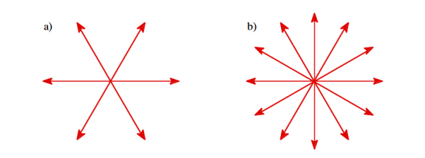
Figure: a) Electric field lines generated by a positive point charge with charge q. b) Electric field lines generated by a positive point charge with charge 2q.
The flux of electric field lines through any surface is proportional to the number of field lines passing through that surface. Consider for example a point charge q located at the origin. The electric flux  E through a sphere of radius r, centered on the origin, is equal to
 E = surface

Since the number of field lines generated by the charge q depends only on the magnitude of the charge, any arbitrarily shaped surface that encloses q will intercept the same number of field lines. Therefore the electric flux through any surface that encloses the charge q is equal to q/ 0.Using the principle of superposition we can extend our conclusion easily to systems containing more than one point charge:
 E = surface
  =
=  =
= 
We thus conclude that for an arbitrary surface and arbitrary charge distribution
 E = surface
  =
= 
Where Qenclosed is the total charge enclosed by the surface. This is called Gauss's law. Since this equation involves an integral it is also called Gauss's law in integral form. Using the divergence theorem the electric flux  E can be rewritten as
 E = surface
  =
=  d
d
We can also rewrite the enclosed charge Qencl in terms of the charge density ρ
 =
= d
d
Gauss's law can thus be rewritten as
 d
d =
= 
 d
d
Since we have not made any assumptions about the integration volume this equation must hold for any volume. This requires that the integrands are equal:
 =
= 
This equation is called Gauss's law in differential form.
This is the required expression for divergence of electric field.
Divergence is the outflow of flux from a small closed surface area (per unit volume) as volume shrinks to zero.
Physical Interpretation of the Divergence
For an electric field: ∇·E= ρ/ε, that is there are sources of electric field. Consider a vector field F that represents a fluid velocity: The divergence of F at a point in a fluid is a measure of the rate at which the fluid is flowing away from or towards that point.
A positive divergence is indicating a flow away from the point. ƒ Physically divergence means that either the fluid is expanding or that fluid is being supplied by a source external to the field. ƒ. The lines of flow diverge from a source and converge to a sink.
If there is no gain or loss of fluid anywhere then div F= 0. Such a vector field is said to be solenoidal.
Air leaving a punctured tire: Divergence is positive, as closed surface (tire) exhibits net outflow.
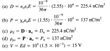
Q17) The electric field intensity in polystyrene ( r = 2.55) filling the space between the plates of a parallel-plate capacitor is 10 k V / m. The distance between the plates is 1.5 mm.
Calculate:
(a) D
(b) P
(c) The surface charge density of free charge on the plates
(d) The surface density of polarization charge
(e) The potential difference between the plates
A17)
Q18) A dielectric cube of side L and center at the origin has a radial polarization given by P = ar, where a is a constant and r = xax + yay + zaz. Find all bound charge densities and show explicitly that the total bound charge vanishes.
A18)
For each of the six faces of the cube, there is a surface charge ρps. For the face located at x = L/2,

The total bound surface charge is

The bound volume charge density is given by
ρpv =  .P = -(a+a+a)=-3a
And the total bound volume charge is
Qv =  dv =-3a
  =-3aL3
Hence the total charge is
Qr= QS + Qv = 3aL3 -3aL3 =0
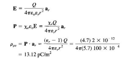
Q19) A dielectric sphere ( r = 5.7) of radius 10 cm has a point charge 2 pC placed at its center.
Calculate:
(a) The surface density of polarization charge on the surface of the sphere
(b) The force exerted by the charge on a -4-pC point charge placed on the sphere.
A19)
a) We apply Coulomb's or Gauss's law to obtain
(b) Using Coulomb's law, we have

Q20) Discuss Uniqueness Theorems?
A20)
Consider a volume within which the charge density is equal to zero. Suppose that the value of the electrostatic potential is specified at every point on the surface of this volume. The first uniqueness theorem states that in this case the solution of Laplace's equation is uniquely defined.
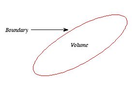
Figure: First Uniqueness Theorem
To proof the first uniqueness theorem we will consider what happens when there are two solutions V1 and V2 of Laplace's equation in the volume shown in Figure. Since V1 and V2 are solutions of Laplace's equation we know that
 =0
=0
 =0
=0
Since both V1 and V2 are solutions, they must have the same value on the boundary. Thus V1 = V2 on the boundary of the volume. Now consider a third function V3, which is the difference between V1 and V2
 =
= -
-
The function V3 is also a solution of Laplace's equation. This can be demonstrated easily:
 =
= -
-  =0
=0
The value of the function V3 is equal to zero on the boundary of the volume since V1 = V2 there. However, property 2 of any solution of Laplace's equation states that it can have no local maxima or minima and that the extreme values of the solution must occur at the boundaries. Since V3 is a solution of Laplace's equation and its value is zero everywhere on the boundary of the volume, the maximum and minimum value of V3 must be equal to zero. Therefore, V3 must be equal to zero everywhere. This immediately implies that
V1 = V2
This proves that there can be no two different functions V1 and V2 that are solutions of Laplace's equation and satisfy the same boundary conditions. Therefore, the solution of Laplace's equation is uniquely determined if its value is a specified function on all boundaries of the region. This also indicates that it does not matter how you come by your solution: if (a) it is a solution of Laplace's equation, and (b) it has the correct value on the boundaries, then it is the right and only solution.
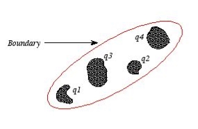
Figure: Boundary
The first uniqueness theorem can only be applied in those regions that are free of charge and surrounded by a boundary with a known potential (not necessarily constant). In the laboratory the boundaries are usually conductors connected to batteries to keep them at a fixed potential.
In many other electrostatic problems we do not know the potential at the boundaries of the system. Instead we might know the total charge on the various conductors that make up the system (note: knowing the total charge on a conductor does not imply a knowledge of the charge distribution ρ since it is influenced by the presence of the other conductors).
In addition to the conductors that make up the system, there might be a charge distribution ρ filling the regions between the conductors. For this type of system the first uniqueness theorem does not apply.
The second uniqueness theorem states that the electric field is uniquely determined if the total charge on each conductor is given and the charge distribution in the regions between the conductors is known.
The proof of the second uniqueness theorem is similar to the proof of the first uniqueness theorem.
Suppose that there are two fields  and
and  that are solutions of Poisson's equation in the region between the conductors. Thus
 .
. =
= 
 .
. =
= 
Where ρ is the charge density at the point where the electric field is evaluated. The surface integrals of  and
and  , evaluated using a surface that is just outside one of the conductors with charge Qi, are equal to
  . Thus
 =
= 
 =
= 
The difference between and
and  , So
, So
 =
=  -
- 
Satisfies the following equations:
 .
. =
=  .
. -
-  .
.
 -
-  =0
=0
 =
=  -
-  =
=  -
-  =0
=0
Consider the surface integral of  , integrated over all surfaces (the surface of all conductors and the outer surface). Since the potential on the surface of any conductor is constant, the electrostatic potential associated with
 and
and  , must also be constant on the surface of each conductor.
Therefore,  =
= -
- will also be constant on the surface of each conductor.
The surface integral of  over the surface of conductor i can be written as
 =
= 
 =0
=0
Since the surface integral of  over the surface of conductor i is equal to zero, the surface integral of
  over all conductor surfaces will also be equal to zero. The surface integral of
  over the outer surface will also be equal to zero since
  on this surface. Thus
 =0
=0
The surface integral  of can be rewritten using Green's identity as
0 =  = -
= -  =
= 
= -  = -
= -  =0
=0
Where the volume integration is over all space between the conductors and the outer surface. Since is always positive, the volume integral of
  can only be equal to zero if
  everywhere. This implies immediately that
 , everywhere, and proves the second uniqueness theorem.