Unit - 5
Boundary conditions, Maxwell’s equation and wave propagation
Q1) Derive electromagnetic wave equation?
A1)
Wave is nothing but a pattern of disturbance which propagates and carry energy with it. You can produce a wave on a rope by moving one end of the rope up and down. The wave produces on rope needs a medium to propagate and here medium is rope itself. This type of waves is known as mechanical waves. But in the case of Electromagnetic waves, they don't need a medium to propagate. Electromagnetic waves are waves that are created as a result of variations of electric field and a magnetic field. Or we can say that Electromagnetic waves are nothing but changing magnetic and electric fields. Electromagnetic waves are also known to be solutions of Maxwell's equations. And Maxwell's equations are the fundamental equations of electrodynamics. Electromagnetic waves can transmit energy and travel through a vacuum.
Light waves are examples of electromagnetic waves. Generally, Electromagnetic waves are shown by a sinusoidal graph.
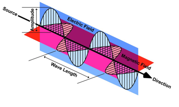
Figure: Electromagnetic waves
As shown in figure Electromagnetic waves consist of time-varying electric and magnetic fields and they are perpendicular to each other and these both fields are also perpendicular to the direction of propagation of waves.
Maxwell’s four equations are given by
∇·E = ρ/ε0 (1)
∇×E = −∂B/∂t (2)
∇×H = J + ∂D/∂t (3)
∇·B = 0 (4)
These equations illustrate the unique coexistence in nature of the electric field and the magnetic field. The first two equations give the value of the given flux through a closed surface, and the second two equations give the value of a line integral around a loop. In this notation,
∇=(∂/∂x, ∂/∂y, ∂/∂z)
E is the electric vector
B is the magnetic induction
ρ is the electric charge density
j is the electric current density
ε0 is the permittivity of free space
c is the speed of light.
In addition to Maxwell equations, the following identities are useful:
J = σE (5)
D = εE (6)
B = μH (7)
Here,
D is the electric displacement
H is the magnetic vector
σ is the specific conductivity
ε is the dielectric constant (or permittivity)
μ is the magnetic permeability
Free space or non-conducting medium. We know that non conducting medium means no current so conductivity is zero i.e. σ=0
So current density J=σE will also become zero as σ=0 Also free space means no charges which leads to ρ=0. These points mentioned below.
(a) No condition current i.e σ=0, thus J=0 ( J=σE)
(b) No charges (i.e ρ=0)
For the case of no charges or currents, that is, j = 0 and ρ = 0, and a homogeneous medium. Using these the Maxwell equation can rewritten as
∇.D=0 or ∇.E=0 as ρ=0 (12)
∇ x E= -dB/dt or ∇ x E= -μ dH/dt because B = μH (13)
∇ x H=d D/dt or ∇ x H = ε dE/dt (J=0) and D = εE (14)
∇.B=0 (15)
WAVE EQUATION IN TERMS OF ELECTRIC FIELD INTENSITY, E
Now taking curl of second Maxwell’s equation (13) ,we get
∇ x(∇ x E)=- μ d/dt (∇ x H)
Applying standard vector identity, that is [∇ *(∇*E)=∇(∇.E)-∇2E] on left hand side of above equation, we get
∇ (∇ .E)-∇2E= -μ d/dt (∇ x H) (16)
Substituting equations (13) and (14) in equations (16) ,we get
-∇2E= – με d/dt (dE/dt)
Or ∇2E=με d 2 E/dT2 (17)
Equation (17) is the required wave equation in terms of electric field intensity, E for free space . This is the law that E must obey.
WAVE EQUATION IN TERMS OF MAGNETIC FIELD INTENSITY, H
Take curl of fourth Maxwell’s equation (14) ,we get
∇x(∇xH)=ε d/dt(∇xE)
Applying standard vector identity that is
[∇*(∇*H)=∇ (∇.H)-∇2H]
On left side of above equation , we get
∇(∇.H)-∇2H= ε d/dt(∇xE) (18)
Substituting equations (14) and (13) in equation(18) ,we get
-∇2H= – μεd/dt(dH/dt)
Or
∇2H=με d2H/dt2 (19)
Equations (19) is the required wave equation in terms of magnetic field intensity, H and this is the law that H must obey
For vacuum μ=μ0 and ε=ε0, equations (17) and (19) will become
∇2 E=μ0ε0 d2E/dt2 (20)
And ∇2H= μ0ε0 d2H/dt2 (21)
This leads to an expression for the velocity of propagation
From equation both equations (20) and (21) have the form of the general wave equation for a wave

(x,t) traveling in the x direction with speed v. Equating the speed with the coefficients, we derive the speed of electric and magnetic waves, which is a constant that we symbolize with “c”
It is useful to note that in vacuum
c2=1/ε0μ0
Where μ0 is the permeability of free space

Let us rewrite the equation (20) and (21) for one dimension.
Or d 2 E/dx2 = μ0ε0 d 2 E/dt2 (22)
d2H/dx2 = μ0ε0 d2H/dt2 (23)
The simplest solutions to the differential equations (22) and (23) are sinusoidal wave functions:
E(x) = Emax cos(kx-t) (24)
B(x) = Bmax cos(kx-t) (25)
Where k = 2π/λ is the wavenumber , ω = 2πƒ is the angular frequency, λ is the wavelength, f is the frequency and ω /k=f=v= c.
Q2) Given E = 10 sin (t-y) ay V/m, in free space, determine D, B and H.
A2)
E = 10 sin (t-y) ay, V/m
D =0E,
0= 8.854 x 10⁻¹² F/m
D = 100sin (t-y) ay, C/m2
Second Maxwell’s equation is
x E = -B
That is,
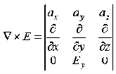
Or

As Ey= 10 sin (t-z) V/m
 = 0
= 0
Now,x E becomes
x E = -  ax
ax
= 10 cos (t-z) ax
= - 


Q3) If the electric field strength, E of an electromagnetic wave in free space is given by
E = 2 cos (t -  ) ay V/m,
Find the magnetic field, H
A3)
We have
B/t =-x E
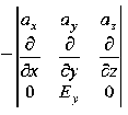


Thus

Also


Q4) For a long solenoid the magnetic field strength within the solenoid is given by the equation B=5.0t T, where t is time in seconds. If the induced electric field outside the solenoid is 11 V/m a distance 2.0 m from the axis of the solenoid, find the radius of the solenoid.
A4)
Given
When there is a changing magnetic field through a coil, it causes an induced emf in the coil, which is based on the Faraday's law of electromagnetic induction. Further, the induced emf is related to the induced electric field along the circumference of the coil.
Magnetic field inside the solenoid, B =5.0×t T
Induced electric field at radial distance (from the axis of solenoid) r = 2.0 m is E =11 V/m
Radius (R) of solenoid =?
The induced electric field at the radial distance r from the axis of the solenoid is expressed as:
E×(2πr) =
E×(2πr) =
E×(2×r) =R2
E×(2×r) = R2
11×(2×2) =R2×5
R= 2.966  3.0 m
3.0 m
Q5) A coil has 1000 turns and 500 cm2 as it's area. The plane of the coil is placed at right angles to a magnetic induction field of 2×10⁻⁵ Wb/m2. The coil is rotated through 1800 in 0.2 seconds. What is the average emf induced in the coil (in milli volts)?
A5)
The induced emf will be given by
Emf=
=
=
=
=10×10−3V=10 mV
Q6) In a uniform magnetic field of induction B, a wire in the form of semicircle of radius r rotates about the diameter of the circle with angular velocity ω. If the total resistance of the circuit is R, then find the mean power generated per period of rotation.
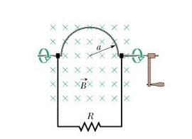
A6)
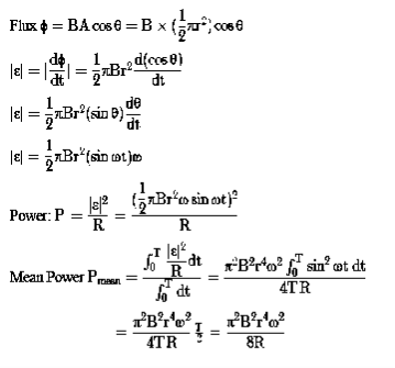
Q7) Discuss Faraday’s law of electromagnetic induction?
A7)
Faraday’s law of electromagnetic induction (referred to as Faraday’s law) is a basic law of electromagnetism predicting how a magnetic field will interact with an electric circuit to produce an electromotive force (EMF). This phenomenon is known as electromagnetic induction.
Faraday’s law states that a current will be induced in a conductor which is exposed to a changing magnetic field. Lenz’s law of electromagnetic induction states that the direction of this induced current will be such that the magnetic field created by the induced current opposes the initial changing magnetic field which produced it. The direction of this current flow can be determined using Fleming’s right-hand rule.
Let us understand Faraday’s law by faraday‘s experiment.
FARADAY’S EXPERIMENT
In this experiment, Faraday takes a magnet and a coil and connects a galvanometer across the coil. At starting, the magnet is at rest, so there is no deflection in the galvanometer i.e. the needle of the galvanometer is at the center or zero position. When the magnet is moved towards the coil, the needle of the galvanometer deflects in one direction.
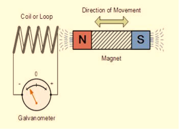
Figure: Faraday’s law of electromagnetic induction
When the magnet is held stationary at that position, the needle of galvanometer returns to zero position. Now when the magnet moves away from the coil, there is some deflection in the needle but opposite direction, and again when the magnet becomes stationary, at that point respect to the coil, the needle of the galvanometer returns to the zero position.
Similarly, if the magnet is held stationary and the coil moves away, and towards the magnet, the galvanometer similarly shows deflection. It is also seen that the faster the change in the magnetic field, the greater will be the induced EMF or voltage in the coil.
Let us take a look at the following table. This table is showing the observation of faraday’s experiment.
Position of magnet | Deflection in galvanometer |
Magnet at rest | No deflection in the galvanometer |
Magnet moves towards the coil | Deflection in galvanometer in one direction |
Magnet is held stationary at same position (near the coil) | No deflection in the galvanometer |
Magnet moves away from the coil | Deflection in galvanometer but in the opposite direction |
Magnet is held stationary at the same position (away from the coil) | No deflection in the galvanometer |
CONCLUSION
From this experiment, Faraday concluded that whenever there is relative motion between a conductor and a magnetic field, the flux linkage with a coil changes and this change in flux induces a voltage across a coil.
Michael Faraday formulated two laws on the basis of the above experiments. These laws are called Faraday’s laws of electromagnetic induction.
FARADAY’S FIRST LAW
Any change in the magnetic field of a coil of wire will cause an emf to be induced in the coil. This emf induced is called induced emf and if the conductor circuit is closed, the current will also circulate through the circuit and this current is called induced current.
Method to change the magnetic field:
- By moving a magnet towards or away from the coil
- By moving the coil into or out of the magnetic field
- By changing the area of a coil placed in the magnetic field
- By rotating the coil relative to the magnet
FARADAY’S SECOND LAW
It states that the magnitude of emf induced in the coil is equal to the rate of change of flux that linkages with the coil. The flux linkage of the coil is the product of the number of turns in the coil and flux associated with the coil.
According to Faraday’s law of electromagnetic induction, the rate of change of flux linkage is equal to induced emf.
 ………..(9)
Considering Lenz’s Law
Where:
- Flux Φ in Wb = B.A
- B = magnetic field strength
- A = area of the coil
FACTORS ON WHICH INDUCED EMF DEPEND
- By increasing the number of turns in the coil i.e. N, from the formulae derived above it is easily seen that if the number of turns in a coil is increased, the induced emf also gets increased.
- By increasing magnetic field strength i.e. B surrounding the coil- Mathematically, if magnetic field increases, flux increases and if flux increases emf induced will also get increased. Theoretically, if the coil is passed through a stronger magnetic field, there will be more lines of force for the coil to cut and hence there will be more emf induced.
- By increasing the speed of the relative motion between the coil and the magnet – If the relative speed between the coil and magnet is increased from its previous value, the coil will cut the lines of flux at a faster rate, so more induced emf would be produced.
Q8) Derive a relation for electric field due to a dipole on the axial line?
A8)
Electric field due to an electric dipole at points on the axial line
Consider an electric dipole placed on the x-axis as shown in Figure 6. A point C is located at a distance of r from the midpoint O of the dipole along the axial line.
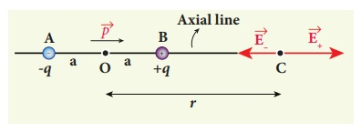
Figure: Electric field of the dipole on the axial line
The electric field at a point C due to +q is
 ………(1)
Since the electric dipole moment vector  is from –q to +q and is directed along BC, the above equation is rewritten as
 ………(2)
Where p ^ is the electric dipole moment unit vector from –q to +q.
The electric field at a point C due to –q is
 ………(3)
Since +q is located closer to the point C than –q,  , is stronger than
  , Therefore, the length of the
  vector is drawn larger than that of
  vector.
The total electric field at point C is calculated using the superposition principle of the electric field.
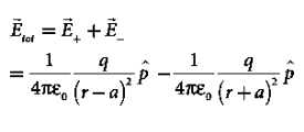 ………(4)
 ………(5)
 ………(6)
Note that the total electric field is along  , since +q is closer to C than –q.
The direction of  , is shown in Figure.
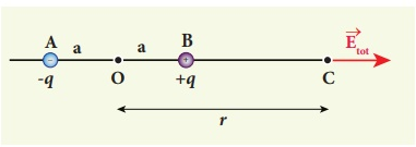
Figure: Total electric field of the dipole on the axial line
If the point C is very far away from the dipole then (r >> a). Under this limit the term ( r2 − a2 )2 ≈ r4 . Substituting this into equation (6), we get
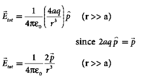 ………(7)
If the point C is chosen on the left side of the dipole, the total electric field is still in the direction of  .
.
Q9) What do you meant by gradient? Discuss its physical significance?
A9)
The gradient is a fancy word for derivative, or the rate of change of a function. It’s a vector (a direction to move) that
- Points in the direction of greatest increase of a function
- Is zero at a local maximum or local minimum (because there is no single direction of increase)
The term "gradient" is typically used for functions with several inputs and a single output (a scalar field). Yes, you can say a line has a gradient (its slope), but using "gradient" for single-variable functions is unnecessarily confusing. Keep it simple.
“Gradient” can refer to gradual changes of colour, but we’ll stick to the math definition. You’ll see the meanings are related.
PHYSICAL SIGNIFICANCE OF GRADIENT
A scalar field may be represented by a series of level surfaces each having a stable value of scalar point function θ. The θ changes by a stable value as we move from one surface to another. These surfaces are known as Gaussian surfaces. Now let the two such surfaces are very close together, be represented by two scalar point functions and (θ + d θ). Let ‘r’ and (r + d θ) be the position vectors of points A and B, on the surfaces θ and (θ + d θ) correspondingly with respect to an origin 0 as shown in Figure. Clearly, the vector AB will be dr. Let the least detachment between the two surfaces ‘dn’ be in the direction of unit usual vector n at A.
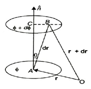
Figure: Physical significance of gradient
Dn = dr cos θ
= | n | dr | cos θ =n .dr
Dϕ = ∂ϕ/ dn =∂ϕ/dn n .dr…… (1)
Since the continuous scalar function defining the level surfaces (Gaussian surfaces) has a value θ at point A (x, y, z) and (θ + dθ) at point (x + dx, y + dy, z + dz), we have
dϕ = ∂ ϕ/dx dx +dϕ/∂y + ∂ϕ/∂x dz
= (I ∂ϕ/∂x +j ∂ϕ/vy +k ∂ϕ/∂z) .(idx +jdy +kdz)
= ∆ ϕ. Dr … … (2)
From equations (1) and (2), equating the values of d θ,
We obtain ∆θ .dr =∆ ϕ= ∂ϕ/ ∂n n .dr
As dr is an arbitrary vector, we have
∆ϕ =∂ϕ/∂ n
Grad ϕ = ∂ ϕ/∂n n
Therefore, the gradient an of a scalar field at any point is a vector field, the scale of which is equal to the highest rate of increase of θ at that point and the direction of it is similar as that of usual to the level surface at that point.
Its physical significance of grad can be understand in terms of the graph of some function z = f(x, y), where f is a reasonable function – say with continuous first partial derivatives. In this case we can think of the graph as a surface whose points have variable heights over the xy – plane. An illustration is given below.
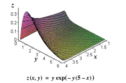
Figure: Graph of a surface whose points have variable heights over the xy – plane.
If, say, we place a marble at some point (x, y) on this graph with zero initial force, its motion will trace out a path on the surface, and in fact it will choose the direction of steepest descent. This direction of steepest descent is given by the negative of the gradient of f. One takes the negative direction because the height is decreasing rather than increasing.
Using the language of vector fields, we may restate this as follows: For the given function f(x, y), gravitational force defines a vector field F over the corresponding surface z = f(x, y), and the initial velocity of an object at a point (x, y) is given mathematically by –∇f(x, y). The gradient also describes directions of maximum change in other contexts. For example, if we think off as describing the temperature at a point(x, y), then the gradient gives the direction in which the temperature is increasing most rapidly.
Q10) Give Physical Significance of Maxwell’s equation?
A10)
Physical significance of Maxwell’s Ist equation
∇·E = ρ/ε0
According to this total electric flux through any closed surface is 1/0 times the total charge enclosed by the closed surfaces, representing Gauss's law of electrostatics, As this does not depend on time, it is a steady state equation. Here for positive , divergence of electric field is positive and for negative divergence is negative. It indicates that is scalar quantity.
Physical significance of Maxwell’s 2nd equation
∇·B = 0
It represents Gauss law of magnetostatic as ∇·B = 0 resulting that isolated magnetic poles or magnetic monopoles cannot exist as they appear only in pairs and there is no source or sink for magnetic lines of forces. It is also independent of time i.e. steady state equation.
Physical significance of Maxwell’s 3rd equation
∇×E = −∂B/∂t
It shows that with time varying magnetic flux, electric field is produced in accordance with Faraday is law of electromagnetic induction. This is a time dependent equation.
Physical significance of Maxwell’s 4th equation
∇×H = J + ∂D/∂t
This is a time dependent equation which represents the modified differential form of Ampere's circuital law according to which magnetic field is produced due to combined effect of conduction current density and displacement current density.
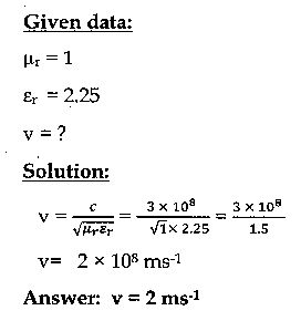
Q11) If the relative permeability and relative permittivity of the medium is 1.0 and 2.25, respectively. Find the speed of the electromagnetic wave in this medium.
A11)
Q12) Discuss Maxwell’s equations?
A12)
Maxwell equations are of fundamental importance since they describe the whole of classical electromagnetic phenomena.
Maxwell's Equations are a set of 4 complicated equations that describe the world of electromagnetics. These equations describe how electric and magnetic fields propagate, interact, and how they are influenced by objects.
Maxwell was one of the first to determine the speed of propagation of electromagnetic (EM) waves was the same as the speed of light - and hence to conclude that EM waves and visible light were really the same thing.
These equations are rules the universe uses to govern the behaviour of electric and magnetic fields. A flow of electric current will produce a magnetic field. If the current flow varies with time (as in any wave or periodic signal), the magnetic field will also give rise to an electric field. Maxwell's Equations shows that separated charge (positive and negative) gives rise to an electric field - and if this is varying in time as well will give rise to a propagating electric field, further giving rise to a propagating magnetic field.
From a classical perspective, light can be described as waves of electromagnetic radiation. As such, Maxwell equations are very useful to illustrate a number of the characteristics of light including polarization.
We are just to stating these equations without derivation. Since our goal is simply to apply them, the usual approach will be followed.
Maxwell’s first equation (Gauss' Law for Electric Fields)
Gauss' Law is the first of Maxwell's Equations which dictates how the Electric Field behaves around electric charges. Gauss' Law can be written in terms of the Electric Flux Density and the Electric Charge Density as:
∇·E = ρ/ε0
0r
∇·D = ρ
Hence, Gauss' law is a mathematical statement that the total Electric Flux exiting any volume is equal to the total charge inside. Hence, if the volume in question has no charge within it, the net flow of Electric Flux out of that region is zero. If there is positive charge within a volume, then there exists a positive amount of Electric Flux exiting any volume that surrounds the charge. If there is negative charge within a volume, then there exists a negative amount of Electric Flux exiting (i.e. the Electric Flux enters the volume).
Maxwell’s second equation (Faraday's Law)
Faraday figured out that a changing Magnetic Flux within a circuit (or closed loop of wire) produced an induced EMF, or voltage within the circuit. Maxwell gives his second equation from this.
Faraday's Law tells us that a magnetic field that is changing in time will give rise to a circulating E-field. This means we have two ways of generating E-fields - from Electric Charges (or flowing electric charge, current) or from a magnetic field that is changing.
∇×E = −∂B/∂t (2)
Maxwell’s third equation (Ampere's Law)
Ampere's Law tells us that a flowing electric current gives rise to a magnetic field that circles the wire. In addition to this, it also says that an Electric Field that is changing in time gives rise to a magnetic field that encircles the E-field - this is the Displacement Current term that Maxwell himself introduced.
This means there are 2 ways to generate a solenoidal (circulating) H-field - a flowing electric current or a changing Electric Field. Both give rise to the same phenomenon.
The modified form of Ampere's Law s given by Maxwell’s third equation
∇×H = J + ∂D/∂t
Maxwell’s four equation (Gauss' Magnetism law)
We know that Gauss' Law for Electric Fields states that the divergence of the Electric Flux Density D is equal to the volume electric charge density. But the second equation, Gauss' Magnetism law states that the divergence of the Magnetic Flux Density (B) is zero.
Why? Why isn't the divergence of B equal to the magnetic charge density?
Well - it is. But it just so happens that no one has ever found magnetic charge - not in a laboratory or on the street or on the subway. And therefore, until this hypothetical magnetic charge is found, we set the right side of Gauss' Law for Magnetic Fields to zero:
∇·B = 0
Now, you may have played with magnets when you were little, and these magnetic objects attracted other magnets similar to how electric charges repel or attract like electric charges. However, there is something special about these magnets - they always have a positive and negative end. This means every magnetic object is a magnetic dipole, with a north and South Pole. No matter how many times you break the magnetic in half, it will just form more magnetic dipoles. Gauss' Law for Magnetism states that magnetic monopoles do not exist - or at least we haven't found them yet.
Maxwell’s four equations are given by
∇·E = ρ/ε0 (1)
∇×E = −∂B/∂t (2)
∇×H = J + ∂D/∂t (3)
∇·B = 0 (4)
These equations illustrate the unique coexistence in nature of the electric field and the magnetic field. The first two equations give the value of the given flux through a closed surface, and the second two equations give the value of a line integral around a loop. In this notation,
∇=(∂/∂x, ∂/∂y, ∂/∂z)
E is the electric vector
B is the magnetic induction
ρ is the electric charge density
j is the electric current density
ε0 is the permittivity of free space
c is the speed of light.
In addition to Maxwell equations, the following identities are useful:
J = σE (5)
D = εE (6)
B = μH (7)
Here,
D is the electric displacement
H is the magnetic vector
σ is the specific conductivity
ε is the dielectric constant (or permittivity)
μ is the magnetic permeability
Q13) Define Gauss’s law? What is the value of Gauss’s law in free space?
A13)
The law was published posthumously in 1867 as part of a collection of work by the famous German mathematician Carl Friedrich Gauss.
Gauss’s law for the electric field describes the static electric field generated by a distribution of electric charges.
It states that the electric flux through any closed surface is proportional to the total electric charge enclosed by this surface.
Let’s calculate the electric flux through a spherical surface around a positive point charge q, since we already know the electric field in such a situation. Recall that when we place the point charge at the origin of a coordinate system, the electric field at a point P that is at a distance r from the charge at the origin is given by

 is the radial vector from the charge at the origin to the point P. We can use this electric field to find the flux through the spherical surface of radius r, as shown in Figure.
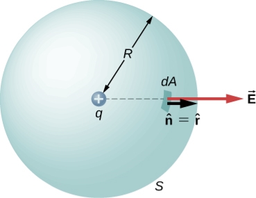
Figure: A closed spherical surface surrounding a point charge q.
Then we apply Φ=∫S  ⋅
⋅ dA
dA
To this system and substitute known values. On the sphere,  and r=R
So for an infinitesimal area dA,
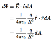
We now find the net flux by integrating this flux over the surface of the sphere

Where the total surface area of the spherical surface is 4πR2. This gives the flux through the closed spherical surface at radius r as
Φ=q/ϵ0
A remarkable fact about this equation is that the flux is independent of the size of the spherical surface. This can be directly attributed to the fact that the electric field of a point charge decreases as 1/r2 with distance, which just cancels the r2 rate of increase of the surface area.
Gauss' Law is the first of Maxwell's Equations which dictates how the Electric Field behaves around electric charges. Gauss' Law can be written in terms of the Electric Flux Density and the Electric Charge Density as:
∇·E = ρ/ε0
0r
∇·D = ρ
Hence, Gauss' law is a mathematical statement that the total Electric Flux exiting any volume is equal to the total charge inside. Hence, if the volume in question has no charge within it, the net flow of Electric Flux out of that region is zero. If there is positive charge within a volume, then there exists a positive amount of Electric Flux exiting any volume that surrounds the charge. If there is negative charge within a volume, then there exists a negative amount of Electric Flux exiting (i.e. the Electric Flux enters the volume).
In integral form

in differential form
∇·E = ρ/ε0
But in free space charge ρ is zero so ∇·E =0
Q14) Derive a relation for electric field due to a dipole on the axial line?
A14)
Electric field due to an electric dipole at a point on the equatorial plane
Consider a point C at a distance r from the midpoint O of the dipole on the equatorial plane as shown in Figure.
Since the point C is equidistant from +q and –q, the magnitude of the electric fields of +q and –q are the same. The direction of  is along BC and the direction of
  is along CA.
  and
and  are resolved into two components; one component parallel to the dipole axis and the other perpendicular to it. The perpendicular components |
 | sinθ and |
 | sinθ are oppositely directed and cancel each other. The magnitude of the total electric field at point C is the sum of the parallel components of
  + and
+ and  and its direction is along -
 as shown in the Figure 8.
 ………(8)
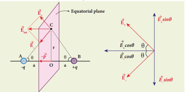
Figure: Electric field of the dipole at a point on the equatorial plane
The magnitudes  + and
+ and  are the same and are given by
 ………(9)
By substituting equation (9) into equation (8), we get
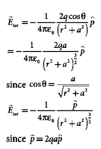 ………(10)
At very large distances (r>>a), the equation (10) becomes
 ………(11)
Q15) Derive expression for plane wave in good conductor?
A15) A uniform plane wave with x-directed electric field is normally incident upon a perfectly conducting plane at z =0, as shown in Figure. The presence of the boundary gives rise to a reflected wave that propagates in the -z direction. There are no fields within the perfect conductor. The known incident fields traveling in the +z direction can be written as


While the reflected fields propagating in the -z direction are similarly


Where in the lossless free space

The minus sign difference in the spatial exponential phase factors of (1) and (2) as the waves are traveling in opposite directions. The amplitude of incident and reflected magnetic fields are given by the ratio of electric field amplitude to the wave impedance.
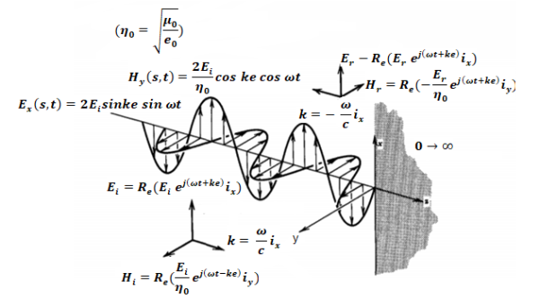
The negative sign in front of the reflected magnetic field for the wave in the -z direction arises because the power flow S, = E, x H, in the reflected wave must also be in the -z direction. The total electric and magnetic fields are just the sum of the incident and reflected fields. The only unknown parameter E, can be evaluated from the boundary condition at z =0 where the tangential component of E must be continuous and thus zero along the perfect conductor:
The total fields are the sum of incident and reflected fields

=
=

=
=
The electric and magnetic fields are 90* out of phase with each other both in time and space.
Q16) Derive the solution for Maxwells equation for uniform plane wave?
A16) The sources of time varying electromagnetic fields are time varying charges and currents, whether man-made or naturally occurring. However, examination of Maxwell’s equations shows that, even in empty space (with no sources), and fields cause each other. This means that, although these fields must originate in source regions, they can propagate through source-free regions. Because solutions in source regions are very hard to obtain, let us consider what kind of fields can exist in source-free regions.

These equations are still very complicated (4 different partial derivatives). Let’s try to find simple solutions. We do this by making assumptions. After finding simplest solutions, we:
(i) Find what kind of source would generate this type of field (waves).
(ii) Show that these simple solutions are useful approximations to real electromagnetic waves.
Assumption for Solution:
Can we find a solution such that:
1.) No variation exists in x and y directions.
2.)  or
or  also is oriented along one of the axes.
Ampere’s Law becomes:

Or, with our assumptions:

Compare for transmission line:

In a similar manner,
 ………….(1)
Faraday’s Law becomes:
 ………….(2)
Thus, if  is only in the
  direction, then is only in the. If we differentiate (2) with respect to z, we get:

Substitute from (2),

We get

This is called the wave equation.
Compare for transmission line: (same).

We will assume dielectric media; lossless:

Dimensional analysis:


In the units we are using:
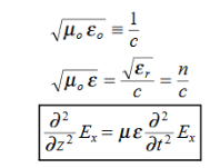
By exactly the same method, we also get:
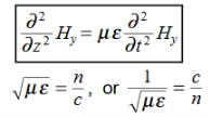
For example, the same equation is true for  and
and  . Thus,
  and
and  must have the same type of functional dependence. This wave equation still has many possible solutions. In fact, it can be shown by direct substitution that

Are the solutions

t is important to note that f1 and f2 can be any function.
The field we find directly from the equation:

Suppose
 …………(3)
Differentiate (3) with respect to z
 …………(4)
Integrate with respect to time
 …………(5)

This leads to a new quantity that relates the electric and magnetic fields:


Rewriting:
Units of  =
=  =
=  = Ω
= Ω
 0 = Impedance of free space =
  =377 Ω
 = impedance of a lossless dielectric =
  =
= =
= 
Note that  and
and  are in time phase and space quadrature
The directions of the vectors are such that:

This vector  , always points in the direction of propagation. These types of waves are called Uniform Plane Electromagnetic Waves.
“Plane” refers to the fact that, at any instant in time, the surfaces of constant phase are planes (here, constant).
“Uniform” means no variation in transverse direction. The wave derived here is one oscillating at a single frequency. The frequency is determined by the source. If the source has multiple frequencies, so will the wave. In communications, modulating a carrier wave results in multiple frequencies. But before we can study such fields, we must thoroughly understand single frequency sinusoidal waves.