Unit - 1
Evolution of Structure of Power Systems
Q1) Explain the types of DC links in HVDC transmission?
A1)
Types of DC links-
1) Mono polar link

It has only one energized conductor normally of negative polarity and uses ground or sea water as a return path.
It may be noted that earth as much lower resistance to DC as compared to AC.
Negative polarity is preferred on overhead lines due to less radio interference.
2) Bipolar link
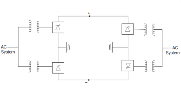
This link has two conductors positive and negative at the same magnitude 650 KV. At each terminal two conductors of equal rated voltage are connected in series on the DC side.
The neutral points are grounded at one or both ends. If both neutrals are grounded, two poles operate independently.
If current in two conductors are equal the ground current is zero.
If one conductor has a fault, the Other conductor along with ground return can supply half the rated load.
A bipolar line can be operated as monopolar line in an emergency.
3) Homopolar link
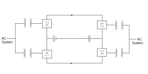
In homo polar link two or more conductors all having same polarity (usually negative) as Corona loss of radio interference reduced and is always operate with ground as the return.
If one of the conductors develops a fault the converter equipment can be reconnect so that healthy conductor can supply more than 50% of the rated power.
A 2 conductor DC line is more reliable than 3 conductor AC line because at the event of fault on one conductor. The other conductor can continue to operate with ground return during the fault current. Therefore, DC is reliable.
If a homo polar DC line is compared with double circuit 3 AC line, the DC line cost would be about 45% less than the AC line.
Q2) Write Technical and economic advantage of HVDC over HYDC
A2)
- DC line can carry as much power with two conductors as AC line with three conductors of the same size.
- Lessor number of conductor and insulator and therefore reduced conductor and insulator cost associated with transmission.
- When the Phase to phase clearance and lesser phase to ground clearance.
- Lighter and cheaper tower in case of HVDC.
- Less right of way(ROW) requirement in case of HYDC.
- Power losses are also reduced with DC as there are only two conductors (about 67%) as that of AC with same current capacity conductors.
- Absence of skin effect in case of DC is also beneficial in reducing power loss marginally.
- The dielectric losses in case of DC power cables are small.
- Lesser Corona loss of reduced radio and telephonic interference since the corona effect are less the choice of economical size of conductor with HVDC is possible.
- DC line don’t require compensation but the terminal equipment cost is increased due to presence of converters.
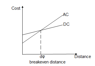
- AC tends to be more economical than DC for distance less than breakeven distance and costlier for longer distance.
- The breakeven distance can vary from 500 to 800 km.
Q3) List the advantages, disadvantages and limitations of HVDC transmission?
A3)
Advantages-
i) Corona loss, radio interference and audible emission are less
Ii) No reactive compensation of DC lines required.
Iii) Each conductor can be operated as an independent circuit.
Iv) There is easy reversibility and controllability of power flow through DC link.
v) No charging current and skin effect.
Vi) It is possible to bring more power into an AC system via a DC link without rising a fault level of CB ratings.
Vii) DC tables can be worked at Higher voltage gradient.
Viii) voltage regulation problem is less for DC
Ix) line losses are smaller
x) It can interconnect two rigid systems operating at different frequencies
Xi) Power losses are also reduced with DC as there are only two conductors (about 67% that of AC with same current capacity)
Disadvantages–
i) Harmonics are generated which require filters.
Ii) more frequent cleaning of insulators is required. Pollution affect DC more than AC.
Iii) There is no DC device which can perform excellent switching operation and ensure protection.
Iv) converters don't have overload capability
v) converters require considerable reactive power
Vi) No reactive power can be transmitted over DC link.
Vii) Installation of converters are complicated and DC switchgearis expensive.
Limitations-
i) Circuit breaker - cost of DC CBs are too high.
Ii) Transformers - doesn’t have x'mer to step up or step down the DC voltage levels.
Iii) Generation of harmonics - Both AC and DC harmonics generator. AC and DC filters are required to minimise harmonics thus cost increases.
Iv) Cooling of HVDC substation- effective cooling system is required to dissipate the heat.
v) System control - the system control is quite complex.
Applications-
i) Interconnection of system of the same frequency through zero length dc-link (back to back connection)
Ii) Interconnection between power systems
Iii) HVDC are used to evacuate power from the remote super power station to the load Centre situated several hundred kilometres away.
Iv) High power submarine distribution system feeders.
v) stabilizing AC system by modulating DC power flow.
Q4) Compare HVAD and HVAC systems?
A4)
HVAC | HVDC |
It stands for High Voltage Alternating Current. | It stands for High Voltage Direct Current. |
It uses a transformer for voltage conversion. | It uses solid-state semiconductor based converters for voltage conversion. |
The HVAC voltage conversion is simple & inexpensive. | The HVDC voltage conversion is complex & expensive. |
HVAC transmission requires a minimum of three conductors. | The HVDC requires only two conductors in bipolar & one conductor in monopolar transmission. |
The HVAC transmission is used for less than 600 Km distance. | The HVDC transmission is used for transmitting bulk power more than 600Km distance. |
It offers better flexibility allowing multiple tappings in the pathway. | It does not offer flexibility & transmit power from point to point. |
The effective power transmission capability is affected by reactive power losses. | There are no reactive power losses in HVDC transmission. |
The conductors are affected by corona losses. | The corona losses in HVDC are reduced by a factor of approximately 3. |
It requires a large diameter cable due to skin effect. | The current stays uniform in cable thus it can use comparatively smaller diameter cable. |
It wastes almost 30% of conductor capacity due to AC peak ratings while delivering average power. | It utilizes full conductor capacity due to the DC peak & average being the same value. |
The HVAC has a broader right-of-way. | The HVDC has a narrower right-of-way. |
The HVAC transmission requires tall sized towers. | The HVDC transmission requires a smaller tower. |
It is not preferred for submarine or underwater power transmission due to the stray capacitance of the cables. | The HVDC is preferred & used for submarine power transmission offshore. |
HVAC does not offer controllability. | It offers great controllability over the power flow, frequency control & dampening of power swings. |
The AC generates interference in the nearby communication lines. | The direct current does not generate any interference. |
The line arc may extinguish because of the voltage zero-crossing. | The arc will never get a chance to extinguish unless the power source is tripped. |
The HVAC circuit breakers are simple & cheaper because the arc will self-extinguish. | The HVDC circuit breakers are expensive & have complex design circuit to force the current to zero. |
The HVAC is best suitable for overhead power transmission at distances below 600 km which is economical. | The HVDC is used for long-distance bulk power transmission including underwater as well as the asynchronous interconnection between AC grids. |
Q5) What are recent trends in HVDC system and list some of the HVDC systems in India?
A5)
The basic element in HVDC converter is thyristor. Thyristors using about 150 mm diameter wafer have been developed.
Light triggered thyristor is also been developed
Now GTO are being used in some HVDC projects.
Advanced fully digital control systems are being used with optical fibres.
Future power systems will include a transmission mix of AC and DC future controllers would be more and more microcontroller-based which can be modified without requiring hardware changes and without bringing the entire system down.
While one controller is in action, the duplicate controller is there in case of sudden need.
In future it is expected that fibre system will be used to generate firing signal and the direct light fired thyristor would be employed for HVDC converter.
Solid state Technology due to which HVDC converter and MTDC system will play a greater role.
MTDC(Multi terminal DC links)
There is Kingsworth London multi terminal DC link. A MTDC network has no. Of rectifier and inverter station.
In three terminal HVDC link two converters can operate as a rectifier and the third as inverter. It can be reversed also i.e. 2 inverter and one rectifier, thus there is greater flexibility in operation.
HVDC Systems in India
Sr. No | System/Project | Year of Commissioned | Power Rating | Voltage |
1 | National HVDC project-stage-I | 1989 | 100 MW | 100 kV |
2 | National HVDC project-stage-II | 1999 | 200 MW | 200 kV |
3 | Rihand-Delhi | 1990 | 1500 MW |  |
4 | Chandrapur- Padghe | 1999 | 1500 MW |  |
Q6) What are various HVDC control methods explain them all?
A6)
Constant current control method-
It performs the following functions and operations-
- Measures the system current Id.
- Compare it with reference current Id.
- Amplifies the error signal.
- The o/p error signal controls
 in case of rectifier and ∂ in case of inverter in proper direction to reduce the error.
 - If the measured current is more then the reference
 may be increased. In case of rectifier to decrease the open circuit voltage of the rectifier.
 - The difference between the open circuit voltage of the rectifier and the inverter is decreased and the current is decreased proportionally.
- However in case of an inverter if the measured current is more than the reference current the open circuit voltage of the inverter must be increased instead of being decreased.
- If we consider inverter voltage to be negative which is usual, the same converter sometimes rectifiers at other inverter.
- The algebraic value of inverter voltage must be decreased as a rectifier and to accomplish this
 must be increased.
Constant ignition angle control method
The voltage Vdi from the rectifier circuit is given by
Vdi = Vcrcos -Id(Rcr +RL) and from inverter circuit
Vdi = Vcicos +IdRci
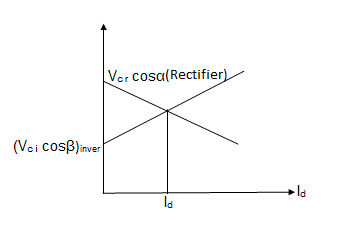
In order that current Id flows OCV of rectifier must be higher than OCV of inverter. The point of intersection (Id, Vdi) of these characteristic gives the operating point.
The inverter operation under such condition constant
a) Excitation angle may be larger.
b) Vdg dip in AC side.
c) Suppose that Normal current Id is flowing and that is so adjust that  as ahown in fig.
If now voltage on the AC side experience symmetrical dip assuming that the current does not change substantially, same current induces at reduce voltage this requires that the shaded areas.
A Stunt fault will not only reduce the commutating voltage but also increases or decreases the available commutation angle as shown in figure.
In case of dip in voltage on AC side, the rate of change of current maybe very large. That’s the fact that the large smoothing reactor are in the system.
This controller consists of separate computer for each group of thyristor connected to the same phase.
Each computer continuously computes and providing the signal for firing of thyristor.
The computer monitors the following quantities:
1) Amplitude of commutative voltage
2) Phase of commutating voltage
3) Magnitude of direct current.
Extinction Angle Control
The current controller is invariably of feedback type which is of PI type The extinction angle controller can be of predictive type or feedback type with IPC control. The predictive controller is considered to be less prone to commutation failure and was used in early schemes. The feedback control with PFC type of Equidistant Pulse Control overcomes the problems associated with IPC. The extinction angle, as opposed to current, is a discrete variable and it was felt the feedback control of gamma is slower than the predictive type. The firing pulse generation is based on the following equation
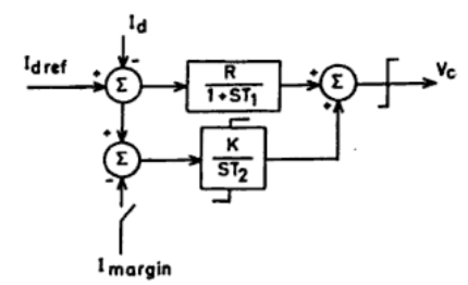

Where ecj is the commutation voltage across valve j and tn is the instant of its firing. In general, the prediction of firing angle is based on the equation
Βj = γref + µj
Where µj is the overlap angle of valve j, which is to be predicted based on the current knowledge of the commutation voltage and DC current. Under large disturbances such as a sudden dip in the AC voltage, signals derived from the derivative of voltage or DC current aid the advancing of delay angle for fast recovery from commutation failures.
Q7) Explain the components of HVDC system?
A7)
Components of HVDC transmission system
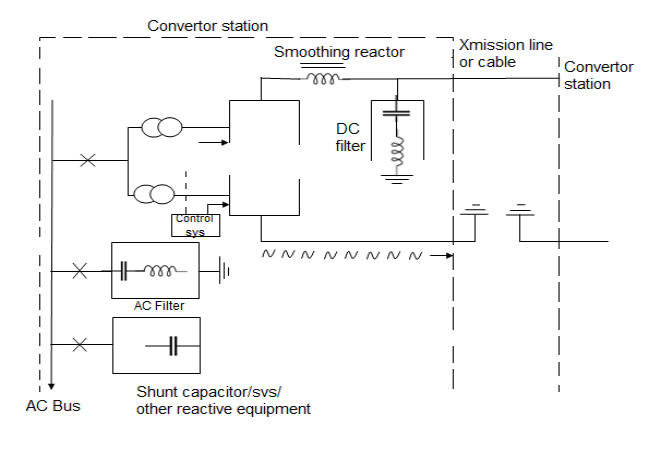
- Converter transformer- Transformers provide a suitable voltage ratio to achieve the desired direct voltage and Galvanic separation of the AC and DC systems.
The valve side windings are connected in Star and Delta with neutral point undergrounded. The leakage reaction of the transformer is chosen to limit the circuit current through any valve.
- Filters- 3 types of filters are used-
a) AC filter- they are used to provide low impedance shunt path for AC harmonic current.
b) AC filter- These are also same as AC filter used for filtering DC harmonics.
c) High frequency filters - these are connected between the converter x’mer of station AC bus to suppress any high frequency current.
Smoothing Reactor
It reduces the harmonic current in the DC line possible transient overcurrent.
It serves the following-
Ii) Smoothen the ripple in the direct current
Iii) Decreases the harmonic voltage of current in DC line.
Iv) Limit the fault current in DC line.
Q8) What is series MTDC system? Compare series and parallel MTDC system?
A8)
1) Series MTDC system- This is a natural extension of the two terminal system which is a series connected system. A three terminal MTDC system with a monopolar arrangement is shown as:
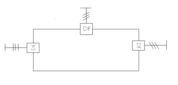
In one converter station would require either the disconnection of a bridge in all the stations or disconnection of the affected station.
Comparison of series and parallel MTDC system
i) High speed reversal of power is possible in series systems without mechanical switching. This is not possible in parallel systems.
Ii) The valve voltage rating in a series system is related to the power rating while the current rating in a parallel connected system is related to the power.
Iii) There are increased losses in the line and valves in series system in comparison to parallel systems.
Iv) Insulation coordination is a problem in series system as the voltage along the line varies.
v) The permanent fault in a line section would lead to complete shutdown in a series connected system while it would lead to only the shutdown of a converter station connected to the line section in a radial MTDC system.
Vi) The reduction in AC voltages and commutation failures in an inverter can lead to overloading of converters as current is transferred from other terminals in a parallel system.
Vii) The control and protection philosophy in a series MTDC system is a natural extension of that in a two terminals system. However, extension to parallel systems is not straight forward. It requires more communication system and also there are problems associated from commutation failures with parallel systems.
The series connection is appropriate for taps of rating less than 20% of the major inverter terminal, while parallel connection is more versatile and is expected to be used in AC systems.
Q9) Compare AC and DC transmission?
A9)
Comparison of ac and dc transmission
a) Economics of transmission
The cost of a transmission line includes the investment and operational costs. The investment includes cost of Right of way, transmission towers, conductors, insulators and terminal equipment. The operational costs include mainly the cost of losses.
For DC line at given power level requires less Tow, simpler and cheaper towers and reduced conductor and insulator costs as it has only two conductors.
The power losses are also reduced with DC as there are only two conductors (about 67% of that for AC with some current carrying capacity of conductors).
The absence of skin effect with DC is also beneficial in reducing power losses marginally.
The corona effect is also less significant on DC conductors than for AC and this also leads to the choice of economic size of conductors with DC transmission.
DC lines don’t require compensation but the terminal equipment costs are increased due to the presence of converters and filters.
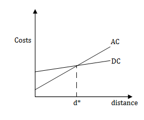
Where d* - break even distance
b) Technical performance
Stability limits-The power transfer in AC lines is dependent on the angle difference between the voltage phasors at the two ends. For a given power level, this angle increases with distance.
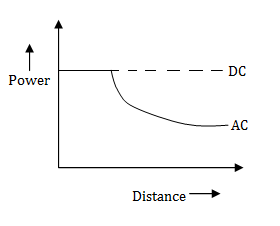
Voltage control - The reactive power requirements increases with the increase in the line lengths for AC transmission.
c) Reliability
The reliability of DC Transmission Systems is quite good and comparable to that of AC systems as both energy availability and transient stability of existing DC systems with thyristor valves is 95% or more.
Energy availability = 
Where equivalent outage time is the product of the actual outage time and fraction of system capacity loss due to outage.
Transient reliability= 
Transient reliability is a factor specifying the performance of HVDC systems during recordable faults on the associated AC systems.
Q10) What is a converter station and what are its components?
A10)
Converter Station- Here the conversions rom AC to DC (rectifier Station) and from DC to AC (inverter station) are performed. Typically, two 12 pulse converters units per pole are used.
a) Converter unit - This usually consists of two three phase converter bridges connected in series to form 12 pulse converters.
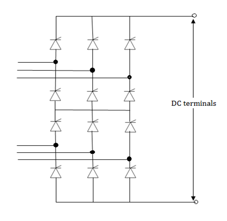
b) Converter Transformer- The converter transformer can have different configurations:
i) 3 phase two winding
Ii) Single phase 3 winding
Iii) single phase 2 winding
The valve side windings are connected in Star and Delta with neutral point ungrounded. On the AC side, the Transformers are connected in parallel with neutral grounded.
c) Filters- AC filters, DC filters and high frequency (RF/PLC) filters.
d) Reactive Power source- Converter stations require reactive power supply that is dependent on the active power loading. (about 50% to 60% of the active power). Part of this reactive power requirement is provided by AC filters. In addition, shunt capacitors, synchronous condensors and static vary systems are used.
e) Smoothing reactor- A sufficiently large series reactor is used on DC side to smooth DC current and also for protection.
f) DC switchgear- DC breakers or metallic return transfer breakers (MRTB) are used, if required for interruption of rated load currents.
Q11) Explain the working of 6-pulse converter?
A11)
The conversion from AC to DC and vice-versa is done in HVDC converter stations by using three phase bridge converters. The configuration of the bridge (also called Graetz circuit) is a six pulse converter and the 12 pulse converter is composed of two bridges in series supplied from two different (three-phase) transformers with voltages differing in phase by 30o.
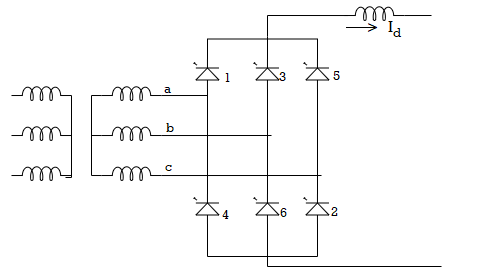
Pulse Number The pulse number of a converter is defined as the number of pulsations (cycles of ripple) of direct voltage per cycle of alternating voltage. The conversion from AC to DC involves switching sequentially different sinusoidal voltages onto the DC circuit.
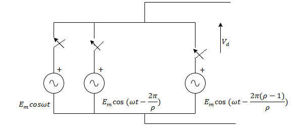
A valve can be treated as a controllable switch which can be turned ON at any instant, provided the voltage across it is positive. The output voltage Vd of the converter consists of a DC component and a ripple whose frequency is determined by the pulse number.
Choice of Converter Configuration
The configuration for a given pulse number is so chosen in such a way that the valve and transformer are used to the maximum.
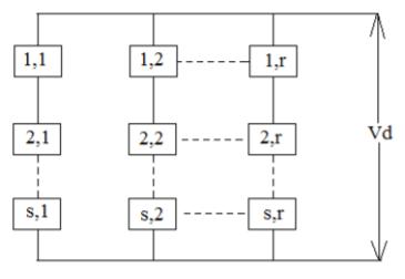
A converter configuration can be defined by the basic commutation group and the number of such groups connected in series and parallel. If there are ‘q’ valves in a basic commutation group and r of those are connected in parallel and s of them in series then, p = q r s
A commutation group is defined as the group of valves in which only one (neglecting overlap) conducts at a time.
Q12) Explain the principle of DC link control?
A12)
The major advantage of a HVDC link is rapid controllability of transmitted power through the control of firing angles of the converters. Modern converter controls are not only fast, but also very reliable and they are used for protection against line and converter faults.
Principles of DC Link Control
The control of power in a DC link can be achieved through the control of current or voltage. From minimization of loss considerations, we need to maintain constant voltage in the link and adjust the current to meet the required power.
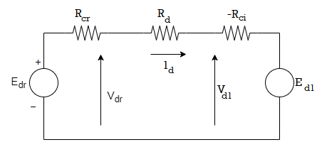
Consider the steady state equivalent circuit of a two terminal DC link. This is based on the assumption that all the series connected bridges in both poles of a converter station are identical and have the same delay angles. Also the number of series connected bridges (nb ) in both stations (rectifier and inverter) are the same.
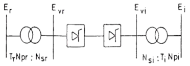
The voltage sources Edr and Edi are defined by
Edr = (3√2/π) nb Evr cosαr ---- (1)
Edi = (3√2/π) nb Evi cosγi ---- (2)
Where Evr and Evi are the line to line voltages in the valve side windings of the rectifier and inverter transformer respectively. From the above figure these voltages can be obtained by

Where Er and Ei are the AC (line to line) voltages of the converter buses on the rectifier and inverter side. Tr and Ti are the OFF-nominal tap ratios on the rectifier and inverter side.

The steady-state current Id in the DC link is obtained as


The control variables in the above equation are Tr, Ti and αr, βi. However, for maintaining safe commutation margin, it is convenient to consider γi as control variable instead of βi.
As the denominator in the final equation is small, even small changes in the voltage magnitude Er or Ei can result in large changes in the DC current, the control variables are held constant. As the voltage changes can be sudden, it is obvious that manual control of converter angles is not feasible. Hence, direct and fast control of current by varying αr or γr in response to a feedback signal is essential. While there is a need to maintain a minimum extinction angle of the inverter to avoid commutation failure, it is economical to operate the inverter at Constant Extinction Angle (CEA) which is slightly above the absolute minimum required for the commutation margin. This results in reduced costs of the inverter stations, reduced converter losses and reactive power consumption. However, the main drawback of CEA control is the negative resistance characteristics of the converter which makes it difficult to operate stably when the AC system is weak (low short-circuit ratios). Constant DC Voltage (CDCV) control or Constant AC Voltage (CACV) control are the alternatives that could be used at the inverter.
Under normal conditions, the rectifier operates at Constant Current (CC) control and the inverter at the CEA control. The power reversal in the link can take place by the reversal of the DC voltage. This is done by increasing the delay angle at the station initially operating as a rectifier, while reducing the delay angle at the station initially operating as the inverter. Thus, it is necessary to provide both CEA and CC controllers at both terminals. The feedback control of power in a DC link is not desirable because
1) At low DC voltages, the current required is excessive to maintain the required level of power. This can be counterproductive because of the excessive requirements of the reactive power, which depresses voltage further.
2) The constant power characteristic contributes to negative damping and degrades dynamic stability.
Q13) List advantages of HVDC transmission?
A13)
(1) A bipolar HVDC overhead line only requires two conductors with positive and negative polarities, thereby providing simple tower structure, low DC-line investment and less power loss. Compared to a double circuit HVAC line with six conductor bundles, one bipolar HVDC line with two conductor bundles takes much less the width of transmission routine. Under the effect of direct voltage, the capacitance of transmission line is never taken into account. Since capacitive current does not exist, direct voltage maintains the same along the transmission line.
(2) For the AC and DC cables with the same insulation thickness and cross section, the transmission capability for DC cable is considerably higher than that for AC cable. DC cable lines only require one cable for monopolar link or two cables for bipolar link and AC cable lines need three cables, due to three phase AC transmission. Therefore, the price for DC cable lines is substantially lower than AC cable lines. Since there is no the cable capacitance in a DC cable transmission, the transmission distance for DC cable is unlimited theoretically.
(3) HVDC links can be used to interconnect asynchronous AC systems and the short circuit current level for each AC system interconnected will not increase. The interconnected AC systems can be operated with different nominal frequencies and the exchange power between interconnected AC systems can be controlled rapidly and accurately.
(4) Due to the rapid and controllable features, HVDC systems can be used to improve the performance of AC system, e.g. The stability of frequency and voltage, the power quality and reliability of interconnected AC systems. For the DC/AC hybrid transmission system, the rapid and controllable features of HVDC system can also be used to dampen the power oscillations in AC systems, so as to increase AC lines transmission capacity.
(5) For an HVDC system, earth can be used as the return path with lower resistance, loss and operational cost. For a bipolar link, earth is normally used as a backup conductor. If faults occur on one pole, the bipolar link can be changed into the monopolar link automatically, thereby improving the reliability of HVDC system. (6) An HVDC transmission system can also be used to link renewable energy sources, such as wind power, when it is located far away from the consumer.
Q14) What are the basis for selection of controls in HVDC transmission?
A14)
The following considerations influence the selection of control
1) Prevention of large fluctuations in direct current due to variations in ac system voltage.
2) Maintaining direct voltage near rated value
3) Maintaining power factors at the sending and receiving end that are as high as possible.
There are several reasons for maintaining the power factor high
(a) To reduce the stresses in the valves.
(b) To minimize losses and current rating of equipment in the ac system to which the converter is connected.
(c) To minimize voltage drops st the ac terminals as loading increases and
(d) To minimize the cost of reactive power supply to the converters.
Rapid control of the converters to prevent large fluctuations in direct current is an important requirement for satisfactory operation of the HVDC link. The line resistance is small. Hence, a small change in Vdr or Vdi causes a large change in Id. It means even 25 % change in voltage at either the rectifier or inverter could cause direct current to change by as much as 100%. This implies that, if both α and γ are kept constant, the direct current can vary over a wide range for small changes in the alternating voltage magnitude at either end. Such variations are not unacceptable for satisfactory performance of the power system. In, addition to this the resulting current may be high enough to damage the valves and other equipment. Therefore, rapid converter control to prevent fluctuations of direct current is essential for proper operation of the system, without such a control the HVDC system would be impractical. For a given power transmitted, the direct voltage profile along the line should be close to the rated value. This minimizes the direct current and thereby the line losses.
Q15) Explain the structure of electrical power system in detail?
A15)
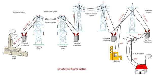
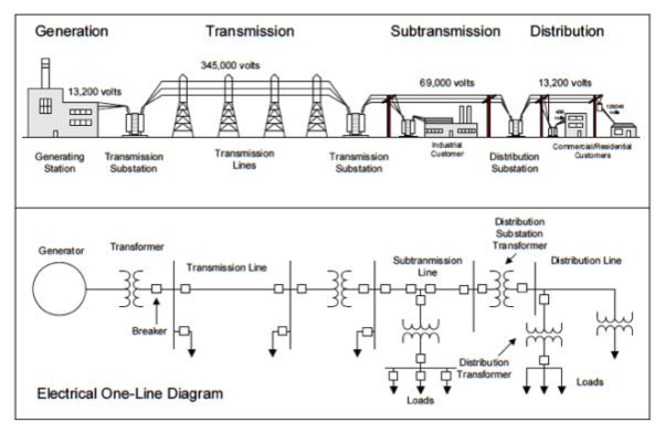
Figure. Power System Structure.
Generating Substation
In generating station the fuel like coal, water, nuclear energy, etc. is converted into electrical energy. The electrical power is generated in the range of 11kV to 25kV, which is step-up for long distance transmission. The power plant of the generating substation is mainly classified into three types, that is thermal power plant, hydropower plant and nuclear power plant.
The generator and the transformer are the main components of the generating station.
Transmission Substation
The transmission substation carries the overhead lines which transfer the generated electrical energy from generation to the distribution substations. It only supplies the large bulk of power to bulk power substations or big consumers.
The transmission lines mainly perform the two functions
- It transports the energy from generating stations to bulk receiving stations.
- It interconnects the two or more generating stations.The neighbouring substations are also interconnected through the transmission lines.
Sub-transmission Substation
The portion of the transmission system that connects the high voltage substations through the step-down transformer to the distribution substations is called the sub-transmission system.
The sub-transmission voltage level ranges from 90 to 138KV. The sub-transmission system directly serves some large industries.
Distribution Substation
The component of an electrical power system connecting all the consumers in an area to the bulk power sources is called a distribution system. The bulk power stations are connected to the generating substations by transmission lines. They feed some substations which are usually situated at convenient points near the load centres.
Q16) Explain the generation transmission and distribution of power devices?
A16)
The power gadget is the complex agency that can be subdivided into the subsequent sub-structures. The subsystems of the power device are explained underneath in details.
Generating substation:
In producing station the gasoline (coal, water, nuclear electricity, and many others.) is transformed into electric electricity. The electrical energy is generated in the variety of 11kv to 25kv, that is step-up for long distance transmission. The power plant of the producing substation is especially classified into three types, i.e., thermal power plant, hydropower plant and nuclear energy plant.
The generator and the transformer are the main components of the producing station. The generator converts the mechanical energy into electrical power. The mechanical electricity comes from the burning of coal, gasoline and nuclear gasoline, gas mills, or sometimes the inner combustion engine.
The transformer transfers the energy with very excessive performance from one level to every other. The energy switch from the secondary is about same to the primary besides for losses within the transformer. The step-up transformer will lessen losses in the line which makes the transmission of electricity over long distances.
Transmission substation:
The transmission substation incorporates the overhead traces which switch the generated electric energy from technology to the distribution substations. It only materials the big bulk of energy to bulk energy substations or very massive customers.
The transmission strains especially perform the 2 functions
- It transports the energy from generating stations to bulk receiving stations.
- It interconnects the 2 or extra producing stations. The neighbouring substations also are interconnected thru the transmission lines.
The transmission voltage is working at greater than 66kv and is standardised at 69kv, 115kv, 138kv, 161kv, 230kv, 345kv, 500kv, and 765kv, line-to-line. The transmission line above 230kv is normally called greater excessive voltage (ehv).
The high voltage line is terminated in substations which can be known as excessive voltage substations, receiving substations or primary substations. In excessive voltage substation, the voltage is step-all the way down to a appropriate cost for the following a part of drift closer to the load. The very huge business customers can be served directly to the transmission system.
Sub-transmission substation:
The portion of the transmission system that connects the excessive voltage substations via the step-down transformer to the distribution substations is referred to as the sub-transmission system.
The sub-transmission voltage degree degrees from 90 to 138kv. The sub-transmission system at once serves a few massive industries. The capacitor and reactor are placed inside the substations for keeping the transmission line voltage.
The operation of the sub-transmission system is similar to that of a distribution system. Its differ from a distribution machine in the following way.
A sub-transmission machine has a higher voltage level than a distribution gadget.
It resources best bigger hundreds.
It resources only some substations compared to a distribution machine which components a few loads.
Distribution substation:
The issue of an electrical power system connecting all of the consumers in an area to the majority energy sources is referred to as a distribution machine.The majority electricity stations are related to the producing substations via transmission strains. They feed a few substations which are typically located at handy points near the load centres.
The substations distribute the energy to the home, business and comparatively small clients. The consumers require huge blocks of energy which might be normally supplied at sub-transmission or maybe transmission gadget.
Q17) Write the advancement in present day scenario of electric technology?
A17)
Electric technology became based at the awesome discovery by faraday that a converting magnetic flux creates an electric powered Field. Out of that discovery, grew the largest and maximum complicated engineering success of guy: the electrical energy device.
Certainly, life without power is now impossible. Electric power systems shape the fundamental infrastructure of a rustic. Even as We examine this, electrical energy is being produced at charges in extra of hundreds of giga-watts (1 gw = one million,000 w).
Large rotors spinning at hastens to 3000 rotations in keeping with minute convey us the energy stored inside the potential energy of water, or In fossil fuels. Yet we note power only whilst the lights go out!
At the same time as the fundamental capabilities of the electrical power machine have remained nearly unchanged inside the beyond century, there are Some good sized milestones inside the evolution of electrical power structures:
First entire dc power machine built by using edison (1882): incandescent lamps supplied by means of steam driven dc turbines (electrical cable machine at 110v). 59 clients unfold over an approximate vicinity with 1.5 km radius.
Improvement of transformers brought about supersession of dc systems by means of ac structures.
Nikola tesla - polyphase induction cars: led to improvement of ac three segment systems.
Interconnection of systems caused standardization of frequency (why?), 60 hz in north the us and 50 hz in most Other international locations. Use of higher and better voltage tiers (up to a thousand kv line-line rms ac). Standardization of voltage Levels.
Development of mercury arc valves, and sooner or later thyristors caused excessive voltage dc transmission (hvdc): dc Transmission appropriate for terribly lengthy distance bulk transmission and underwater cable hyperlinks. First commercial dc link in 1954.
Numerous new trends: gasoline mills, static excitation structures, speedy acting circuit breakers, microprocessor based totally Relaying, use of communique technologies etc.
Want for better utilisation and operation of ac transmission systems by way of use of high electricity electronic converters Advised. Several such converters at the moment are in operation.
Q18) Explain the advantages, need and meaning of smart grid technology?
A18)
A Smart Grid is an electricity Network based on Digital Technology that is used to supply electricity to consumers via Two-Way Digital Communication. This system allows for monitoring, analysis, control and communication within the supply chain to help improve efficiency, reduce the energy consumption and cost and maximise the transparency and reliability of the energy supply chain.
The areas of application of smart grids include: smart meters integration, demand management, smart integration of generated energy, administration of storage and renewable resources, using systems that continuously provide and use data from an energy network.
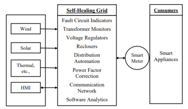
A smart grid automatically detects and responds to routine problems and quickly recovers if they occur, minimising downtime and financial loss. The Self-Healing Grid is a system comprised of sensors, automated controls, and advanced software that utilizes real-time distribution data to detect and isolate faults and to reconfigure the distribution network to minimize the customers impacted. One of the main goals of a Self-Healing Grid is to improve system reliability. This can be accomplished by reconfiguring the switches and reclosers installed on the distribution feeder to quickly isolate the faulted section of the feeder and re-establish service to as many customers as possible from alternate sources/feeders.
A Smart Grid is an electricity network that can intelligently integrate the actions of all users connected to it – generators, consumers and those that do both – in order to efficiently deliver sustainable, economic and secure electricity supplies.
- System (Generation, Transmission, Distribution) with an advanced twoway communications system
- Enables real-time monitoring and control
- Provide greater visibility and transparency
- Consequently, enables cost reduction and efficiency improvement Smart Grid is based on Digital Technology that is used to supply electricity to consumers via Two-Way Digital Communication.
This system allows for monitoring, analysis, control and communication within the supply chain to help improve efficiency, reduce the energy consumption and cost and maximise the transparency and reliability of the energy supply chain. The flow of electricity from utility to consumer becomes a two-way conversation, saving consumers money, energy, delivering more transparency in terms of end-user use, and reducing carbon emissions.
Functions of Smart Grid Components
The areas of application of smart grids include: smart meters integration, demand management, smart integration of generated energy, administration of storage and renewable resources, using systems that continuously provide and use data from an energy network
Smart Devices Interface Component
Smart devices for monitoring and control form part of the generation components real-time information processes. These resources need to be seamlessly integrated in the operation of both centrally distributed and district energy systems.
Storage Component
Due to the variability of renewable energy and the disjoint between peak availability and peak consumption, it is important to find ways to store the generated energy for later use. Options for energy storage technologies include pumped hydro, advance batteries, flow batteries, compressed air, super-conducting magnetic energy storage, super capacitors, and flywheels.
Transmission Subsystem Component
The transmission system that interconnects all major substation and load centers is the backbone of an integrated power system. Transmission lines must tolerate dynamic changes in load and contingency without service disruptions. Efficiency and reliability at an affordable cost continues to be the ultimate aims of transmission planners and operators.
Monitoring and Control Technology Component
Intelligent transmission systems/assets include a smart intelligent network, self monitoring and self-healing, and the adaptability and predictability of generation and demand robust enough to handle congestion, instability, and reliability issues. This new resilient grid has to withstand and be reliable to provide real - time changes in its use.
Intelligent Grid Distribution Subsystem Component
The distribution system is the final stage in the transmission of power to end users. Primary feeders at this voltage level supply small industrial customers and secondary distribution feeders supply residential and commercial customers. At the distribution level, intelligent support schemes will have monitoring capabilities for automation using smart meters, communication links between consumers and utility control, energy management components, and AMI.
Demand Side Management Component
DSM options provide reduced emissions in fuel production, lower costs, and contribute to reliability of generation. These options have an overall impact on the utility load curve. Demand side management options and energy efficiency options developed for effective means of modifying the consumer demand to cut operating expenses from expensive generators and defer capacity addition.
Q19) Explain the components of micro grids?
A19)
A microgrid is a localized group of interconnected loads1 and distributed energy resources (DERs) within clearly defined electrical boundaries (e.g., cities, communities, campuses that act as a single controllable entity with respect to the main regional or national electric grid. A microgrid can connect or disconnect from the main grid as physical and/or economic conditions dictate. It can operate on both grid-connected mode (synchronous with the grid), or on island mode (functioning autonomously and disconnected from the main electric grid). A typical microgrid layout is shown in Figure.
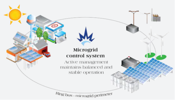
Microgrids, in a more specific sense of the term, refer to grid-connected setups of varying scale that can be “islanded” at will, and established primarily for local reliability, resilience, and operational economics. Islanding is a condition in which distributed generators (DG) continue to provide power in a location even without the continued presence of electrical grid power. This handbook focuses on these islandable microgrids.
The most common objective of a microgrid, especially in the commercial and industrial (C&I) and mission-critical sectors, is to be more reliable and resilient than the utility so that the energy end user continues to have uninterrupted service even during extreme circumstances (e.g., earthquakes, storms, or power grid outages from faults on the utility grid). These “high 9” applications (referring to the level of availability ranging from 99.9% to 99.999%) are usually in hospitals, data centers, military bases, laboratories, etc. In these applications that require a high 9 level of reliability, the microgrid’s cost is viewed as secondary to the purpose, i.e., maintaining energy supply to the facility even under extreme conditions. In situations like these, the value of electricity is often several multiples of its actual cost.
Components of Microgrid
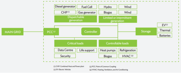
Local Generation
A microgrid must be able to supply energy to its connected loads independent of the utility, so generation sources must exist within the microgrid. These sources could range from readily controlled to intermittent, to not controllable. This could be renewable (e.g., solar PV, wind, biomass; or less frequently used such as solar thermal, hydro, micro-hydro, tidal) or nonrenewable (e.g., diesel, NG, combustion turbines, reciprocating engines, cogeneration, CHP, turbines, microturbines). The selection of energy source needs to be adjusted to the demands on the microgrid, such as the desired generating capacity, required firmness level,8 ramp rate, renewable energy targets, and availability of fuel (and fuel storage requirements). Brownfield microgrid setups often start with some form of existing generation already onsite, such as existing diesel generators, solar panels, or cogeneration facilities.
The existing generation resources influence the additional distributed generation capacity required to be added for supporting the microgrid. Recent decreases in the price solar PV modules and other forms of renewable energy such as wind and biomass, along with energy storage, have enhanced the economic feasibility and attractiveness of renewable energy-based microgrids.
End-Use Loads and Demand-Side
Energy Management The type of end-use devices determines the electrical loads that the microgrid has to be capable of handling, which in turn influences the power-generating capacity and storage requirements. For instance, cell phone charging imposes minimal capacity requirement on the system, but connecting an air conditioner to a solar PV-based microgrid can cause challenges in managing electric loads because of its large continuous power consumption. In reality, a microgrid does not consist solely of one of these extremes, but will have a range of end uses to be served.
Microgrid energy loads range in controllability characteristics from critical loads like data centers or hospital life support equipment at one end of the spectrum, to adjustable controllable loads like air conditioning, lighting, or grid dispatch at the other end. This latter category of loads can be temporarily curtailed or adjusted in line with flexible user requirements, and most modern microgrids will have the capability to control these end uses to optimize the utilization of generation and storage resources.
Demand-response (DR) is defined by Federal Energy Regulatory Commission as “changes in electric usage by end-use customers from their normal consumption patterns in response to changes in the price of electricity over time, or incentive payments designed to induce lower electricity use at times of high wholesale market prices or when system reliability is jeopardized.” DR is a subset of DSM, which includes immediate real-time measures as well as long-term and permanent energy efficiency measures. OpenADR is a standard that supports a range of automated demand-response signals from the utility’s demand-response automation server (DRAS) to automatically control connected equipment in the end-user premises.
Storage
Microgrids must have some form energy storage as a means to time-shift own generation to match load demands, as well as a critical fallback supply in islanded mode operation. With energy storage, the microgrid can absorb and store the energy generated at times when supply exceeds demand, and to subsequently return it at times when demand exceeds supply (e.g., evening peaks once solar PV generation is not available). While there are some inefficiencies from storage and line losses, these are minimal compared to the value that storage can deliver. Energy storage can also be leveraged for arbitrage in wholesale power markets or with time-based rates such as real-time, peak, and ToU pricing. The energy storage technology is chosen based on the size of the microgrid and reaction time required. For instance, for remote microgrids or smaller grid-connected microgrids, batteries are the most commonly used storage technology because the storage capacity required by the microgrid does not justify the higher costs associated with other storage technologies. Batteries can also be used to provide the ancillary services required within a microgrid. Large-scale storage technologies, such hydro-based storage or thermal storage, while cheaper for time shifting operations, have high initial costs that make their implementation in smaller and microgrids challenging.
Microgrid Monitoring and Control System
Microgrid monitoring and control systems (MMCS) tie all of the microgrid components together and maintain the real-time balance of generation and load. This control system can follow a centralized or decentralized scheme. In the most basic of microgrid configurations, the control system might just be a governor controlling a diesel generator. In more complex microgrids, the MMCS comprises sensors, metering, sophisticated software platforms, and communication paths designed to allow for real-time optimization and control of the generators, energy storage, loads, and utility interface. During grid-connected operation, the MMCS needs to manage the utility interconnection and communicate with the system operations center of the utility (or independent system operator), including any DR management systems in near real time.
Utility Interconnection
A distinctive feature of microgrids is the interconnection with the utility’s power grid, sometimes referred to as the PCC. This is what allows microgrids to operate in grid-connected or islanded modes, and transition is relatively seamlessly between both. If there is an existing utility interconnection, it lays the foundation for what additional hardware may be needed for the microgrid. This includes elements ranging from existing relays and meters in the substation and distribution equipment, to switchgears and power converters in the microgrid.
During grid-connected operation, the microgrid-utility interconnection at the PCC must be designed to allow for safe and reliable parallel and concurrent operation of the microgrid and the utility macrogrid. The existing utility equipment may need to be upgraded to handle the various changes that occur when islanding a microgrid. For reliability and resilience, focused microgrids where relatively frequent islanded mode operation is anticipated; the PCC must also incorporate equipment to allow for seamless disconnection and reconnection of the microgrid to the power grid. This re-synchronization of the two systems is a complex process and failure to adequately design for this function can result in instability of both the microgrid and the main power grid. Accordingly, islanding of microgrids must be addressed at both technical and policy levels (safety concerns, potential end user equipment damage, reclosing scenarios, inverter prioritization).
Q20) Compare overhead and underground transmission system?
A20)
Overhead line | Underground Cable |
1) Open to sunlight, storm moist atmosphere, rain, etc.
2) Looks crowded network & spoils the beauty of good localities
3) Cheap in cost
4) Fault detection is easy
5) Maintenance is frequent
6)In case of a fault, joining /replacing is easy
7) Faults detected & repaired in less time & consumers effected for a short time
8) The time required for erections more
9) The line is affected by facing trees
10) In populated areas, there is much more rick & chance of an accident
11) disturbance to telecommunication
| Burned underground and therefore not affected & exposed
Network not seen & beauty of locality not spoiled
Very costly
Fault detection requires a special test
Maintenance is occasional
In case of a fault, joining is tedious & time consuming
Repairs take a lot of time and consumers
Cable laying takes less time
No such chance
Risk is rare
No such chance as the lead sheath is provided |
Q21) What are the feeders in distribution system explain in detail?
A21)
Distribution system is a part of power system, which is between distribution substations the consumer. According to design considerations, the primary distribution system is classified into three types i.e.., radial, loop and network systems.
DESIGN CONSIDERATIONS OF RADIAL TYPE DISTRIBUTION FEEDER
Most distribution systems are designed as radial distribution systems as shown in figure. The radial system is characterized by having only on path between each customer and a substation. The electrical power flows exclusively away the substation and out to the customer along a single path, which, if interrupted results in complete loss of power to the customer. Radial design by far, is the most widely used form of distribution design, accounting for over ninety- nine percent of all distribution in India. Its predominance is due to two overwhelming advantages: its lower cost than the other two alternative and simple in planning, design and operation.
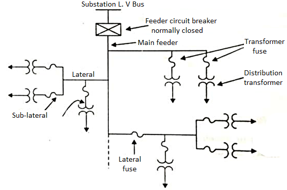
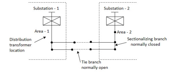
Each radial feeder serves a definite service area. Most radial feeder systems are built as networks, but operated radially by opening switches at certain points throughout the physical network (shown in fig), so that the resulting configuration is electrically radial. The planner determines the layout of the network and the size of each feeder segment in that network and decides where the open points should be for proper operation as a set of radial feeders.
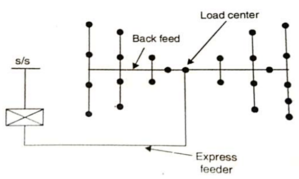
The other type of radial primary feeder with express feeder and back feed is as shown in figure below. The section of the feeder between the substation LV bus and the load center of the service area is called express feeder. From which no sub feeders or laterals will be allowed to be tapped off. The portion from load center towards the substation is called back feed portion. However ,a sub feeder is allowed to provide a back-feed towards the substation from the load center.
Most of the utilities in developed countries are using single and two-phase laterals to deliver power over short distances by tapping off only one or two phases of the primary feeder minimizing the amount of wire that need be strong for the short segment required to get the power in general vicinity of few customers. Each service transformer in these systems feed power into a small radial system around it. Regardless of whether it uses single-phase laterals or not, the advantages of the radial system, in addition to its lower cost, are the simplicity of analysis and predictability for performance.
Because there is only one path between each customer and the substation, the direction of power flow is absolutely certain. Equally important is that the load on any branch of the system can be determined in the most straightforward manner by simply adding up all the customer loads “downstream” from that piece of equipment .Before the advent of economical and widely available computer analysis, this was only an over helming advantage. Simple, straight forward, ”back of the envelope” design procedures can be applied to the distribution system with confidence that the resulting system would work well. The simplicity of analysis and confidence that operating behavior is strictly predictable are major advantages.
Because load and power flow direction are easy to establish, voltage profiles can be determined with accuracy without resorting to exotic calculation methods; equipment capacity requirements can be ascertained at exactly fault levels, can be predicted with a reasonable degree of accuracy; and protective devices, breaker-relays and fuses can be coordinated in an absolutely assured manner, without resorting to network methods of analysis. The major drawback of radial feeder is that it is less reliable than loop or network system because there is only one path between the substation and the customer.
Thus, if any branch along this path fails a loss of power delivery results. Generally, when such failure occurs, a repair crew is dispatched to re-switch temporarily the radial pattern network, transferring the interrupted customers onto another feeder, until the damaged branch can be repaired. This minimizes the period of outages, but an outage still occurred because of the failure.
Q22) Compare feeder and distributors?
A22)
Feeder | Distributor |
In the substance (s), the voltage magnitude is reduced to a utilization level and then the eclectic power is a distribution to the various area through the conductors which is known as feeders. | The distributor is a conductor which distributes the electrical power in particular area. |
A feeder has no tapping on it. | It has a number of tapping on me through which the electrical power is actually reached to consumer premises. |
Current through it always remains same. | The current flowing through it does not remain same. |
While designing a feeder the main consideration is its current carrying capacity. | While designing a distributor the main consideration is a voltage drop and the variation should be within + 6% of rated voltage. |