Unit - 4
Performance of Transmission line
Q1) A 100 km, 50Hz, 3 phase line with r = 0.03ohm, X= 0.10 ohm and C = 0.01  F per km of line length has a load of 2 MW at 0.8 power factor lag at the receiving end. The receiving end is maintained at 11kV by connecting at receiving end a bank of static capacitors rated 1 MVAR at 11kV. Calculate using nominal π-method, the voltage and current at the sending end of the line.
A1)


For a nominal π-network, the generalised ckt. Constants are


Capacitor current,

Receiving end current,

Sending end voltage,


Sending end current,


Q2) A 200 km, 3 phase, 50Hz transmission line has the following data.
A=D =0.938<1.2°, B=131.2<72.3 ohms/phase, C=0.001<90° siemens/phase. The sending end voltage is 230kV. Determine a) the receiving end voltage when the load is disconnected. b) the line charging current
c) the maximum power that can be transmitted at a receiving end voltage of 220kV and the corresponding load reactive power required at the receiving end.
A2)
Sending end phase voltage,

When the load is disconnected,
Ir = 0
Vs = AVr + BIr
192790<0=(0.938<1.2)×Vr + B×0

Vr = 141570<-1.2V
Vrl =  r =
r =  × 141570 = 245200 V
Line charging current,
Ic = C Vr
=0.001<90˚×141570<-1.2=141.57,88.8 A
Maximum power that can be transmitted for Vrl = 220kV and Vs = 230 kV


Corresponding reactive power required at the receiving end,

Q3) A 3 phase transmission line has a resistance per phase of 5 ohm and an inductive reactance of 15 ohm per phase. Determine the load which the line will be supplying at 132kV and 0.8 pf lagging. The sending end voltage is 140kV.
If a synchronous phase modifier is connected in parallel with the load to improve the power factor to 0.95 lagging, determine the leading MVAR supplied by the synchronous phase modifier. Receiving end voltage and load remain unchanged.
A3)
Power factor of the load, 
Load power factor angle, 
For short transmission line, A=1


For receiving end power circle diagram
Radius of circle = 
Coordinates of the centre of the power circle are
Horizontal coordinate = 

Vertical Coordinate =

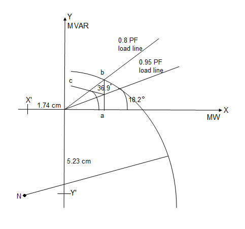
Take scale 1 cm = 200MW horizontally and 1cm = 200MVAR vertically.
Radius of the circle = 1168.8 / 200 = 5.85 cm
Horizontal coordinate = -347.8 / 200 = -1.74 cm
Vertical coordinate = -1045.6 / 200 = -5.23 cm
And draw circle diagram.
From origin 0, draw a line OP inclined at an angle cos-1 0.8 =36.9° with the horizontal cutting the circle at pt. b.
From point b, draw a perpendicular ba on the horizontal axis.
Power supplied at 0.8 pf lagging = Oa = 0.3×200 = 60 MW
Now draw another line OP' inclined at angle cos-1 0.95 = 18.2° with the horizontal cutting the vertical line ba at c.
Total leading MVAR supplied by the synchronous phase modifier
=bc = 0.1 ×200 = 20 MVAR
Q4) A 132 kV, three phase line has the following line parameters.
A=0.98<30°, B=110<75° ohm per phase. If the receiving end voltage is 132kV, determine sending end voltage and power angle if a load 50MVA at 0.8 pf lagging is being delivered at receiving end.
A4)
Given data, VrL = 132 kV A = 0.90<30˚ B=110<75˚ S = 50 mVA
P.F cos =0.8 lagging Vs= ?
Vs = AVr + BIr -----------(1)
Is = CVr + DIr -----------(2)
Sending end voltage (Vs) = AVr + BIr
Vrp = 


Q5) Determine sending end complex power of a transmission line delivering 50mVA at 132kV, 50Hz and 0.8 pf lagging. The ABCD constants of transmission line are A=D=0.9855<0.32, B=67.68<68.6g ohm.
A5)
Given data-
S=50 MVA
VL = 132kV
f = 50 Hz
p.f. = 0.8 lagg
A = D = 0.9855<0.32
B = 67.68 < 68.69 ohm


OR


AD – BC =1


=


Q6) The voltage at Bus A (reference) is 522 kV at an angle of -15 degrees. The voltage at Bus B is 518 kV at an angle of -18 degrees. Total impedance of the transmission path between the buses is 50 ohms. What is (a) the real power flow, and (b) what is its direction?
A6)
(a) PR =  sin
sin = {(522) (518)/50} sin (-150-(-180)) = 283 MW
(b) Direction of flow is from bus A to B
Q7) Calculate the a) real power, and b) it’s direction of flow using the following information: Bus A voltage is 235 kV at an angle of -23 degrees with a power factor of 0.79 Bus B voltage is 237 kV at an angle of -21 degrees with a power factor of 0.85 Total impedance of the transmission path between the buses is 45 ohms
A7)
(a) PR =  sin
sin = {(235) (237)/45} sin (-230-(-210)) = -43.2 MW
(b) Direction of flow is from bus B to A
Q8) Bus A has a voltage of 234 kV at an angle of -18 degrees, and Bus B voltage is 239 kV at an angle of -25 degrees. If the impedance of the transmission path is 45 ohms, what is (a) the reactive power flow between the buses, and (b) in what direction is the reactive power flowing?
A8)
(a) PQ =  cos
cos  = {(239) (239-234)/45} cos {(-250) - (-180)} = 26.4 MVAR
(b) Flow is from Bus B to Bus A
Q9) Calculate the a) reactive power between Bus A and Bus B, and b) it’s direction of flow using the following information: Bus A voltage is 547 kV at an angle of -15 degrees with a power factor of 0.78 Bus B voltage is 544 kV at an angle of -18 degrees with a power factor of 0.81 Total impedance of the transmission path is 86 ohms
A9)
(a) PQ =  cos
cos  = {(547) (547-544)/86} cos {(-150) - (-180)} = 19.07 MVAR
(b) Flow is from Bus A to Bus B
Q10) The single-phase transmission line is now supplying 8 kV to an 800 kVA, 0.9 PF lagging single-phase load. (a) What is the sending end voltage and current of this transmission line? (b) What is the efficiency of the transmission line under these conditions? (c) What is the voltage regulation of the transmission line under these conditions?
A10)
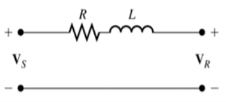
At 50 km length, we can treat this transmission line as a “short” line and ignore the effects of the shunt admittance. The corresponding equivalent circuit is shown below.
The transmission line is supplying a voltage of 8 kV at the load, so the magnitude of the current flowing to the load is
I = S/V = 800kVA/8kV = 100A
(a) If we assume that the voltage at the load is arbitrarily assigned to be at 0° phase, and the power factor of the load is 0.9 lagging, the phasor current flowing to the load is I = 100 ∠-25.8° A . The voltage at the sending end of the transmission line is then
Vs= VR + ZI
Vs= 8000∠0°+(2.1 +j 32.3) (100∠-25.8°)
VS= 10000∠16.4°
(b) The complex output power from the transmission line is
Sout= VR I* = (8000∠0°) ((100∠-25.8°) *= (800000 ∠25.8°) VA
Therefore, the output power is P OUT = 800 cos25.8°= 720 kW
The complex input power to the transmission line is
Sin= Vs I* = (10000∠16.4°) (100∠-25.8°) * = (1000000 ∠25.8°) VA
Therefore the input power is PIN =1000 cos42.2°= 741 kW
The resulting efficiency is
η = [Pout/Pin] x100% = 97.2%
(c) The voltage regulation of the transmission line is
VR = [Vs-VR/VR]x100% = 25%
Q11) The underground cable is now supplying 8 kV to an 800 kVA, 0.9 PF lagging single-phase load. (a) What is the sending end voltage and current of this transmission line? (b) What is the efficiency of the transmission line under these conditions? (c) What is the voltage regulation of the transmission line under these conditions?
A11)
At 50 km length, we can treat this transmission line as a “short” line and ignore the effects of the shunt admittance. (Note, however, that this assumption is not as good as it was for the overhead transmission line. The higher shunt admittance makes its effects harder to ignore.) The transmission line is supplying a voltage of 8 kV at the load, so the magnitude of the current flowing to the load is
I =S/V = 100A
(a) If we assume that the voltage at the load is arbitrarily assigned to be at 0° phase, and the power factor of the load is 0.9 lagging, the phasor current flowing to the load is I = 100 ∠−25.8 ° A. The voltage at the sending end of the transmission line is then
Vs= VR + ZI
Vs= 8000∠0°+(2.1 +j 16.05) (100∠-25.8°)
VS= 8990 ∠8.7°
(b) The complex output power from the transmission line is
Sout= VR I* = (8000∠0°) ((100∠-25.8°) *= (800000 ∠25.8°) VA
Therefore, the output power is P OUT= 800 cos25.8°= 720 kW
The complex input power to the transmission line is
Sin= Vs I* = (8990∠8.7°) (100∠-25.8°) * = (899000 ∠34.5°) VA
Therefore, the input power is PIN= 899 cos34.5°= 740.9 kW
The resulting efficiency is
η = [Pout/Pin] x100% = 97.2%
(c) The voltage regulation of the transmission line is
VR = [Vs-VR/VR]x100% = 12.4 %
Q12) A 138 kV, 200 MVA, 60 Hz, three-phase, power transmission line is 100 km long, and has the following characteristics: r = 0.103 Ω/km x = 0.525 Ω/km y = 3.3 × 10⁻⁶ S/km (a) What is per phase series impedance and shunt admittance of this transmission line?
(b) Should it be modeled as a short, medium, or long transmission line?
(c) Calculate the ABCD constants of this transmission line.
(d) Sketch the phasor diagram of this transmission line when the line is supplying rated voltage and apparent power at a 0.90 power factor lagging.
(e) Calculate the sending end voltage if the line is supplying rated voltage and apparent power at 0.90 PF lagging.
(f) What is the voltage regulation of the transmission line for the conditions in (e)?
(g) What is the efficiency of the transmission line for the conditions in (e)?
A12)
(a) The per-phase series impedance of this transmission line is

The per-phase shunt admittance of this transmission line is

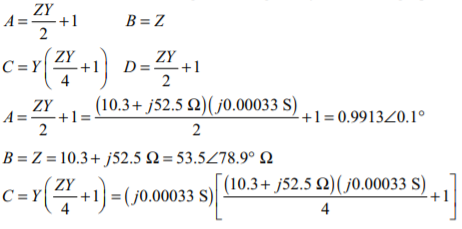
(b) This transmission line should be modeled as a medium length transmission line. (c) The ABCD constants for a medium length line are given by the following equations:

(d) The phasor diagram is shown below:

(e) The rated line voltage is 138 kV, so the rated phase voltage is 138 kV / 3 = 79.67 kV, and the rated current is

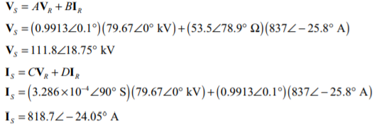
If the phase voltage at the receiving end is assumed to be at a phase angle of 0°, then the phase voltage at the receiving end will be VR = 79.67 ∠ 0 ° kV, and the phase current at the receiving end will be IR = 837 ∠−25.8 ° A. The current and voltage at the sending end of the transmission line are given by the following equations:
(f) The voltage regulation of the transmission line is

(g) The output power from the transmission line is

The input power to the transmission line is

The resulting efficiency is

Q13) A 50 Hz three phase transmission line is 300 km long. It has a total series impedance of 23 + 75j Ω and a shunt admittance of j500 μS. It delivers 150 MW at 220 kV, with a power factor of 0.88 lagging. Find the voltage at the sending end using (a) the short line approximation. (b) The medium-length line approximation. (c) The long line equation. How accurate are the short and medium-length line approximations for this case?
A13)
(a) In the short line approximation, the shunt admittance is ignored. The ABCD constants for this line are:
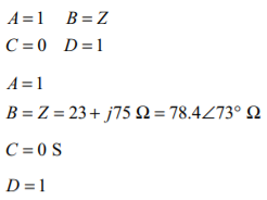
The receiving end line voltage is 220 kV, so the rated phase voltage is 220 kV / √3 = 127 kV, and the current is

If the phase voltage at the receiving end is assumed to be at a phase angle of 0°, then the phase voltage at the receiving end will be VR = 127 ∠0° kV, and the phase current at the receiving end will be IR = 394 ∠−28.4° A. The current and voltage at the sending end of the transmission line are given by the following equations:
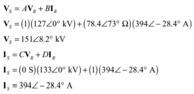
(b) In the medium length line approximation, the shunt admittance divided into two equal pieces at either end of the line. The ABCD constants for this line are:


The receiving end line voltage is 220 kV, so the rated phase voltage is 220 kV / √3 = 127 kV, and the current is

If the phase voltage at the receiving end is assumed to be at a phase angle of 0°, then the phase voltage at the receiving end will be VR = 127 ∠0° kV, and the phase current at the receiving end will be IR = 394 ∠−28.4° A. The current and voltage at the sending end of the transmission line are given by the following equations:
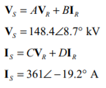
(c) In the long transmission line, the ABCD constants are based on modified impedances and admittances:
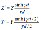
And the corresponding ABCD constants are

The propagation constant of this transmission line is


The modified parameters are

And the ABCD constants are
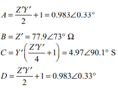
The receiving end line voltage is 220 kV, so the rated phase voltage is 220 kV / √3 = 127 kV, and the current is

If the phase voltage at the receiving end is assumed to be at a phase angle of 0°, then the phase voltage at the receiving end will be VR = 127 ∠0° kV, and the phase current at the receiving end will be IR = 394 ∠−28.4° A. The current and voltage at the sending end of the transmission line are given by the following equations:
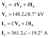
The short transmission line approximate was rather inaccurate, but the medium and long line models were both in good agreement with each other
Q14) A 60 Hz, three phase, 110 kV transmission line has a length of 100 miles and a series impedance of 0.20 + j0.85 Ω/mile and a shunt admittance of 6x10⁻⁶ × S/mile. The transmission line is supplying 60 MW at a power factor of 0.85 lagging, and the receiving end voltage is 110 kV. (a) What is the voltage, current, and power factor at the receiving end of this line? (b) What is the voltage, current, and power factor at the sending end of this line? (c) How much power is being lost in this transmission line? (d) What is the current angle δ of this transmission line? How close is the transmission line to its steady-state stability limit?
A14)
This transmission line may be considered to be a medium-line line. The impedance Z and admittance Y of this line are:

The ABCD constants for this line are:


(a) Assuming that the receiving end voltage is at 0°, the receiving end phase voltage and current are.
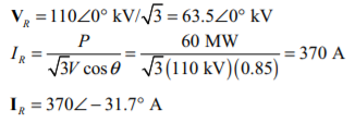
The receiving end power factor is 0.85 lagging. The receiving end line voltage and current are 110 kV and 370 A, respectively.
(b) The sending end voltage and current are given by

The sending end power factor is cos [15.35- (-26)] =cos 41.4= 0.751 lagging
The sending end line voltage and current are √3 (87.8 kV) =152 kV and 342 A, respectively.
(c) The power at the sending end of the transmission line is

The power at the receiving end of the transmission line is

Therefore, the losses in the transmission line are approximately 7.8 MW.
(d) The angle δ is 15.35°. It is about 1/4 of the way to the line’s static stability limit.
Q15) Explain classification of transmission lines?
A15)
The category of the transmission traces depends on its voltage and the length of the conductor. The transmission line is the medium of transferring the power from the generating station to the burden center.
It is mainly classified into two types. They're the
1) AC transmission line
- Short-transmission line
- Medium transmission line
- Pi model of a medium transmission line
- T model of a medium transmission line
- Long transmission line
2)Dc transmission line
1. Ac transmission line
The transmission line has resistance r, inductance l, capacitance c and the shunt or leakage conductance g. Those parameters at the side of the weight and the transmission line decide the performance of the road.
The time period overall performance approach the sending stop voltage, sending cease currents, sending cease energy aspect, energy loss within the line, efficiency of the transmission line, adjust and restrict of electricity float during performance and transmission, law and boundaries of power at some stage in steady nation and short circumstance.
The contrast chart of the transmission line is proven inside the determine below.
Type-of-transmission-line
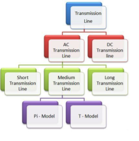
Short transmission line
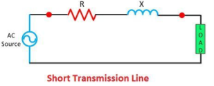
If the line isn't always greater than 80 kv or if the voltage isn't over than sixty-six kv then the road is called the short transmission line. The capacitance of the line is ruled via their period. The impact of capacitance on the short transmission line is negligible, however for cable in which the gap among the conductor is small, the effect of capacitance can't be neglected. At the same time as reading the performance of the fast transmission line only resistance and the inductance of the line is calculated.
Medium transmission line
The road that is starting from eighty to 240 km is termed as a medium transmission line. The capacitance of the medium transmission line can't be neglected. The capacitance of the medium transmission line is considered to be lumped at one or greater factor of the traces. The impact of the line is greater at excessive frequency, and their leakages inductance and capacitance is taken into consideration to be disregarded. The medium transmission line is sub-divided into pi – model and t – model.
Pi model of a medium transmission line
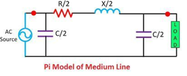
In nominal pi model, it is assumed that the 1/2 of the capacitance pay attention on the every end of the road.
T – model of a medium transmission line

In t model, it is assumed that the capacitance is focused at the center of the road.
Medium-transmission-line-pi-model
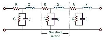
Long transmission line
The road having a duration extra than 240 km is considered a long transmission line. All the 4 parameters (resistance, inductance, capacitance, and leakage conductance) are observed to be equally dispensed alongside the whole period of the road.
2. Dc transmission line
The dc transmission is in particular used for the bulk energy transmission. For long distance transmission, the dc is less luxurious and feature low electrical losses. The fee of the dc transmission structures is better for short distance transmission line as it requires more convertible equipment as compared to an ac device.

The converter station converts the ac to dc on the sending cease and dc to ac at the load quit of the road. One of the main gain of the dc machine is that it allows the power transmission among two unsynchronized ac system.
Q16) Explain voltage regulation and efficiency of transmission line?
A16)
Manage of voltage profile of transmission line on the receiving bus in the essential two-bus device changed into discussed already. Though the identical preferred conclusions preserve for an interconnected device, it's miles essential to talk about this problem in extra element.
At a bus with technology, voltage can be simply controlled by using adjusting generator excitation. That is illustrated with the aid of fig. wherein the equivalent generator on the it bus is modeled by using a synchronous reactance (resistance is assumed negligible) and voltage in the back of synchronous reactance.
It right away follows upon application of eqs.
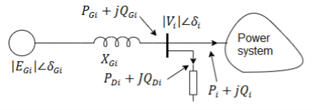


Vi the load flow solution, these values can be carried out on the bus via adjusting generator excitation to breakthrough eq. And by way of adjusting the governor setting in order that power input to generator from turbine is pgi plus losses, ensuing in load angle of (δgi – δi) corresponding to eq.
If Egi demand exceeds the capacity of generators, var generators (synchronous or static capacitor) ought to be used to adjust the nearby load.
If follows from above that to control the voltage profile of transmission line of an inter-connected gadget, buses with turbines are usually made pv (i.e. Voltage manage) buses. Load glide solution then gives the voltage levels on the load buses.
If a number of the weight bus voltages workout to be much less than the specified lower voltage restricts, it is indicative of the fact that the reactive power waft potential of transmission strains for exact voltage limits cannot meet the reactive load call for (reactive line waft from bus i to bus okvk. This example can be remedied via putting in var generators at a number of the weight buses.
These buses within the load glide analysis are then regarded as pv buses with the ensuing solution giving the requisite values of var (jqc) injection at those buses.
The truth that wonderful var injection at any bus of an interconnected device could help to raise the voltage at the bus is effortlessly established below: discern 6.15a suggests the Thevenin equal circuit of the electricity machine as visible from the it bus. Obviously, eth = vi. If now jqc from var generator is injected into this bus as proven in fig. b, we've from eq.


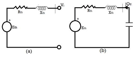
Due to the fact we're considering a voltage upward push of some percent may be further approximated as

Calculation and analysis of performance of transmission lines
There are 3 most important type of overhead transmission lines:
Short transmission line – the road period is as much as 60 km and the line voltage is comparatively low less than 20kv.
Medium transmission line – the road period is between 60 km to 160 km and the road voltage is between 20kv to 100kv.
Long transmission line – the line duration is greater than 160 km and the line voltage is excessive more than 100kv.
Anything may be the class of transmission line, the primary purpose is to transmit strength from one give up to every other.

Power sent from sending end – line losses = Power delivered at receiving end
Like different electrical machine, the transmission community additionally could have a few energy loss and voltage drop for the duration of transmitting energy from sending quit to receiving give up. Subsequently, performance of transmission line may be decided by means of its performance and voltage regulation.
Voltage law of transmission line is measure of change of receiving stop voltage from no-load to full load circumstance.
Transmission line
Every transmission line may have 3 basic electric parameters. The conductors of the road can have electrical resistance, inductance, and capacitance. As the transmission line is a set of conductors being run from one vicinity to another supported by using transmission towers, the parameters are dispensed uniformly alongside the line.
The electrical power is transmitted over a transmission line with a pace of mild that is three × 108 m ⁄ sec. Frequency of the electricity is 50 Hz. The wave length of the voltage and cutting-edge of the strength may be determined by the equation given under,
Therefore,


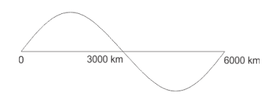
Voltage distribution of 50hz supply
F.λ = v in which, f is electricity frequency, λ is wave length and υ is the speed of mild.
As a result, the wave length of the transmitting energy is quite lengthy compared to the commonly used line duration of transmission line.
Because of this, the transmission line, with period less than 160 km, the parameters are assumed to be lumped and now not allotted. Such strains are known as electrically short transmission line. This electrically quick transmission traces are once more categorized as short transmission line (period as much as 60 km) and medium transmission line (duration between 60 and a hundred and sixty km).
The capacitive parameter of brief transmission line is neglected whereas in case of medium length line the, capacitance is thought to be lumped on the middle of the line or 1/2 of the capacitance can be considered to be lumped at every ends of the transmission line. Traces with duration greater than 160 km, the parameters are considered to be disbursed over the line. This is referred to as long transmission line.
Q17) What is Ferranti effect explain in detail?
A17)
The Ferranti effect is a phenomenon that describes the boom in voltage that occurs at the receiving give up of a long transmission line relative to the voltage at the sending give up. The Ferranti effect is extra everyday while the weight could be very small, or no load is hooked up (i.e., An open circuit). The Ferranti impact can be stated as a factor, or as a percent boom.
In standard practice we know, that for all electrical structures present day flows from the region of better ability to the location of decrease potential, to atone for the electric potential difference that exists within the device. In all practical instances, the sending give up voltage is better than the receiving cease because of line losses, so modern-day flows from the source or the deliver quit to the burden.
But sir S.Z. Ferranti, in the yr. 1890, came up with a dazzling concept about medium transmission line or long-distance transmission strains suggesting that during case of light loading or no-load operation of the transmission system, the receiving quit voltage frequently will increase beyond the sending end voltage, main to a phenomenon called Ferranti impact in a power device.
Ferranti effect in transmission line
An extended transmission line can be taken into consideration to compose a notably excessive amount of capacitance and inductance allotted throughout the complete length of the road. Ferranti effect happens whilst present day drawn by means of the disbursed capacitance of the line itself is extra than the contemporary associated with the weight at the receiving stop of the road (for the duration of light or no load).
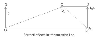
This capacitor charging modern ends in a voltage drop throughout the line inductor of the transmission device that's in section with the sending cease voltages. This voltage drop continues on growing additively as we move toward the weight quit of the road and sooner or later, the receiving end voltage tends to get larger than implemented voltage leading to the phenomena referred to as Ferranti impact in strength machine. We illustrate that with the help of a phasor diagram beneath.
As a consequence, each the capacitance and inductor effect of transmission line are similarly liable for this unique phenomenon to arise, and subsequently Ferranti effect is negligible in case of a short transmission line because the inductor of this kind of line is almost considered to be nearing zero.
In popular for a 300 km line operating at a frequency of fifty Hz, the no-load receiving quit voltage has been observed to be 5% better than the sending stop voltage.
Now for the evaluation of the Ferranti impact let us take into account the phasor diagrams shown above.
Right here, vr is considered to be the reference phasor, represented by OA.
Thus 
Capacitance current 
Now sending end voltage 


Now 
This is represented with the aid of the phasor oc.
Now in case of a “long transmission line,” it's been practically found that the road electric resistance is negligibly small compared to the line reactance. Therefore, we can assume the period of the phasor ic r = zero; we can do not forget the upward thrust inside the voltage is best due to oa – oc = reactive drop inside the line.
Now if we bear in mind c0 and l0 are the values of capacitance and inductor according to km of the transmission line, wherein l is the period of the road.
Thus capacitive reactance

On account that, in case of an extended transmission line, the capacitance is shipped during its duration, the average current flowing is,

Now the inductive reactance of the line 
Accordingly, the rise in voltage due to line inductor is given via,

Voltage rise 
From the above equation it's miles clearly obvious, that the upward push in voltage on the receiving give up is at once proportional to the rectangular of the line duration, and consequently in case of an extended transmission line it keeps increasing with length, or even is going past the applied sending stop voltage at times, leading to the phenomena called Ferranti effect.
Q18) Write short notes on surge impedance loading?
A18)
Surge impedance loading is a very critical parameter on the subject of the study of strength structures as it's far used inside the prediction of maximum loading capability of transmission strains.
However earlier than knowledge SIL, we first want to have a concept of what's surge impedance (zs). It could be described in two methods one an easier one and other a bit rigorous.
Approach 1
It's miles a well-known truth that an extended transmission strains (> 250 km) have disbursed inductance and capacitance as its inherent property. Whilst the road is charged, the capacitance component feeds reactive power to the line whilst the inductance factor absorbs the reactive electricity. Now if we take the balance of the two reactive powers we arrive at the subsequent equation
Capacitive var = inductive var

In which,
V = section voltage
I = line modern
Xc = capacitive reactance in keeping with section
Xl = inductive reactance in line with section
Upon simplifying

In which,
F = frequency of the gadget
L = inductance consistent with unit duration of the line
L = length of the road
For this reason, we get,

This quantity having the dimensions of resistance is the surge impedance. It could be taken into consideration as a simply resistive load which whilst related at the receiving stop of the line, the reactive electricity generated by using capacitive reactance will be absolutely absorbed by means of inductive reactance of the road.
It's far not anything however the function impedance (zc) of a lossless line.
Technique 2
From the rigorous answer of a long transmission line, we get the subsequent equation for voltage and modern-day at any point on the line at a distance x from the receiving end


In which,
Vx and ix = voltage and cutting-edge at point x
Vr and ir = voltage and contemporary at receiving stop
Zc = function impedance
δ = propagation constant


Z = series impedance in step with unit length in line with segment
Y = shunt admittance in step with unit period in line with phase
Setting the cost of δ in above equation of voltage we get

Wherein,


We look at that the immediately voltage includes phrases each of that's a characteristic of time and distance. As a result, they constitute travelling waves. The primary one is the nice exponential component representing a wave travelling in the direction of receiving give up and is for this reason called the incident wave. At the same time as the other component with negative exponential represents the reflected wave. At any factor along the line, the voltage is the sum of each the waves. The same is true for modern-day waves additionally.
Now, if assume the weight impedance (zl) is selected such that zl = zc, and we recognize

As a result

And hence the meditated wave vanishes. This type of line is called as infinite line. It seems to the supply that the road has no stop as it receives no pondered wave.
As a result, such an impedance which renders the road as limitless line is referred to as surge impedance. It has a price of approximately 400 ohms and segment perspective varying from zero to –15 diploma for overhead traces and around forty ohms for underground cables.
The term surge impedance is however used in connection with surges on the transmission line which may be due to lightning or switching, where the line losses may be unnoticed such that

Now that we have understood surge impedance, we can without difficulty define surge impedance loading.
Sil is defined as the power introduced through a line to a basically resistive load same in value to the surge impedance of that line. Hence, we will write

The unit of SIL is watt or mw.
Whilst the line is terminated with the aid of surge impedance the receiving end voltage is identical to the sending stop voltage and this example is known as flat voltage profile. The subsequent discern shows the voltage profile for extraordinary loading cases.
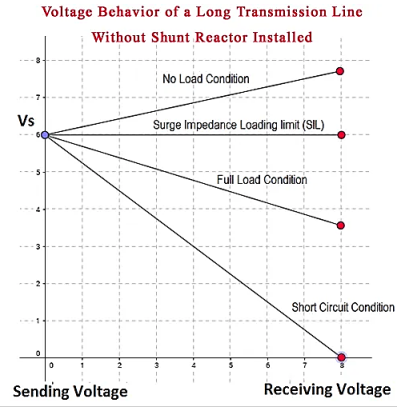
It needs to additionally be cited that surge impedance and consequently SIL is impartial of the length of the road. The fee of surge impedance may be the same at all of the points on the line and hence the voltage.
In case of a compensated line, the value of surge impedance can be modified hence as

Where, kse = % of series capacitive compensation with the aid of Cse

Kcsh = % of shunt capacitive compensation by csh

Klsh = % of shunt inductive compensation by lsh

The equation for sil will now use the modified zs.
Q19) What is series and shunt compensation of transmission line. Explain in detail?
A19)
In series compensation, the information is attached in series with the energy machine. It really works as a controllable voltage supply. Series inductance occurs in long transmission lines, and when a big cutting-edge flows this causes a huge voltage drop. To compensate, series capacitors are connected, decreasing the effect of the inductance.
Shunt compensation
In shunt compensation, electricity device is hooked up in shunt (parallel) with the facts. It really works as a controllable modern-day source. Shunt compensation is of kinds:
Shunt capacitive compensation
This technique is used to enhance the electricity element. On every occasion an inductive load is connected to the transmission line, power aspect lags because of lagging load contemporary. To compensate, a shunt capacitor is hooked up which attracts modern-day leading the supply voltage. The net end result is development in strength issue.
Shunt inductive compensation
This technique is used either while charging the transmission line, or, while there may be very low load at the receiving quit. Because of very low, or no load – very low current flows via the transmission line. Shunt capacitance within the transmission line causes voltage amplification (Ferranti impact). The receiving quit voltage may also come to be double the sending stop voltage (usually in case of very long transmission strains). To compensate, shunt inductors are connected throughout the transmission line.
Concept
In the case of a no-loss line, voltage significance at receiving quit is the same as voltage magnitude at sending stop: vs = vr=v. Transmission outcomes in a segment lag î´ that relies upon online reactance x.
As it is a no-loss line, lively energy p is the same at any factor of the road:
Reactive power at sending quit is the other of reactive electricity at receiving cease:
As î´ may be very small, energetic strength specifically depends on î´ while reactive strength especially relies upon on voltage magnitude.
Series compensation
Records for series compensation modify line impedance: x is reduced that allows you to growth the transmittable energetic electricity. But, extra reactive strength ought to be supplied.
Shunt compensation
Reactive present day is injected into the line to keep voltage value. Transmittable active electricity is elevated but greater reactive strength is to be supplied.
Examples of series compensation
Examples of records for series compensation (schematic)
Static synchronous series compensator (sssc)
Thyristor-controlled series capacitor (tcsc): a series capacitor bank is shunted by way of a thyristor-controlled reactor
Thyristor-controlled series reactor (tcsr): a series reactor bank is shunted by way of a thyristor-controlled reactor
Thyristor-switched series capacitor (tssc): a series capacitor bank is shunted by way of a thyristor-switched reactor
Thyristor-switched series reactor (tssr): a chain reactor bank is shunted with the aid of a thyristor-switched reactor
Transmission line series capacitor compensator after the country of the gadget had greater in-depth research, talked about that a few machine problems, inclusive of over-voltage level upward thrust, arc modern-day increases and the possibility of sub-synchronous resonance series capacitor compensator are derived from the inherent traits, via the have a look at concluded that after the series compensated transmission line wherein an inner failure, which includes the imposition of protecting measures is induced skip gap was to avoid immoderate stages of the device recuperation voltage and arc contemporary troubles which include an effective way to boom. In addition, proposed the installation of series compensation stations to reveal sub-synchronous resonance suppressed or secondary tool to suppress and save you system at sub synchronous resonance.
Use of series capacitor compensation method can improve lengthy-distance transmission strains ehv transmission ability and system stability, and the fashion of the transmission channel on the distribution of a certain regulatory role. Tcsc can inhibit use of the machine low frequency oscillation and optimized systems to the fashion of distribution; but, the increase within the device changes the series capacitor compensation equipment, electric system, the space between the original, particularly the high diploma of series compensation, it could cause a chain of machine issues, and therefore pay for the undertaking string of per-examine stage ought to any such opportunity careful have a look at and advise answers to troubles of the corresponding packages and measures.
China southern electricity grid is based totally on guizhou, yunnan and tianshengqiao energy grid for the sending side, via the tianshengqiao to Guangdong’s 3 again to 500kv ac transmission line and a go back to 500kv dc transmission line and by the cease of the Guangdong electricity grid linked to the trans-provincial (nearby) energy grids, 2003 June guizhou – Guangdong’s double-circuit 500kv ac transmission traces built and positioned into operation, china southern energy grid to shape a transport-side ‘pay has been 5’, with the aid of the stop of ‘4 go has been’ within the northern, valuable, south 3 west to east a prime thoroughfare.
As the size of china southern energy grid to in addition make bigger west to east so one can enhance the shipping of these transmission channel potential and the level of protection and balance of the whole network and suppression system, low-frequency oscillation, it changed into decided that at pingguo hechi substation with the installation of controllable series compensation (tcsc) and stuck-series compensation (fsc).
Through the China southern electricity grid pingguo tcsc works and hechi fsc systematic research at the works, the writer of the ehv long-distance transmission system, using series capacitor compensation technique can be due to system problems obtained a more comprehensive information of and summarizes the measures to solve those troubles and packages
Series compensation is a properly mounted era that mainly is used to lessen switch reactance’s, maximum considerably in bulk transmission corridors. The end result is a significant boom within the transmission gadget temporary and voltage balance.
Series compensation is self-regulating inside the experience that its reactive electricity output follows the versions in transmission line modern, a truth that makes the series compensation idea extremely sincere and fee powerful.
Thyristor controlled series capacitors adds another controllability size, as thyristors are used to dynamically modulate the ohms furnished by the inserted capacitor. This is in general used to provide inter-location damping of prospective low frequency electromechanical oscillations, but it additionally makes the whole series compensation scheme resistant to sub synchronous resonance (stir).
Constant series compensation is considering long the desired answer whilst large bulk transmission corridors will be optimized. Putting a capacitive reactance in series with a protracted (generally extra than 200km) transmission line, reduces each the angular deviation and the voltage drop, resulting in improved load ability and balance.
The fact that it is the cutting-edge thru the transmission line that at once “drives” the mvar output from the capacitor, makes the compensation concept “self-regulating”, and this straightforward principle assures that series compensation is an exceedingly cost powerful solution. It offers:
– expanded brief (angular) balance of an energy corridor
– accelerated voltage stability of the grid
– advanced voltage profile along the electricity corridor
– optimized energy sharing among parallel circuits
Series capacitor installations are established in series with a transmission line, which means that that everyone the device must be hooked up on a platform this is absolutely insulated for the gadget voltage in question. On this metallic platform, the main capacitor is positioned collectively with the overvoltage protection circuits.
The overvoltage protection is a key design element as the capacitor financial institution has to withstand the throughput fault modern-day, even at an excessive nearby fault. The primary overvoltage protection generally entails non-linear metal-oxide varistors, a spark hole and a quick pass transfer. Secondary safety is achieved with ground set up electronics appearing on indicators from optical cutting-edge transducers in the excessive voltage circuit.