Unit - 2
Effect of feedback on parameter variations
Q1) Differentiate between AC and DC Tachometer?
A2)
| D.C. Tachometer | A.C. Tachometer |
1. | They convert rotational speed into a proportional dc voltage. | They convert the rotational speed into a proportional ac voltage. |
2. | It uses a permanent magnet for producing magnetic field. It contains iron core rotor. | It works on principle of induction generator. |
3. | The permanent magnet controls the magnetic field therefore the induce voltage at terminal of armature is proportional to shaft speed. | The reference winding is supplied by reference voltage and the output voltage is induced across the output winding. |
4. | The polarity depends on direction of rotation. | The amplitude and phase depends on the direction of rotation. |
Q2) Explain how we could get control over the system dynamics by use of feedback?
A2)
The dynamics of the system can be controlled by the feedback by adjusting the location of poles. In this section we will see how the location of poles effect the dynamics of the system.
Let us consider a system which has open loop transfer function of G(s) defined as
G(s) =  (1)
(1)
Let K =  /
/
 = 1/
= 1/
The poles for the above system lie at s= - and
and  =1/
=1/ is time constant.
The dc gain of the system is given by G(0) = K =  /
/
For closed loop system the transfer function is given by
 (2)
(2)
 =
= 
 =
=  /(1+K)
The above equation shows that due to feedback the system pole shifts from - to (–
to (– +K’). Due to this change the dynamic response of the system is also affected. For studying the dynamic response, we assume that the input to the system is an impulse.
r(t) =  (t)
(t)
And it can also be written as
R(s) = 1
Taking inverse Laplace transform of equation 1 we get
For open loop system
c(t) = K’
Taking inverse Laplace transform of equation 2 we get
For closed loop system
c(t) = K’
The system dynamic response decays in both the open system as well as closed loop system. The closed loop system time constant is  =
=  /(1+K) so its response decays faster than open loop system by factor of (1+K).
Q3) Explain Ziegler Nichols method for tuning of controllers?
A3) They proposed the rules for determining values of proportional gain kp, derivative time Td and integral time Ti. They have proposed from (1) methods.
1) First Method: The basic PID controller is shown in figure below. In this method a unit step response of a plant. Is obtained if the plant has neither integrator non dominant complex conjugal poles, then the output step curve is of shape s. As shown below. These curves are generated experimentally.
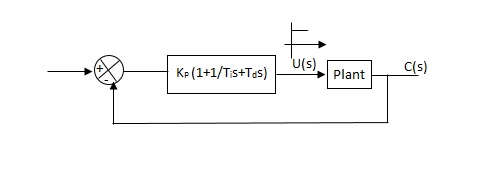
Fig 1. PID CONTROLLER
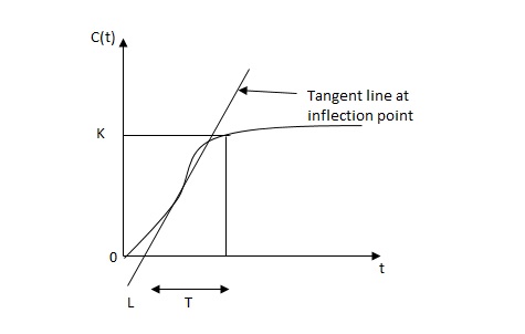
FIG 2. S-SHAPED RESPONSE CURVE

c(s) / l(s) = ke-l1s / ts+1
The values of KP, Ti and td should be set according to the table suggested by Ziegler Nichols tuning rules shown below.
Type of controller
Types of controller | Kp | Ti | Td |
P | T/L | 00 | 0 |
PI | 0.9T/L | L/0.3 | 0 |
PID | 1.2T/L | 2L | 0.5L |
Controller gain Gc(s)= kp(1+1/Tis+Tds)
= 1.2T / L(1+1 / 2LS+0.5 LS)
= 1.2t/l+0.6t / L2S+0.6TS
= 0.6T(2/L+1/L2S+S)
Gc(s) = 0.6 T(S+1/L)2/S
Thus, the PID controller has a pole at the origin and double zeros at S=-1/ L
2) Second Method
1) Firstly, set Ti= and Td=0
2) Use proportional control action only, increase kp from 0 to Kcr (Critical value).
3)Then Kcr and pcr (period) are determined experimentally.

Fig 3 closed loop with proportional controller
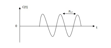
Fig 4 sustained oscillation with period pcr.
4)For this method Ziegler Nichols suggested new set of values for kp ,ti and td shown in table below.
Types of controller | KP | TI | Td |
P | 0.5Kcr |  | 0 |
PI | 0.45 KCR | 1/1.2PCR | 0 |
PID | 0.6KCR | 0.5PCR | 0.125PCR |
|
|
|
|
GC(S) = KP(1.1/Tis+Tds)
=0.6 Kcr(1+1/0.5PcrS+ 0.125 PCRS)
=0.075 KcrPcr(s+4/Pcr)2 / s
Thus, the PID controller has a pole at the origin and double zeros at s= -4/Pcr
Q4) What is effect of feedback on parameter variations?
A4)
The feedback systems are having many advantages over the non-feedback system as we have seen earlier. So, some performance parameters can be controlled through this feedback system such as sensitivity, noise etc. Sensitivity is a parameter which forecasts the effectiveness of feedback in reducing the influence of these variations on system performance.
The output of the open loop system is given by
C(s) = G(s)R(s)
Now due to variation in parameters G(s) changes to [G(s)+G(s)]. The output will now become
C(s)+ C(s) = [G(s)+ G(s)] R(s)
C(s) = G(s)R(s)
For closed loop system the output is given as

Now due to variation in parameters it becomes

The above equation shows that if there is variation in parameters then G(s) is reduced by factor of 1+G(s)H(s). The variation in overall transfer function T(s) due to change in G(s) is defined as sensitivity.

When there is small change in G(s) then sensitivity becomes

 : Sensitivity of T w.r.t G
For closed loop system the sensitivity will be

For open loop system

As T=G
The sensitivity of T w.r.t H is given as

The above equation shows that for large values of GH sensitivity of the feedback system w.r.t H approaches to unity.
Q5) Explain how feedback signal helps to control the disturbance signal in control system?
A5)
The feedback helps to control the disturbances as they generate an error signal. The signal flow graph for closed loop system is given by
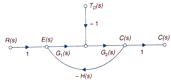
Fig 5. Closed loop system with disturbance signal
 =
= 
Where:
TD(s) = Disturbance signal.
For |G1G2H(s)|>>1 over the range of s
 =
=
The signal flow graph of a system with noise signal N(s) in the feedback path. The gain is given by
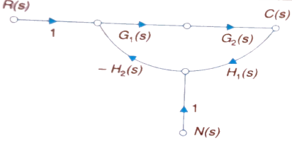
Fig 6. SFG for noise feedback function
 =
= 
For  >>1
>>1
Cn(s) = 
The feedback reduces sensitivity, improves transient response and minimises the effects of disturbance signal in control system.
Q6) What are the components of control system explain? Taking an example explain the state equation of any electrical network?
A6)
A closed loop control system consists of three basic elements: the feedback element, controller and controlled system. The controller consists of error detector and control elements.

The control element manipulates the actuating signal preferably to different power stage so as to fed to the controlled system. The power stage in control elements is essential for the control signal to drive controlled system. Control elements plays a vital role to get the desired output.
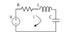
Electrical System
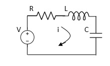
Applying Kirchoff’s voltage Law
V= Ri +Ldi/dt +1/cidt
V= Rdq/dt + L d2q/dt2+q/c
Now By kirchoff’s current low
I= V/R+ 1/L vdt+ cdv/dt
But V= dø/dt
I= 1/R dø/dt + 1/L ø+cd2ø/dt2
But v= dø/dt
I= 1/R dø/dt+ 1/L. ø+c d2ø/dt2
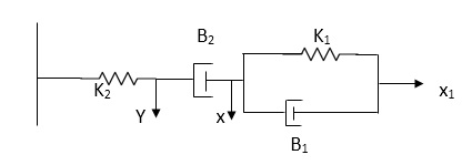
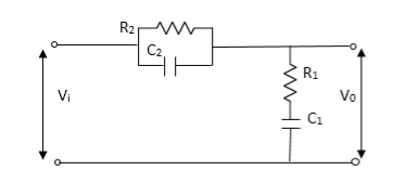
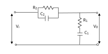
Q7) For the given mechanical system below draw the analogous system (force. Voltage) & find V0(s)/V1(s)
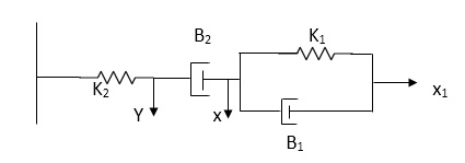
A7)
Form the table above we can find the analogus values of system components.
(1) Consider two displacement as two nodes.
(2) If masses are present connect them to reference lines
(3) Connect other elements of system to the nodes
(4) Applying modal analysis to find the system equation.
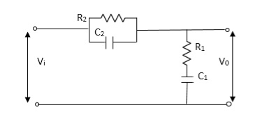
Let Z1 = R2 11 1/c2
=R2*1/c2s/R2+1/c2s
Z1= R2/1+R2c2s
Let Z2 = R1+1/c1s
Z2= 1+R1c1s/c1s
V0(s)/vi(s) = z2/z1+z2
= 1+R1c1s/c1s/R2/1+R2c2s+1+R1c1s/c1s
V0(s)/v0(s) =(c1+R1c1s) (1+R2c2s)/R2c1s+1+sR1c1s2R1R2c1c2
Q8) What are magnetic amplifiers, explain its working and types?
A8)
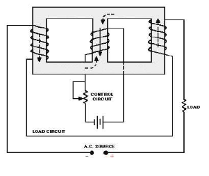
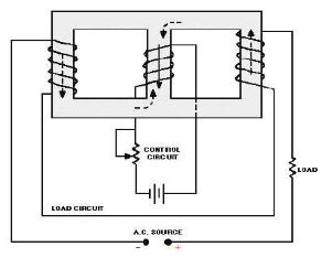
They are basically electromagnetic device used for amplification of electrical signals. The basic working of this amplifier depends on the saturation of core principle. It consists of two cores connected in opposite phases, with control and AC winding. By applying small amount of DC currents on control winding large amount of current on AC winding can be controlled. They are of two types
a) Half wave magnetic amplifier: When DC supply is given to the control winding the magnetic flux is generated in the iron core. As flux increases the output impedance decreases and the current through AC winding in output increases. Here only half cycle of AC is utilised.
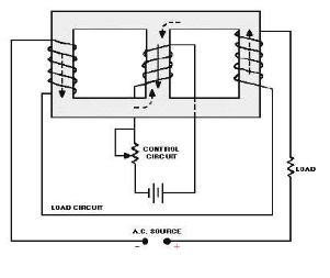
If the current through the control winding is zero, then the impedance of the output winding will be very high making no current to flow through the load or output winding. A diode is connected to the output winding which acts as a rectifier, used for reversing the polarity of the AC supply constantly from cancelling out control winding flux.
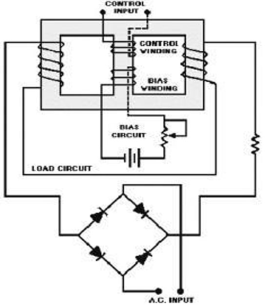
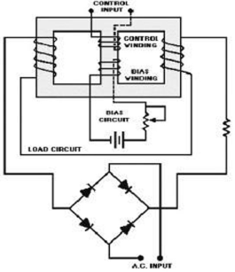
b) Full wave magnetic amplifier: It utilizes both the half cycles of the AC supply. Due to wound of the two halves of the output winding the direction of magnetic flux created by these two halves in centre leg is same as direction of control winding flux
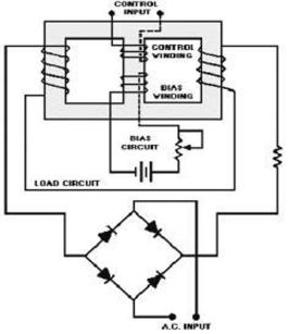
No control voltage is supplied there will be some flux present in magnetic core, hence impedance of the output winding will never attain its maximum value and current through load never attain its minimum value. The operation of the amplifier can be controlled by using the bias winding.
Q9) Explain servomechanism and ac servomotor with torque speed characteristics?
A9)
Servomechanism is also called servo which is a device usually error sensing device connected as a feedback element to correct the action of a mechanism. Here instead of controlling a device by variable input signal, the device is controlled by feedback signal.
The input signal applied to such systems generate the required output which is compared again to the input signal. If the device achieves its desired output, there will be no longer the logical difference between the two signals. Hence, the primary task of servomechanism is to maintain the output of a system at the desired value in the presence of disturbances.
A.C. Servomotors:
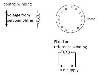
A.C servomotor is a two-phase ac induction motor. There are two windings in this motor, one is fixed or reference winding is supplied with a fixed voltage and frequency from a constant voltage source. Second winding is control winding with variable supply voltage of same frequency as reference winding but having a phase displacement of 900 electrical. A flux is induced due to the phase change which cuts the conducting bars of rotor and causes a time varying current, this current produces a time varying flux and reacts with the stator flux causing the rotor to rotate.
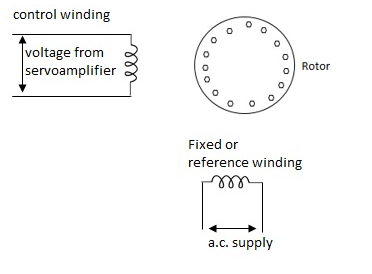
The rotor of A.C. Servomotos are of two types,
(a). Squirrel Cage Rotor
(b). Drag cup type rotor
(a). Squirrel cage rotor: They have high resistance as the rotor is having large length and small diameter. The air gap here is kept small.

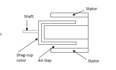
(b). Drag cup type motor: For the drag cup rotor there are two air gaps. For the rotor a cup of non-magnetic conducting material is used. A stationary iron core is placed between the conducting cup to complete the magnetic circuit. The resistance of drag cup type is high and therefore, has high starting torque. Generally aluminium is used for cup.
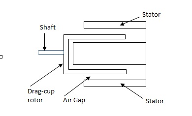
Torque-speed characteristic:
The torque speed characteristics of the two phase servomotor depends on ratio of reactance to resistance(X/R).

(i). For high ‘R’ and low X, the characteristic is linear and
(ii). For high X and low R, it becomes non-linear.
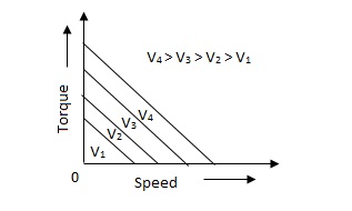
The torque-speed characteristic for various voltage is almost linear.
Q10) What are tachometers and list the difference between its types?
A10) These are electromechanical devices which convert mechanical input at their shaft to corresponding electrical output. It is basically used to measure speed of motor. It has negative feedback. These devices are most commonly used to find speed of any rotating machine.
| D.C. Tachometer | A.C. Tachometer |
1. | They convert rotational speed into a proportional dc voltage. | They convert the rotational speed into a proportional ac voltage. |
2. | It uses a permanent magnet for producing magnetic field. It contains iron core rotor. | It works on principle of induction generator. |
3. | The permanent magnet controls the magnetic field therefore the induce voltage at terminal of armature is proportional to shaft speed. | The reference winding is supplied by reference voltage and the output voltage is induced across the output winding. |
4. | The polarity depends on direction of rotation. | The amplitude and phase depends on the direction of rotation. |
Q11) Explain synchros transformer?
A11) Its basic working principle is similar to the synchro transformer. Here the rotor is cylindrical type. It is an electromechanical device. The combination of synchro transmitter and synchro transformer is used as an error detector.
The basic diagram is shown below,
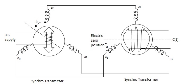
Fig 7. Synchros Transformers
Let transmitter rotate at an angle ϴ and control transformer rotor rotate in same direction through α. Then,
φ = ( 90 - ϴ + α )
Voltage across rotor terminal is given as,
e(t) = K1Vrcos ϴSinwot
e(t) = K1VrSin(ϴ - α) Sin wot
From above equation we can conclude that when two rotor shafts are not aligned, the rotor voltage of transformer is a sine function of difference between two angles.
For small angular displacement between two rotor position
e(t) = K1Vr(ϴ - α)Sinwot
Unit - 2
Effect of feedback on parameter variations
Q1) Differentiate between AC and DC Tachometer?
A2)
| D.C. Tachometer | A.C. Tachometer |
1. | They convert rotational speed into a proportional dc voltage. | They convert the rotational speed into a proportional ac voltage. |
2. | It uses a permanent magnet for producing magnetic field. It contains iron core rotor. | It works on principle of induction generator. |
3. | The permanent magnet controls the magnetic field therefore the induce voltage at terminal of armature is proportional to shaft speed. | The reference winding is supplied by reference voltage and the output voltage is induced across the output winding. |
4. | The polarity depends on direction of rotation. | The amplitude and phase depends on the direction of rotation. |
Q2) Explain how we could get control over the system dynamics by use of feedback?
A2)
The dynamics of the system can be controlled by the feedback by adjusting the location of poles. In this section we will see how the location of poles effect the dynamics of the system.
Let us consider a system which has open loop transfer function of G(s) defined as
G(s) =  (1)
(1)
Let K =  /
/
 = 1/
= 1/
The poles for the above system lie at s= - and
and  =1/
=1/ is time constant.
The dc gain of the system is given by G(0) = K =  /
/
For closed loop system the transfer function is given by
 (2)
(2)
 =
= 
 =
=  /(1+K)
The above equation shows that due to feedback the system pole shifts from - to (–
to (– +K’). Due to this change the dynamic response of the system is also affected. For studying the dynamic response, we assume that the input to the system is an impulse.
r(t) =  (t)
(t)
And it can also be written as
R(s) = 1
Taking inverse Laplace transform of equation 1 we get
For open loop system
c(t) = K’
Taking inverse Laplace transform of equation 2 we get
For closed loop system
c(t) = K’
The system dynamic response decays in both the open system as well as closed loop system. The closed loop system time constant is  =
=  /(1+K) so its response decays faster than open loop system by factor of (1+K).
Q3) Explain Ziegler Nichols method for tuning of controllers?
A3) They proposed the rules for determining values of proportional gain kp, derivative time Td and integral time Ti. They have proposed from (1) methods.
1) First Method: The basic PID controller is shown in figure below. In this method a unit step response of a plant. Is obtained if the plant has neither integrator non dominant complex conjugal poles, then the output step curve is of shape s. As shown below. These curves are generated experimentally.
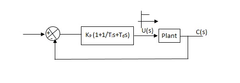
Fig 1. PID CONTROLLER
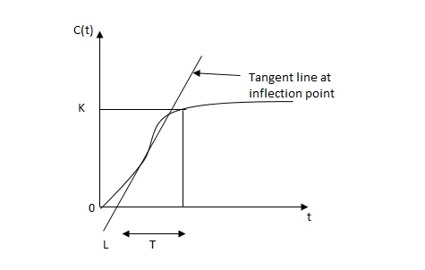
FIG 2. S-SHAPED RESPONSE CURVE

c(s) / l(s) = ke-l1s / ts+1
The values of KP, Ti and td should be set according to the table suggested by Ziegler Nichols tuning rules shown below.
Type of controller
Types of controller | Kp | Ti | Td |
P | T/L | 00 | 0 |
PI | 0.9T/L | L/0.3 | 0 |
PID | 1.2T/L | 2L | 0.5L |
Controller gain Gc(s)= kp(1+1/Tis+Tds)
= 1.2T / L(1+1 / 2LS+0.5 LS)
= 1.2t/l+0.6t / L2S+0.6TS
= 0.6T(2/L+1/L2S+S)
Gc(s) = 0.6 T(S+1/L)2/S
Thus, the PID controller has a pole at the origin and double zeros at S=-1/ L
2) Second Method
1) Firstly, set Ti= and Td=0
2) Use proportional control action only, increase kp from 0 to Kcr (Critical value).
3)Then Kcr and pcr (period) are determined experimentally.

Fig 3 closed loop with proportional controller
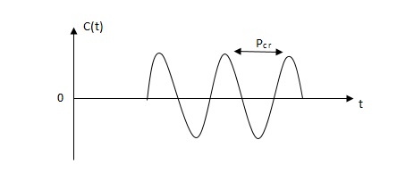
Fig 4 sustained oscillation with period pcr.
4)For this method Ziegler Nichols suggested new set of values for kp ,ti and td shown in table below.
Types of controller | KP | TI | Td |
P | 0.5Kcr |  | 0 |
PI | 0.45 KCR | 1/1.2PCR | 0 |
PID | 0.6KCR | 0.5PCR | 0.125PCR |
|
|
|
|
GC(S) = KP(1.1/Tis+Tds)
=0.6 Kcr(1+1/0.5PcrS+ 0.125 PCRS)
=0.075 KcrPcr(s+4/Pcr)2 / s
Thus, the PID controller has a pole at the origin and double zeros at s= -4/Pcr
Q4) What is effect of feedback on parameter variations?
A4)
The feedback systems are having many advantages over the non-feedback system as we have seen earlier. So, some performance parameters can be controlled through this feedback system such as sensitivity, noise etc. Sensitivity is a parameter which forecasts the effectiveness of feedback in reducing the influence of these variations on system performance.
The output of the open loop system is given by
C(s) = G(s)R(s)
Now due to variation in parameters G(s) changes to [G(s)+G(s)]. The output will now become
C(s)+ C(s) = [G(s)+ G(s)] R(s)
C(s) = G(s)R(s)
For closed loop system the output is given as

Now due to variation in parameters it becomes

The above equation shows that if there is variation in parameters then G(s) is reduced by factor of 1+G(s)H(s). The variation in overall transfer function T(s) due to change in G(s) is defined as sensitivity.

When there is small change in G(s) then sensitivity becomes

 : Sensitivity of T w.r.t G
For closed loop system the sensitivity will be

For open loop system

As T=G
The sensitivity of T w.r.t H is given as

The above equation shows that for large values of GH sensitivity of the feedback system w.r.t H approaches to unity.
Q5) Explain how feedback signal helps to control the disturbance signal in control system?
A5)
The feedback helps to control the disturbances as they generate an error signal. The signal flow graph for closed loop system is given by
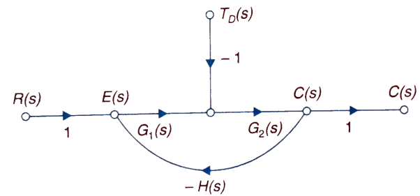
Fig 5. Closed loop system with disturbance signal
 =
= 
Where:
TD(s) = Disturbance signal.
For |G1G2H(s)|>>1 over the range of s
 =
=
The signal flow graph of a system with noise signal N(s) in the feedback path. The gain is given by
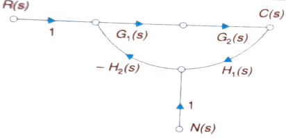
Fig 6. SFG for noise feedback function
 =
= 
For  >>1
>>1
Cn(s) = 
The feedback reduces sensitivity, improves transient response and minimises the effects of disturbance signal in control system.
Q6) What are the components of control system explain? Taking an example explain the state equation of any electrical network?
A6)
A closed loop control system consists of three basic elements: the feedback element, controller and controlled system. The controller consists of error detector and control elements.

The control element manipulates the actuating signal preferably to different power stage so as to fed to the controlled system. The power stage in control elements is essential for the control signal to drive controlled system. Control elements plays a vital role to get the desired output.
Electrical System
Applying Kirchoff’s voltage Law
V= Ri +Ldi/dt +1/cidt
V= Rdq/dt + L d2q/dt2+q/c
Now By kirchoff’s current low
I= V/R+ 1/L vdt+ cdv/dt
But V= dø/dt
I= 1/R dø/dt + 1/L ø+cd2ø/dt2
But v= dø/dt
I= 1/R dø/dt+ 1/L. ø+c d2ø/dt2
Q7) For the given mechanical system below draw the analogous system (force. Voltage) & find V0(s)/V1(s)
A7)
Form the table above we can find the analogus values of system components.
(1) Consider two displacement as two nodes.
(2) If masses are present connect them to reference lines
(3) Connect other elements of system to the nodes
(4) Applying modal analysis to find the system equation.
Let Z1 = R2 11 1/c2
=R2*1/c2s/R2+1/c2s
Z1= R2/1+R2c2s
Let Z2 = R1+1/c1s
Z2= 1+R1c1s/c1s
V0(s)/vi(s) = z2/z1+z2
= 1+R1c1s/c1s/R2/1+R2c2s+1+R1c1s/c1s
V0(s)/v0(s) =(c1+R1c1s) (1+R2c2s)/R2c1s+1+sR1c1s2R1R2c1c2
Q8) What are magnetic amplifiers, explain its working and types?
A8)
They are basically electromagnetic device used for amplification of electrical signals. The basic working of this amplifier depends on the saturation of core principle. It consists of two cores connected in opposite phases, with control and AC winding. By applying small amount of DC currents on control winding large amount of current on AC winding can be controlled. They are of two types
a) Half wave magnetic amplifier: When DC supply is given to the control winding the magnetic flux is generated in the iron core. As flux increases the output impedance decreases and the current through AC winding in output increases. Here only half cycle of AC is utilised.
If the current through the control winding is zero, then the impedance of the output winding will be very high making no current to flow through the load or output winding. A diode is connected to the output winding which acts as a rectifier, used for reversing the polarity of the AC supply constantly from cancelling out control winding flux.
b) Full wave magnetic amplifier: It utilizes both the half cycles of the AC supply. Due to wound of the two halves of the output winding the direction of magnetic flux created by these two halves in centre leg is same as direction of control winding flux
No control voltage is supplied there will be some flux present in magnetic core, hence impedance of the output winding will never attain its maximum value and current through load never attain its minimum value. The operation of the amplifier can be controlled by using the bias winding.
Q9) Explain servomechanism and ac servomotor with torque speed characteristics?
A9)
Servomechanism is also called servo which is a device usually error sensing device connected as a feedback element to correct the action of a mechanism. Here instead of controlling a device by variable input signal, the device is controlled by feedback signal.
The input signal applied to such systems generate the required output which is compared again to the input signal. If the device achieves its desired output, there will be no longer the logical difference between the two signals. Hence, the primary task of servomechanism is to maintain the output of a system at the desired value in the presence of disturbances.
A.C. Servomotors:
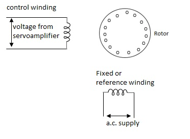
A.C servomotor is a two-phase ac induction motor. There are two windings in this motor, one is fixed or reference winding is supplied with a fixed voltage and frequency from a constant voltage source. Second winding is control winding with variable supply voltage of same frequency as reference winding but having a phase displacement of 900 electrical. A flux is induced due to the phase change which cuts the conducting bars of rotor and causes a time varying current, this current produces a time varying flux and reacts with the stator flux causing the rotor to rotate.
The rotor of A.C. Servomotos are of two types,
(a). Squirrel Cage Rotor
(b). Drag cup type rotor
(a). Squirrel cage rotor: They have high resistance as the rotor is having large length and small diameter. The air gap here is kept small.

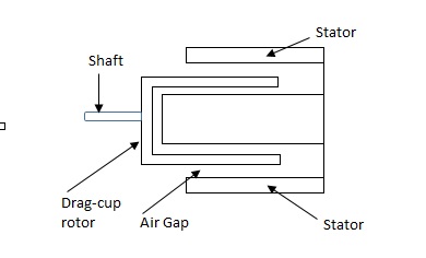
(b). Drag cup type motor: For the drag cup rotor there are two air gaps. For the rotor a cup of non-magnetic conducting material is used. A stationary iron core is placed between the conducting cup to complete the magnetic circuit. The resistance of drag cup type is high and therefore, has high starting torque. Generally aluminium is used for cup.
Torque-speed characteristic:
The torque speed characteristics of the two phase servomotor depends on ratio of reactance to resistance(X/R).
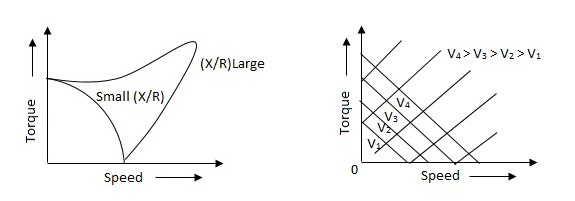
(i). For high ‘R’ and low X, the characteristic is linear and
(ii). For high X and low R, it becomes non-linear.
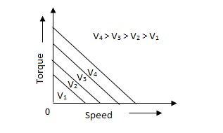
The torque-speed characteristic for various voltage is almost linear.
Q10) What are tachometers and list the difference between its types?
A10) These are electromechanical devices which convert mechanical input at their shaft to corresponding electrical output. It is basically used to measure speed of motor. It has negative feedback. These devices are most commonly used to find speed of any rotating machine.
| D.C. Tachometer | A.C. Tachometer |
1. | They convert rotational speed into a proportional dc voltage. | They convert the rotational speed into a proportional ac voltage. |
2. | It uses a permanent magnet for producing magnetic field. It contains iron core rotor. | It works on principle of induction generator. |
3. | The permanent magnet controls the magnetic field therefore the induce voltage at terminal of armature is proportional to shaft speed. | The reference winding is supplied by reference voltage and the output voltage is induced across the output winding. |
4. | The polarity depends on direction of rotation. | The amplitude and phase depends on the direction of rotation. |
Q11) Explain synchros transformer?
A11) Its basic working principle is similar to the synchro transformer. Here the rotor is cylindrical type. It is an electromechanical device. The combination of synchro transmitter and synchro transformer is used as an error detector.
The basic diagram is shown below,
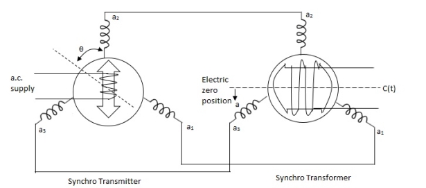
Fig 7. Synchros Transformers
Let transmitter rotate at an angle ϴ and control transformer rotor rotate in same direction through α. Then,
φ = ( 90 - ϴ + α )
Voltage across rotor terminal is given as,
e(t) = K1Vrcos ϴSinwot
e(t) = K1VrSin(ϴ - α) Sin wot
From above equation we can conclude that when two rotor shafts are not aligned, the rotor voltage of transformer is a sine function of difference between two angles.
For small angular displacement between two rotor position
e(t) = K1Vr(ϴ - α)Sinwot
Unit - 2
Unit - 2
Unit - 2
Unit - 2
Effect of feedback on parameter variations
Q1) Differentiate between AC and DC Tachometer?
A2)
| D.C. Tachometer | A.C. Tachometer |
1. | They convert rotational speed into a proportional dc voltage. | They convert the rotational speed into a proportional ac voltage. |
2. | It uses a permanent magnet for producing magnetic field. It contains iron core rotor. | It works on principle of induction generator. |
3. | The permanent magnet controls the magnetic field therefore the induce voltage at terminal of armature is proportional to shaft speed. | The reference winding is supplied by reference voltage and the output voltage is induced across the output winding. |
4. | The polarity depends on direction of rotation. | The amplitude and phase depends on the direction of rotation. |
Q2) Explain how we could get control over the system dynamics by use of feedback?
A2)
The dynamics of the system can be controlled by the feedback by adjusting the location of poles. In this section we will see how the location of poles effect the dynamics of the system.
Let us consider a system which has open loop transfer function of G(s) defined as
G(s) =  (1)
(1)
Let K =  /
/
 = 1/
= 1/
The poles for the above system lie at s= - and
and  =1/
=1/ is time constant.
The dc gain of the system is given by G(0) = K =  /
/
For closed loop system the transfer function is given by
 (2)
(2)
 =
= 
 =
=  /(1+K)
The above equation shows that due to feedback the system pole shifts from - to (–
to (– +K’). Due to this change the dynamic response of the system is also affected. For studying the dynamic response, we assume that the input to the system is an impulse.
r(t) =  (t)
(t)
And it can also be written as
R(s) = 1
Taking inverse Laplace transform of equation 1 we get
For open loop system
c(t) = K’
Taking inverse Laplace transform of equation 2 we get
For closed loop system
c(t) = K’
The system dynamic response decays in both the open system as well as closed loop system. The closed loop system time constant is  =
=  /(1+K) so its response decays faster than open loop system by factor of (1+K).
Q3) Explain Ziegler Nichols method for tuning of controllers?
A3) They proposed the rules for determining values of proportional gain kp, derivative time Td and integral time Ti. They have proposed from (1) methods.
1) First Method: The basic PID controller is shown in figure below. In this method a unit step response of a plant. Is obtained if the plant has neither integrator non dominant complex conjugal poles, then the output step curve is of shape s. As shown below. These curves are generated experimentally.
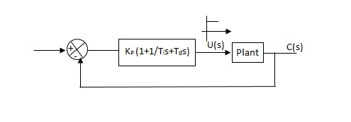
Fig 1. PID CONTROLLER
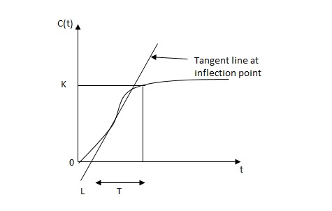
FIG 2. S-SHAPED RESPONSE CURVE

c(s) / l(s) = ke-l1s / ts+1
The values of KP, Ti and td should be set according to the table suggested by Ziegler Nichols tuning rules shown below.
Type of controller
Types of controller | Kp | Ti | Td |
P | T/L | 00 | 0 |
PI | 0.9T/L | L/0.3 | 0 |
PID | 1.2T/L | 2L | 0.5L |
Controller gain Gc(s)= kp(1+1/Tis+Tds)
= 1.2T / L(1+1 / 2LS+0.5 LS)
= 1.2t/l+0.6t / L2S+0.6TS
= 0.6T(2/L+1/L2S+S)
Gc(s) = 0.6 T(S+1/L)2/S
Thus, the PID controller has a pole at the origin and double zeros at S=-1/ L
2) Second Method
1) Firstly, set Ti= and Td=0
2) Use proportional control action only, increase kp from 0 to Kcr (Critical value).
3)Then Kcr and pcr (period) are determined experimentally.

Fig 3 closed loop with proportional controller
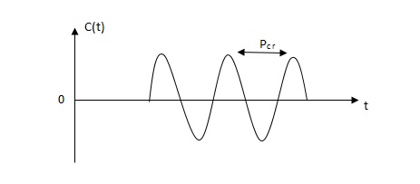
Fig 4 sustained oscillation with period pcr.
4)For this method Ziegler Nichols suggested new set of values for kp ,ti and td shown in table below.
Types of controller | KP | TI | Td |
P | 0.5Kcr |  | 0 |
PI | 0.45 KCR | 1/1.2PCR | 0 |
PID | 0.6KCR | 0.5PCR | 0.125PCR |
|
|
|
|
GC(S) = KP(1.1/Tis+Tds)
=0.6 Kcr(1+1/0.5PcrS+ 0.125 PCRS)
=0.075 KcrPcr(s+4/Pcr)2 / s
Thus, the PID controller has a pole at the origin and double zeros at s= -4/Pcr
Q4) What is effect of feedback on parameter variations?
A4)
The feedback systems are having many advantages over the non-feedback system as we have seen earlier. So, some performance parameters can be controlled through this feedback system such as sensitivity, noise etc. Sensitivity is a parameter which forecasts the effectiveness of feedback in reducing the influence of these variations on system performance.
The output of the open loop system is given by
C(s) = G(s)R(s)
Now due to variation in parameters G(s) changes to [G(s)+G(s)]. The output will now become
C(s)+ C(s) = [G(s)+ G(s)] R(s)
C(s) = G(s)R(s)
For closed loop system the output is given as

Now due to variation in parameters it becomes

The above equation shows that if there is variation in parameters then G(s) is reduced by factor of 1+G(s)H(s). The variation in overall transfer function T(s) due to change in G(s) is defined as sensitivity.

When there is small change in G(s) then sensitivity becomes

 : Sensitivity of T w.r.t G
For closed loop system the sensitivity will be

For open loop system

As T=G
The sensitivity of T w.r.t H is given as

The above equation shows that for large values of GH sensitivity of the feedback system w.r.t H approaches to unity.
Q5) Explain how feedback signal helps to control the disturbance signal in control system?
A5)
The feedback helps to control the disturbances as they generate an error signal. The signal flow graph for closed loop system is given by
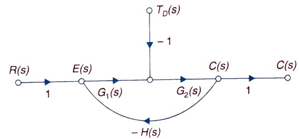
Fig 5. Closed loop system with disturbance signal
 =
= 
Where:
TD(s) = Disturbance signal.
For |G1G2H(s)|>>1 over the range of s
 =
=
The signal flow graph of a system with noise signal N(s) in the feedback path. The gain is given by
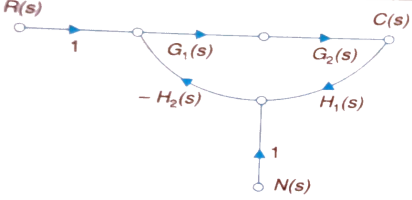
Fig 6. SFG for noise feedback function
 =
= 
For  >>1
>>1
Cn(s) = 
The feedback reduces sensitivity, improves transient response and minimises the effects of disturbance signal in control system.
Q6) What are the components of control system explain? Taking an example explain the state equation of any electrical network?
A6)
A closed loop control system consists of three basic elements: the feedback element, controller and controlled system. The controller consists of error detector and control elements.

The control element manipulates the actuating signal preferably to different power stage so as to fed to the controlled system. The power stage in control elements is essential for the control signal to drive controlled system. Control elements plays a vital role to get the desired output.
Electrical System
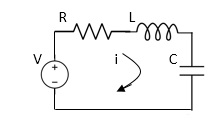
Applying Kirchoff’s voltage Law
V= Ri +Ldi/dt +1/cidt
V= Rdq/dt + L d2q/dt2+q/c
Now By kirchoff’s current low
I= V/R+ 1/L vdt+ cdv/dt
But V= dø/dt
I= 1/R dø/dt + 1/L ø+cd2ø/dt2
But v= dø/dt
I= 1/R dø/dt+ 1/L. ø+c d2ø/dt2
Q7) For the given mechanical system below draw the analogous system (force. Voltage) & find V0(s)/V1(s)
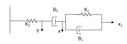
A7)
Form the table above we can find the analogus values of system components.
(1) Consider two displacement as two nodes.
(2) If masses are present connect them to reference lines
(3) Connect other elements of system to the nodes
(4) Applying modal analysis to find the system equation.
Let Z1 = R2 11 1/c2
=R2*1/c2s/R2+1/c2s
Z1= R2/1+R2c2s
Let Z2 = R1+1/c1s
Z2= 1+R1c1s/c1s
V0(s)/vi(s) = z2/z1+z2
= 1+R1c1s/c1s/R2/1+R2c2s+1+R1c1s/c1s
V0(s)/v0(s) =(c1+R1c1s) (1+R2c2s)/R2c1s+1+sR1c1s2R1R2c1c2
Q8) What are magnetic amplifiers, explain its working and types?
A8)
They are basically electromagnetic device used for amplification of electrical signals. The basic working of this amplifier depends on the saturation of core principle. It consists of two cores connected in opposite phases, with control and AC winding. By applying small amount of DC currents on control winding large amount of current on AC winding can be controlled. They are of two types
a) Half wave magnetic amplifier: When DC supply is given to the control winding the magnetic flux is generated in the iron core. As flux increases the output impedance decreases and the current through AC winding in output increases. Here only half cycle of AC is utilised.
If the current through the control winding is zero, then the impedance of the output winding will be very high making no current to flow through the load or output winding. A diode is connected to the output winding which acts as a rectifier, used for reversing the polarity of the AC supply constantly from cancelling out control winding flux.
b) Full wave magnetic amplifier: It utilizes both the half cycles of the AC supply. Due to wound of the two halves of the output winding the direction of magnetic flux created by these two halves in centre leg is same as direction of control winding flux
No control voltage is supplied there will be some flux present in magnetic core, hence impedance of the output winding will never attain its maximum value and current through load never attain its minimum value. The operation of the amplifier can be controlled by using the bias winding.
Q9) Explain servomechanism and ac servomotor with torque speed characteristics?
A9)
Servomechanism is also called servo which is a device usually error sensing device connected as a feedback element to correct the action of a mechanism. Here instead of controlling a device by variable input signal, the device is controlled by feedback signal.
The input signal applied to such systems generate the required output which is compared again to the input signal. If the device achieves its desired output, there will be no longer the logical difference between the two signals. Hence, the primary task of servomechanism is to maintain the output of a system at the desired value in the presence of disturbances.
A.C. Servomotors:
A.C servomotor is a two-phase ac induction motor. There are two windings in this motor, one is fixed or reference winding is supplied with a fixed voltage and frequency from a constant voltage source. Second winding is control winding with variable supply voltage of same frequency as reference winding but having a phase displacement of 900 electrical. A flux is induced due to the phase change which cuts the conducting bars of rotor and causes a time varying current, this current produces a time varying flux and reacts with the stator flux causing the rotor to rotate.
The rotor of A.C. Servomotos are of two types,
(a). Squirrel Cage Rotor
(b). Drag cup type rotor
(a). Squirrel cage rotor: They have high resistance as the rotor is having large length and small diameter. The air gap here is kept small.

(b). Drag cup type motor: For the drag cup rotor there are two air gaps. For the rotor a cup of non-magnetic conducting material is used. A stationary iron core is placed between the conducting cup to complete the magnetic circuit. The resistance of drag cup type is high and therefore, has high starting torque. Generally aluminium is used for cup.
Torque-speed characteristic:
The torque speed characteristics of the two phase servomotor depends on ratio of reactance to resistance(X/R).
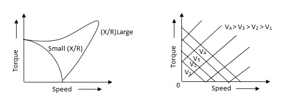
(i). For high ‘R’ and low X, the characteristic is linear and
(ii). For high X and low R, it becomes non-linear.
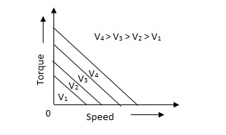
The torque-speed characteristic for various voltage is almost linear.
Q10) What are tachometers and list the difference between its types?
A10) These are electromechanical devices which convert mechanical input at their shaft to corresponding electrical output. It is basically used to measure speed of motor. It has negative feedback. These devices are most commonly used to find speed of any rotating machine.
| D.C. Tachometer | A.C. Tachometer |
1. | They convert rotational speed into a proportional dc voltage. | They convert the rotational speed into a proportional ac voltage. |
2. | It uses a permanent magnet for producing magnetic field. It contains iron core rotor. | It works on principle of induction generator. |
3. | The permanent magnet controls the magnetic field therefore the induce voltage at terminal of armature is proportional to shaft speed. | The reference winding is supplied by reference voltage and the output voltage is induced across the output winding. |
4. | The polarity depends on direction of rotation. | The amplitude and phase depends on the direction of rotation. |
Q11) Explain synchros transformer?
A11) Its basic working principle is similar to the synchro transformer. Here the rotor is cylindrical type. It is an electromechanical device. The combination of synchro transmitter and synchro transformer is used as an error detector.
The basic diagram is shown below,
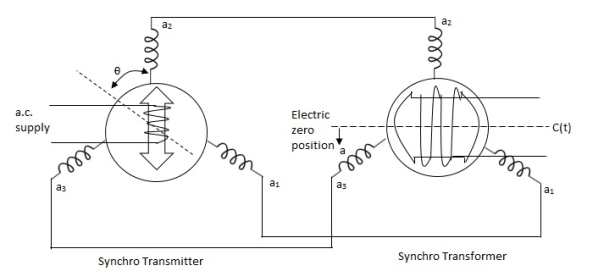
Fig 7. Synchros Transformers
Let transmitter rotate at an angle ϴ and control transformer rotor rotate in same direction through α. Then,
φ = ( 90 - ϴ + α )
Voltage across rotor terminal is given as,
e(t) = K1Vrcos ϴSinwot
e(t) = K1VrSin(ϴ - α) Sin wot
From above equation we can conclude that when two rotor shafts are not aligned, the rotor voltage of transformer is a sine function of difference between two angles.
For small angular displacement between two rotor position
e(t) = K1Vr(ϴ - α)Sinwot