Unit - 3
Time response of system
Q1) Find the initial value for the function f(t) = 2u(t)+3cost u(t)?
A1)
f(t) = 2u(t)+3cost u(t)
F(s) = 
SF(s) = 2+ 
By initial value theorem
 = f(0+)
 =
=  2+
2+  = 5 = f(0+)
Hence, initial value of the function is 5
Q2) Find final value of the function F(s) = 
A2)
F(s) = 
SF(s) = 
By final value theorem
 =
= 
 =
=  = 0.1
= 0.1
So, final value of the function is 0.1
Q3) The open loop transfer function of a system with unity feedback gain G( S ) = 20 / S2 + 5S + 4. Determine the ξ, Mp, tr, tp.
A3)
Finding closed loop transfer function,
C( S ) / R( S ) = G( S ) / 1 + G( S ) + H( S )
As it is unity feedback so, H(S) = 1
C(S)/R(S) = G(S)/1 + G(S)
= 20/S2 + 5S + 4/1 + 20/S2 + 5S + 4
C(S)/R(S) = 20/S2 + 5S + 24
Standard equation for second order system,
S2 + 2ξWnS + Wn2 = 0
We have,
S2 + 5S + 24 = 0
Wn2 = 24
Wn = 4.89 rad/sec
2ξWn = 5
(a). ξ = 5/2 x 4.89 = 0.511
(b). Mp% = e-∏ξ / √1 –ξ2 x 100
= e-∏ x 0.511 / √1 – (0.511)2 x 100
Mp% = 15.4%
(c). tr = ∏ - φ / Wd
φ = tan-1√1 – ξ2 / ξ
φ= tan-1√1 – (0.511)2 / (0.511)
φ = 1.03 rad.
tr = ∏ - 1.03/Wd
Wd = Wn√1 – ξ2
= 4.89 √1 – (0.511)2
Wd = 4.20 rad/sec
tr = ∏ - 1.03/4.20
tr = 502.34 msec
(d). tp = ∏/4.20 = 747.9 msec
Q4) A second order system has Wn = 5 rad/sec and is ξ = 0.7 subjected to unit step input. Find (i) closed loop transfer function. (ii) Peak time (iii) Rise time (iv) Settling time (v) Peak overshoot.
A4)
The closed loop transfer function is
C(S)/R(S) = Wn2 / S2 + 2ξWnS + Wn2
= (5)2 / S2 + 2 x 0.7 x S + (5)2
C(S)/R(S) = 25 / S2 + 7s + 25
(ii). tp = ∏ / Wd
Wd = Wn√1 - ξ2
= 5√1 – (0.7)2
= 3.571 sec
(iii). tr = ∏ - φ/Wd
φ= tan-1√1 – ξ2 / ξ = 0.795 rad
tr = ∏ - 0.795 / 3.571
tr = 0.657 sec
(iv). For 2% settling time
ts = 4 / ξWn = 4 / 0.7 x 5
ts = 1.143 sec
(v). Mp = e-∏ξ / √1 –ξ2 x 100
Mp = 4.59%
Q5) The open loop transfer function of a unity feedback control system is given by G(S) = K/S(1 + ST). Calculate the value by which k should be multiplied so that damping ratio is increased from 0.2 to 0.4?
A5)
C(S)/R(S) = G(S) / 1 + G(S)H(S) H(S) = 1
C(S)/R(S) = K/S(1 + ST) / 1 + K/S(1 + ST)
C(S)/R(S) = K/S(1 + ST) + K
C(S)/R(S) = K/T / S2 + S/T + K/T
For second order system,
S2 + 2ξWnS + Wn2
2ξWn = 1/T
ξ = 1/2WnT
Wn2 = K/T
Wn =√K/T
ξ = 1 / 2√K/T T
ξ = 1 / 2 √KT
Forξ1 = 0.2, for ξ2 = 0.4
ξ1 = 1 / 2 √K1T
ξ2 = 1 / 2 √K2T
ξ1/ ξ2 = √K2/K1
K2/K1 = (0.2/0.4)2
K2/K1 = 1 / 4
K1 = 4K2
Q6) Consider the transfer function C(S)/R(S) = Wn2 / S2 + 2ξWnS + Wn2. Find ξ, Wn so that the system responds to a step input with 5% overshoot and settling time of 4 sec?
A6)
Mp = 5% = 0.05
Mp = e-∏ξ / √1 –ξ2
0.05 = e-∏ξ / √1 –ξ2
Cn 0.05 = - ∏ξ / √1 –ξ2
-2.99 = - ∏ξ / √1 –ξ2
8.97(1 – ξ2) = ξ2∏2
0.91 – 0.91 ξ2 = ξ2
0.91 = 1.91 ξ2
ξ2 = 0.69
(ii). ts = 4/ ξWn
4 = 4/ ξWn
Wn = 1/ ξ = 1/ 0.69
Wn = 1.45 rad/sec
Q7) The block diagram of a system using PI controllers is shown in the figure below Calculate:
(a). The steady state without and with controller for unit step input?
(b). Determine TF of newly constructed sys. With controller so, that a CL Poles is located at -5?

A7)
(a). Without:
C(S)/R(S) = 0.2/(S + 1)
C(S) = R(S) 0.2/(S + 1) + 0.2
For unit step
Ess = 1/1 + Kp
Kp = lt G(S)
S 0
= lt 0.2/(S + 1)
S 0
Kp = 0.2
Ess = 1/1.2 = 5/6 = 0.8
(b). With controller:
Gc(S) = Kp + Ki/S
G’(S) = Gc(S).G(S)
= ( Kp + Ki/S )0.2/(S + 1)
= (KpS + Ki)0.2/S(S + 1)
Ess = 1/1 + Kp = 0
So, the value of ess is decreased.
(b). Given
Kpi/Kp = 0.1
G’(S) = (Kp + Ki/S)(0.2/S + 1)
= (KpS + Ki)0.2/S(S + 1)
As a pole is to be added so, we have to examine the CE,
1 + G’(S) = 0
1 + (Kp + Ki)0.2/S(S + 1) = 0
S2 + S + 0.2KpS + 0.2Ki = 0
S2 + (0.2Kp + 1)S + 0.2Ki = 0
Given,
Kpi = 0.1Ki
Kp = 10Ki
S2 + (2Ki + 1)S + 0.2Ki = 0
Pole at S = -5
25 + (2Ki + 1)(-5) + 0.2Ki = 0
-10Ki – 5 + 25 + 0.2Ki = 0
-9.8Ki = -20
Ki = 2.05
Kp = 10Ki
= 20.5
Now,
G’(S) = (KpS + Ki)(0.2)/S(S + 1)
= (20.5S + 2.05)(0.2)/S(S + 1)
G’(S) = 4.1S + 0.41/S(S + 1)
Q8) The block diagram of a system using Pd controller is shown, the PD is used to increase ξ to 0.8. Determine the T.F of controller?

A8)
(1). Kp = 1
Without controller:
C(S)/R(S) = 16/S2 + 1.6S + 16
wn = 4
2 ξwn = 16
ξ = 1.6/2 x 4 = 0.2
(b). With derivative:
ξS = 0.2 to 0.8
Undamped to critically damped,
G’(S) = (1 + KdS)(16)/(S2 + 1.6S)
CE:
S2 + 1.6S + 16(1 + KdS) = 0
S2 + (1.6 + Kd)S + 16 = 0
2 ξwn = 1.6 + Kd1.6
wn = 4
ξS = 0.8
2 x 4 x 0.8 = 1.6 + Kd1.6
6.4 – 1.6 = Kd1.6
4.8/16 = Kd
Kd = 0.3
TF = (1 + 0.3S)16/S(S + 16)
Q9) With help of waveform explain all the standard test signals?
A9)
The Impulse signal, Ramp signal, unit step and parabolic signals are used as the standard test signals. All these signals are explained below.
(a) Impulse Signal:
This signal has zero amplitude everywhere except at the origin. Fig below shown the representation of Impulse signal.
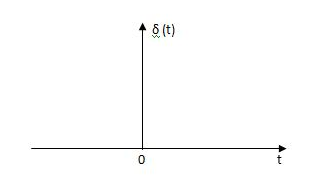
Fig. Unit Impulse Signal
The mathematical representations
A (t) = 0 for t ≠0
 dt = A e
Where A represent energy or area of the Laplace Transform of Impulse signal is
L [A (t)] = A
Unit Impulse Signal:
If A = 1
 (t) = 0 for t ≠0
L [ (t)] = 1
The transfer function of a linear time invariant
System is the Laplace transform of the impulse response of the system. If a unit impulse signal is applied to system then Laplace transform of the output c(s) is the transfer function G(s)
As we know G(s) = c(s)/R(S)
r(t) =  (t)
(t)
R(s) = L [ (t)] = 1
:. G(S) = C(s)
(b) Step signal:
Step signal of size A is a signal that change from zero level to A in zero time and stays there forever.
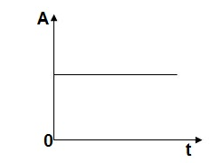
Fig. Unit Step Signal
r(t)= A t >=0
=0 t<0
L[r(t)] = R(s) = A/s
Unit Step Signal:
If the magnitude of the slip signal is I then it is called unit step signal.
u(t) = 1
t>=0
t<0
L[u(t)] = 1/s
(c) Ramp Signal:
The vamp signal increase linearly with time from initial value of zero at t= 0 as shown in fig is below
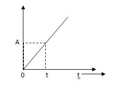
Fig. Ramp Signal
r(t) = At t>=0
=0 t<0
A is the slope of the line The Laplace transform of ramp signal is
L[r(t)] = R(s) = A/s2
(d) Parabolic Signal:
The instantaneous value of a parabolic signal varies as square of the time from an initial value of zero t=0. The signal representation in fig 14 below.
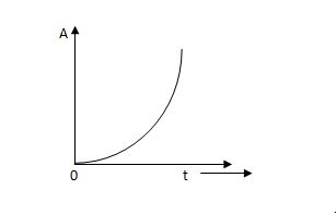
Fig. Parabolic Signal
r(t) At2 t>=0
=0 t<0
Then Laplace Transform is given as
R(s) = L[At2] = 2A/s3
If no error then E(t) =0, :. R(t) = c(t), output is tracking the input.
Steady state Errors signal (ess): - (t  )
)
Ess = t  e(t)
e(t)
Using final values, the theorem
 = ess =
  S.E (s)
ess=  S[R(s)/1+G/(s)]
Q10) For the CLTF G(s) =  . Find Kp, Kv and Ka?
A10)
Kp =  G(s)
G(s)
= 

= 1
Kv =  SG(s)
SG(s)
=  S
S 
= 0
Ka =  s2 G(s)
=  s2
s2 
= 0
Q11) For a unity feedback system G(s) =  an input t3u(t) is applied. Find the steady state error?
A11)
ess= 

r(t) = t3u(t)
R(s) = 6/s4
H(s) =1
ess= 

= 
= 
= 5/3
Q12) For the OLTF with unity feedback is G(s)=  . Determine the damping ratio, maximum overshoot, rise time?
A12)
The CLTF will be T(s) = 
T(s) = 
For second order system,
S2 + 2ξWnS + Wn2
wn =  = 5.1
= 5.1
2ξWn = 5
i) Damping Ratio  = 0.49
Ii) Maximum overshoot Mp = e-∏ξ / √1 –ξ2 x 100
= e-∏x0.49 / √1 –(0.49)2
= 17.1%
Iii) Rise Time tr = ∏ - φ/Wd
Wd = Wn√1 - ξ2
= 5.1 √1 – (0.49)2
= 4.45 sec
φ= tan-1√1 – ξ2 / ξ = 1.059 rad
tr = ∏ - φ/Wd
= ∏ - 1.059/4.45
=468.53msec
Q13) Define and derive the time domain specifications for a second order system?
A13)
1) Rise Time (tp)
The time taken by the output to reach the already status value for the first time is known as Rise time.
C(t) = 1-e- wnt/
wnt/ 1-
1- 2 sin (wdt+ø)
Sin (wd +ø) = 0
Wdt +ø = n
tr = n -ø/wd
-ø/wd
For first time so, n=1.
tr =  -ø/wd
-ø/wd
T=1/
2) Peak Time (tp)
The peak value attained by the output is called peak time. The time required by the output to reach this value is lp.
d(cct) /dt = 0 (maxima)
d(t)/dt = peak value
tp = n /wd for n=1
tp =  wd
wd
3) Peak Overshoot Value:
Maximum deviation of output from steady state value is called peak overshoot value (Mp).
(ltp) = 1 = Mp
( Sin(Wat + φ )
( Sin( Wd∏/Wd + φ)
Mp = e-∏ξ / √1 –ξ2
Condition 3 ξ = 1
C( S ) = R( S ) Wn2 / S2 + 2ξWnS + Wn2
C( S ) = Wn2 / S(S2 + 2WnS + Wn2) [ R(S) = 1/S ]
C( S ) = Wn2 / S( S2 + Wn2 )
C( t ) = 1 – e-Wnt + tWne-Wnt
The response is critically damped.
4) Settling Time (ts):
ts = 3 / ξWn ( 5% )
ts = 4 / ξWn ( 2% )
Q14) Determine the type and order of the system G(s)= K/S(S+1)
G(S)= K(S+1)/S2(S+2)
A14)
G(s)= K/S(S+1)
It is order 2 and type 1 system
G(S)= K(S+1)/S2(S+2)
It is order 3 and type 2 system
Q15) Derive position error coefficient?
A15)
R(s)= Unit step
R(t) = u(t)
R(s) = 1/s
Ess =  s[ R(s)/1+G(s)]
=  s[ys/1+G(s)]
ess=  1+1/1+G(s)
=1/1+lt G(s) s- 0
Kp =  G(s)
G(s)
(Position error coefficient)
Q16) What is sensitivity of a feedback system? Derive its expression?
A16)
The feedback systems are having many advantages over the non-feedback system as we have seen earlier. So, some performance parameters can be controlled through this feedback system such as sensitivity, noise etc. Sensitivity is a parameter which forecasts the effectiveness of feedback in reducing the influence of these variations on system performance. [Reference 4]
The output of the open loop system is given by
C(s) = G(s)R(s)
Now due to variation in parameters G(s) changes to [G(s)+ G(s)]. The output will now become
C(s)+ C(s) = [G(s)+
 G(s)] R(s)
 C(s) =
  G(s)R(s)
For closed loop system the output is given as
C(s) =  R(s)
R(s)
Now due to variation in parameters it becomes
C(s)+ C(s) =
 R(s)
R(s)
The above equation shows that if there is variation in parameters then G(s) is reduced by factor of 1+G(s)H(s). The variation in overall transfer function T(s) due to change in G(s) is defined as sensitivity.
Sensitivity = 
When there is small change in G(s) then sensitivity becomes

 : Sensitivity of T w.r.t G
For closed loop system the sensitivity will be
 =
=  x
x  =
= 
For open loop system
 = 1
= 1
As T=G
The sensitivity of T w.r.t H is given as
 =G [
=G [ ]
]  =
= 
The above equation shows that for large values of GH sensitivity of the feedback system w.r.t H approaches to unity.
Q17) What are the design consideration of Higher Order System?
A17)
The time domain analysis for second order system can be extended to third order system. Let transfer function for third order system be,
C(S)/R(S) = Wn2/(1 + ST)(S2 + 2ξWnS + Wn2)
Let 1/T = P
C(S)/R(S) = Wn2P/(S + P) (S2 + 2ξWnS + Wn2)
Taking Laplace inverse of above equation (for unit step response will be)
Cp(t) = 1 – K1e-pt + K2e-ξWntSin[ Wn√(1-ξ2)t - φ ]
Where K1 = Wn2 / Wn2 - 2ξWnp + p2
K2 = 1 / √1 – ξ2(1 - 2ξWn/p + Wn2/p2)
φ = tan-1√(1 – ξ2) / -ξ + tan-1Wn√1- ξ2/p – ξWn
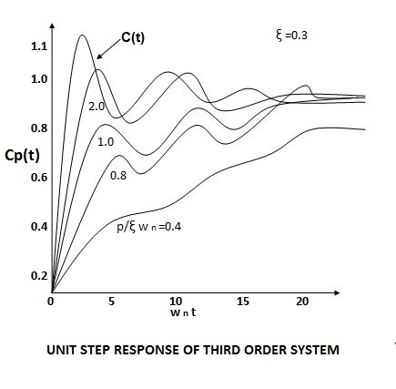
From above equations we can conclude that:
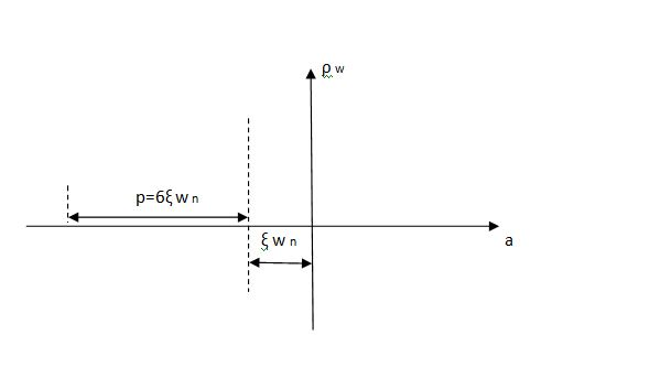
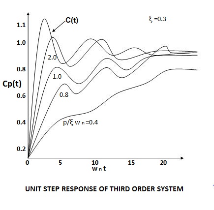
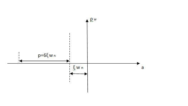
(1). The system has three poles S = -p and S = - ξWn+-√(1 – ξ2). So the position of these poles effect the system. As the pole S = -p moves towards the origin, the output Cp(t) is dominated by only this pole.
(2). As the pole S = -p moves away from the origin, the response Cp(t) is dominated by the complex poles at S = -ξWn+-(√1-ξ2)jWn.
The response of third order system is shown in figure.
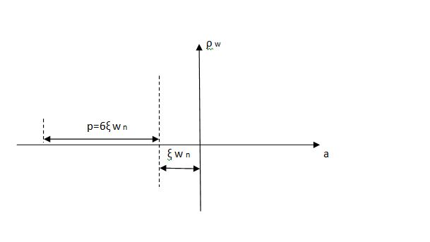
The relative location of dominant poles of the third order system is shown below in fig.
Q18) Explain the steady state and Transient response of a system?
A18)
The Response of the system as a function of time, to the applied excitation is called Time Response. The time response of a system can be fully studied by studying the following two responses

The total time response C(t) is given by
C(t) = Ctr(t) + Css(t)
Where Ctr(t) = transient response
Css(t) = steady state response
Consider the class of differential equation

Where the coefficient ai and bi are constant, u = u(t) (the input) is a known time function, and y = y(t) (the output) is the unknown solution of the equation. Generally, m ≤ n, and n is called the order of the differential equation.
The Free Response
The Free response of a differential equation is the solution of the differential equation when the input u(t) is identically zero. If the input u(t) is identically zero, then the differential equation has the form:

The solution y(t) of such an equation depends only on the initial conditions.
The Forced Response
The forced response yb(t) of a differential equation is the solution of the differential equation when all the initial conditions are identically zero.

The Total Response
The total response of a linear constant −coefficient differential equation is the sum of the free response and the forced response.
The Steady State and Transient Response
The steady state response and transient response are another pair of quantities whose sum is equal to the total response. These terms are often used for specifying control system performance. They are defined as follows. The steady state response is that part of the total response which does not approach zero as time approaches infinity. The transient response is that part of the total response which approaches zero as time approaches infinity
For stable system Transient response vanishes after some time to get final value closer to the desired value.
Steady State Response: The part of the time response which remains after complete transient response vanishes from the system output. The steady state response is generally the final value achieved by the system output. The difference between the desired output and the actual output of the system is called as Steady state error (ess) and the time taken to reach steady state is called Settling time.
Unit - 3
Time response of system
Q1) Find the initial value for the function f(t) = 2u(t)+3cost u(t)?
A1)
f(t) = 2u(t)+3cost u(t)
F(s) = 
SF(s) = 2+ 
By initial value theorem
 = f(0+)
 =
=  2+
2+  = 5 = f(0+)
Hence, initial value of the function is 5
Q2) Find final value of the function F(s) = 
A2)
F(s) = 
SF(s) = 
By final value theorem
 =
= 
 =
=  = 0.1
= 0.1
So, final value of the function is 0.1
Q3) The open loop transfer function of a system with unity feedback gain G( S ) = 20 / S2 + 5S + 4. Determine the ξ, Mp, tr, tp.
A3)
Finding closed loop transfer function,
C( S ) / R( S ) = G( S ) / 1 + G( S ) + H( S )
As it is unity feedback so, H(S) = 1
C(S)/R(S) = G(S)/1 + G(S)
= 20/S2 + 5S + 4/1 + 20/S2 + 5S + 4
C(S)/R(S) = 20/S2 + 5S + 24
Standard equation for second order system,
S2 + 2ξWnS + Wn2 = 0
We have,
S2 + 5S + 24 = 0
Wn2 = 24
Wn = 4.89 rad/sec
2ξWn = 5
(a). ξ = 5/2 x 4.89 = 0.511
(b). Mp% = e-∏ξ / √1 –ξ2 x 100
= e-∏ x 0.511 / √1 – (0.511)2 x 100
Mp% = 15.4%
(c). tr = ∏ - φ / Wd
φ = tan-1√1 – ξ2 / ξ
φ= tan-1√1 – (0.511)2 / (0.511)
φ = 1.03 rad.
tr = ∏ - 1.03/Wd
Wd = Wn√1 – ξ2
= 4.89 √1 – (0.511)2
Wd = 4.20 rad/sec
tr = ∏ - 1.03/4.20
tr = 502.34 msec
(d). tp = ∏/4.20 = 747.9 msec
Q4) A second order system has Wn = 5 rad/sec and is ξ = 0.7 subjected to unit step input. Find (i) closed loop transfer function. (ii) Peak time (iii) Rise time (iv) Settling time (v) Peak overshoot.
A4)
The closed loop transfer function is
C(S)/R(S) = Wn2 / S2 + 2ξWnS + Wn2
= (5)2 / S2 + 2 x 0.7 x S + (5)2
C(S)/R(S) = 25 / S2 + 7s + 25
(ii). tp = ∏ / Wd
Wd = Wn√1 - ξ2
= 5√1 – (0.7)2
= 3.571 sec
(iii). tr = ∏ - φ/Wd
φ= tan-1√1 – ξ2 / ξ = 0.795 rad
tr = ∏ - 0.795 / 3.571
tr = 0.657 sec
(iv). For 2% settling time
ts = 4 / ξWn = 4 / 0.7 x 5
ts = 1.143 sec
(v). Mp = e-∏ξ / √1 –ξ2 x 100
Mp = 4.59%
Q5) The open loop transfer function of a unity feedback control system is given by G(S) = K/S(1 + ST). Calculate the value by which k should be multiplied so that damping ratio is increased from 0.2 to 0.4?
A5)
C(S)/R(S) = G(S) / 1 + G(S)H(S) H(S) = 1
C(S)/R(S) = K/S(1 + ST) / 1 + K/S(1 + ST)
C(S)/R(S) = K/S(1 + ST) + K
C(S)/R(S) = K/T / S2 + S/T + K/T
For second order system,
S2 + 2ξWnS + Wn2
2ξWn = 1/T
ξ = 1/2WnT
Wn2 = K/T
Wn =√K/T
ξ = 1 / 2√K/T T
ξ = 1 / 2 √KT
Forξ1 = 0.2, for ξ2 = 0.4
ξ1 = 1 / 2 √K1T
ξ2 = 1 / 2 √K2T
ξ1/ ξ2 = √K2/K1
K2/K1 = (0.2/0.4)2
K2/K1 = 1 / 4
K1 = 4K2
Q6) Consider the transfer function C(S)/R(S) = Wn2 / S2 + 2ξWnS + Wn2. Find ξ, Wn so that the system responds to a step input with 5% overshoot and settling time of 4 sec?
A6)
Mp = 5% = 0.05
Mp = e-∏ξ / √1 –ξ2
0.05 = e-∏ξ / √1 –ξ2
Cn 0.05 = - ∏ξ / √1 –ξ2
-2.99 = - ∏ξ / √1 –ξ2
8.97(1 – ξ2) = ξ2∏2
0.91 – 0.91 ξ2 = ξ2
0.91 = 1.91 ξ2
ξ2 = 0.69
(ii). ts = 4/ ξWn
4 = 4/ ξWn
Wn = 1/ ξ = 1/ 0.69
Wn = 1.45 rad/sec
Q7) The block diagram of a system using PI controllers is shown in the figure below Calculate:
(a). The steady state without and with controller for unit step input?
(b). Determine TF of newly constructed sys. With controller so, that a CL Poles is located at -5?

A7)
(a). Without:
C(S)/R(S) = 0.2/(S + 1)
C(S) = R(S) 0.2/(S + 1) + 0.2
For unit step
Ess = 1/1 + Kp
Kp = lt G(S)
S 0
= lt 0.2/(S + 1)
S 0
Kp = 0.2
Ess = 1/1.2 = 5/6 = 0.8
(b). With controller:
Gc(S) = Kp + Ki/S
G’(S) = Gc(S).G(S)
= ( Kp + Ki/S )0.2/(S + 1)
= (KpS + Ki)0.2/S(S + 1)
Ess = 1/1 + Kp = 0
So, the value of ess is decreased.
(b). Given
Kpi/Kp = 0.1
G’(S) = (Kp + Ki/S)(0.2/S + 1)
= (KpS + Ki)0.2/S(S + 1)
As a pole is to be added so, we have to examine the CE,
1 + G’(S) = 0
1 + (Kp + Ki)0.2/S(S + 1) = 0
S2 + S + 0.2KpS + 0.2Ki = 0
S2 + (0.2Kp + 1)S + 0.2Ki = 0
Given,
Kpi = 0.1Ki
Kp = 10Ki
S2 + (2Ki + 1)S + 0.2Ki = 0
Pole at S = -5
25 + (2Ki + 1)(-5) + 0.2Ki = 0
-10Ki – 5 + 25 + 0.2Ki = 0
-9.8Ki = -20
Ki = 2.05
Kp = 10Ki
= 20.5
Now,
G’(S) = (KpS + Ki)(0.2)/S(S + 1)
= (20.5S + 2.05)(0.2)/S(S + 1)
G’(S) = 4.1S + 0.41/S(S + 1)
Q8) The block diagram of a system using Pd controller is shown, the PD is used to increase ξ to 0.8. Determine the T.F of controller?

A8)
(1). Kp = 1
Without controller:
C(S)/R(S) = 16/S2 + 1.6S + 16
wn = 4
2 ξwn = 16
ξ = 1.6/2 x 4 = 0.2
(b). With derivative:
ξS = 0.2 to 0.8
Undamped to critically damped,
G’(S) = (1 + KdS)(16)/(S2 + 1.6S)
CE:
S2 + 1.6S + 16(1 + KdS) = 0
S2 + (1.6 + Kd)S + 16 = 0
2 ξwn = 1.6 + Kd1.6
wn = 4
ξS = 0.8
2 x 4 x 0.8 = 1.6 + Kd1.6
6.4 – 1.6 = Kd1.6
4.8/16 = Kd
Kd = 0.3
TF = (1 + 0.3S)16/S(S + 16)
Q9) With help of waveform explain all the standard test signals?
A9)
The Impulse signal, Ramp signal, unit step and parabolic signals are used as the standard test signals. All these signals are explained below.
(a) Impulse Signal:
This signal has zero amplitude everywhere except at the origin. Fig below shown the representation of Impulse signal.
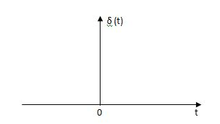
Fig. Unit Impulse Signal
The mathematical representations
A (t) = 0 for t ≠0
 dt = A e
Where A represent energy or area of the Laplace Transform of Impulse signal is
L [A (t)] = A
Unit Impulse Signal:
If A = 1
 (t) = 0 for t ≠0
L [ (t)] = 1
The transfer function of a linear time invariant
System is the Laplace transform of the impulse response of the system. If a unit impulse signal is applied to system then Laplace transform of the output c(s) is the transfer function G(s)
As we know G(s) = c(s)/R(S)
r(t) =  (t)
(t)
R(s) = L [ (t)] = 1
:. G(S) = C(s)
(b) Step signal:
Step signal of size A is a signal that change from zero level to A in zero time and stays there forever.
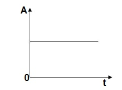
Fig. Unit Step Signal
r(t)= A t >=0
=0 t<0
L[r(t)] = R(s) = A/s
Unit Step Signal:
If the magnitude of the slip signal is I then it is called unit step signal.
u(t) = 1
t>=0
t<0
L[u(t)] = 1/s
(c) Ramp Signal:
The vamp signal increase linearly with time from initial value of zero at t= 0 as shown in fig is below
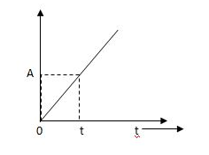
Fig. Ramp Signal
r(t) = At t>=0
=0 t<0
A is the slope of the line The Laplace transform of ramp signal is
L[r(t)] = R(s) = A/s2
(d) Parabolic Signal:
The instantaneous value of a parabolic signal varies as square of the time from an initial value of zero t=0. The signal representation in fig 14 below.
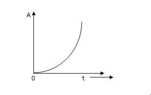
Fig. Parabolic Signal
r(t) At2 t>=0
=0 t<0
Then Laplace Transform is given as
R(s) = L[At2] = 2A/s3
If no error then E(t) =0, :. R(t) = c(t), output is tracking the input.
Steady state Errors signal (ess): - (t  )
)
Ess = t  e(t)
e(t)
Using final values, the theorem
 = ess =
  S.E (s)
ess=  S[R(s)/1+G/(s)]
Q10) For the CLTF G(s) =  . Find Kp, Kv and Ka?
A10)
Kp =  G(s)
G(s)
= 

= 1
Kv =  SG(s)
SG(s)
=  S
S 
= 0
Ka =  s2 G(s)
=  s2
s2 
= 0
Q11) For a unity feedback system G(s) =  an input t3u(t) is applied. Find the steady state error?
A11)
ess= 

r(t) = t3u(t)
R(s) = 6/s4
H(s) =1
ess= 

= 
= 
= 5/3
Q12) For the OLTF with unity feedback is G(s)=  . Determine the damping ratio, maximum overshoot, rise time?
A12)
The CLTF will be T(s) = 
T(s) = 
For second order system,
S2 + 2ξWnS + Wn2
wn =  = 5.1
= 5.1
2ξWn = 5
i) Damping Ratio  = 0.49
Ii) Maximum overshoot Mp = e-∏ξ / √1 –ξ2 x 100
= e-∏x0.49 / √1 –(0.49)2
= 17.1%
Iii) Rise Time tr = ∏ - φ/Wd
Wd = Wn√1 - ξ2
= 5.1 √1 – (0.49)2
= 4.45 sec
φ= tan-1√1 – ξ2 / ξ = 1.059 rad
tr = ∏ - φ/Wd
= ∏ - 1.059/4.45
=468.53msec
Q13) Define and derive the time domain specifications for a second order system?
A13)
1) Rise Time (tp)
The time taken by the output to reach the already status value for the first time is known as Rise time.
C(t) = 1-e- wnt/
wnt/ 1-
1- 2 sin (wdt+ø)
Sin (wd +ø) = 0
Wdt +ø = n
tr = n -ø/wd
-ø/wd
For first time so, n=1.
tr =  -ø/wd
-ø/wd
T=1/
2) Peak Time (tp)
The peak value attained by the output is called peak time. The time required by the output to reach this value is lp.
d(cct) /dt = 0 (maxima)
d(t)/dt = peak value
tp = n /wd for n=1
tp =  wd
wd
3) Peak Overshoot Value:
Maximum deviation of output from steady state value is called peak overshoot value (Mp).
(ltp) = 1 = Mp
( Sin(Wat + φ )
( Sin( Wd∏/Wd + φ)
Mp = e-∏ξ / √1 –ξ2
Condition 3 ξ = 1
C( S ) = R( S ) Wn2 / S2 + 2ξWnS + Wn2
C( S ) = Wn2 / S(S2 + 2WnS + Wn2) [ R(S) = 1/S ]
C( S ) = Wn2 / S( S2 + Wn2 )
C( t ) = 1 – e-Wnt + tWne-Wnt
The response is critically damped.
4) Settling Time (ts):
ts = 3 / ξWn ( 5% )
ts = 4 / ξWn ( 2% )
Q14) Determine the type and order of the system G(s)= K/S(S+1)
G(S)= K(S+1)/S2(S+2)
A14)
G(s)= K/S(S+1)
It is order 2 and type 1 system
G(S)= K(S+1)/S2(S+2)
It is order 3 and type 2 system
Q15) Derive position error coefficient?
A15)
R(s)= Unit step
R(t) = u(t)
R(s) = 1/s
Ess =  s[ R(s)/1+G(s)]
=  s[ys/1+G(s)]
ess=  1+1/1+G(s)
=1/1+lt G(s) s- 0
Kp =  G(s)
G(s)
(Position error coefficient)
Q16) What is sensitivity of a feedback system? Derive its expression?
A16)
The feedback systems are having many advantages over the non-feedback system as we have seen earlier. So, some performance parameters can be controlled through this feedback system such as sensitivity, noise etc. Sensitivity is a parameter which forecasts the effectiveness of feedback in reducing the influence of these variations on system performance. [Reference 4]
The output of the open loop system is given by
C(s) = G(s)R(s)
Now due to variation in parameters G(s) changes to [G(s)+ G(s)]. The output will now become
C(s)+ C(s) = [G(s)+
 G(s)] R(s)
 C(s) =
  G(s)R(s)
For closed loop system the output is given as
C(s) =  R(s)
R(s)
Now due to variation in parameters it becomes
C(s)+ C(s) =
 R(s)
R(s)
The above equation shows that if there is variation in parameters then G(s) is reduced by factor of 1+G(s)H(s). The variation in overall transfer function T(s) due to change in G(s) is defined as sensitivity.
Sensitivity = 
When there is small change in G(s) then sensitivity becomes

 : Sensitivity of T w.r.t G
For closed loop system the sensitivity will be
 =
=  x
x  =
= 
For open loop system
 = 1
= 1
As T=G
The sensitivity of T w.r.t H is given as
 =G [
=G [ ]
]  =
= 
The above equation shows that for large values of GH sensitivity of the feedback system w.r.t H approaches to unity.
Q17) What are the design consideration of Higher Order System?
A17)
The time domain analysis for second order system can be extended to third order system. Let transfer function for third order system be,
C(S)/R(S) = Wn2/(1 + ST)(S2 + 2ξWnS + Wn2)
Let 1/T = P
C(S)/R(S) = Wn2P/(S + P) (S2 + 2ξWnS + Wn2)
Taking Laplace inverse of above equation (for unit step response will be)
Cp(t) = 1 – K1e-pt + K2e-ξWntSin[ Wn√(1-ξ2)t - φ ]
Where K1 = Wn2 / Wn2 - 2ξWnp + p2
K2 = 1 / √1 – ξ2(1 - 2ξWn/p + Wn2/p2)
φ = tan-1√(1 – ξ2) / -ξ + tan-1Wn√1- ξ2/p – ξWn
From above equations we can conclude that:
(1). The system has three poles S = -p and S = - ξWn+-√(1 – ξ2). So the position of these poles effect the system. As the pole S = -p moves towards the origin, the output Cp(t) is dominated by only this pole.
(2). As the pole S = -p moves away from the origin, the response Cp(t) is dominated by the complex poles at S = -ξWn+-(√1-ξ2)jWn.
The response of third order system is shown in figure.
The relative location of dominant poles of the third order system is shown below in fig.
Q18) Explain the steady state and Transient response of a system?
A18)
The Response of the system as a function of time, to the applied excitation is called Time Response. The time response of a system can be fully studied by studying the following two responses

The total time response C(t) is given by
C(t) = Ctr(t) + Css(t)
Where Ctr(t) = transient response
Css(t) = steady state response
Consider the class of differential equation

Where the coefficient ai and bi are constant, u = u(t) (the input) is a known time function, and y = y(t) (the output) is the unknown solution of the equation. Generally, m ≤ n, and n is called the order of the differential equation.
The Free Response
The Free response of a differential equation is the solution of the differential equation when the input u(t) is identically zero. If the input u(t) is identically zero, then the differential equation has the form:

The solution y(t) of such an equation depends only on the initial conditions.
The Forced Response
The forced response yb(t) of a differential equation is the solution of the differential equation when all the initial conditions are identically zero.

The Total Response
The total response of a linear constant −coefficient differential equation is the sum of the free response and the forced response.
The Steady State and Transient Response
The steady state response and transient response are another pair of quantities whose sum is equal to the total response. These terms are often used for specifying control system performance. They are defined as follows. The steady state response is that part of the total response which does not approach zero as time approaches infinity. The transient response is that part of the total response which approaches zero as time approaches infinity
For stable system Transient response vanishes after some time to get final value closer to the desired value.
Steady State Response: The part of the time response which remains after complete transient response vanishes from the system output. The steady state response is generally the final value achieved by the system output. The difference between the desired output and the actual output of the system is called as Steady state error (ess) and the time taken to reach steady state is called Settling time.
Unit - 3
Time response of system
Q1) Find the initial value for the function f(t) = 2u(t)+3cost u(t)?
A1)
f(t) = 2u(t)+3cost u(t)
F(s) = 
SF(s) = 2+ 
By initial value theorem
 = f(0+)
 =
=  2+
2+  = 5 = f(0+)
Hence, initial value of the function is 5
Q2) Find final value of the function F(s) = 
A2)
F(s) = 
SF(s) = 
By final value theorem
 =
= 
 =
=  = 0.1
= 0.1
So, final value of the function is 0.1
Q3) The open loop transfer function of a system with unity feedback gain G( S ) = 20 / S2 + 5S + 4. Determine the ξ, Mp, tr, tp.
A3)
Finding closed loop transfer function,
C( S ) / R( S ) = G( S ) / 1 + G( S ) + H( S )
As it is unity feedback so, H(S) = 1
C(S)/R(S) = G(S)/1 + G(S)
= 20/S2 + 5S + 4/1 + 20/S2 + 5S + 4
C(S)/R(S) = 20/S2 + 5S + 24
Standard equation for second order system,
S2 + 2ξWnS + Wn2 = 0
We have,
S2 + 5S + 24 = 0
Wn2 = 24
Wn = 4.89 rad/sec
2ξWn = 5
(a). ξ = 5/2 x 4.89 = 0.511
(b). Mp% = e-∏ξ / √1 –ξ2 x 100
= e-∏ x 0.511 / √1 – (0.511)2 x 100
Mp% = 15.4%
(c). tr = ∏ - φ / Wd
φ = tan-1√1 – ξ2 / ξ
φ= tan-1√1 – (0.511)2 / (0.511)
φ = 1.03 rad.
tr = ∏ - 1.03/Wd
Wd = Wn√1 – ξ2
= 4.89 √1 – (0.511)2
Wd = 4.20 rad/sec
tr = ∏ - 1.03/4.20
tr = 502.34 msec
(d). tp = ∏/4.20 = 747.9 msec
Q4) A second order system has Wn = 5 rad/sec and is ξ = 0.7 subjected to unit step input. Find (i) closed loop transfer function. (ii) Peak time (iii) Rise time (iv) Settling time (v) Peak overshoot.
A4)
The closed loop transfer function is
C(S)/R(S) = Wn2 / S2 + 2ξWnS + Wn2
= (5)2 / S2 + 2 x 0.7 x S + (5)2
C(S)/R(S) = 25 / S2 + 7s + 25
(ii). tp = ∏ / Wd
Wd = Wn√1 - ξ2
= 5√1 – (0.7)2
= 3.571 sec
(iii). tr = ∏ - φ/Wd
φ= tan-1√1 – ξ2 / ξ = 0.795 rad
tr = ∏ - 0.795 / 3.571
tr = 0.657 sec
(iv). For 2% settling time
ts = 4 / ξWn = 4 / 0.7 x 5
ts = 1.143 sec
(v). Mp = e-∏ξ / √1 –ξ2 x 100
Mp = 4.59%
Q5) The open loop transfer function of a unity feedback control system is given by G(S) = K/S(1 + ST). Calculate the value by which k should be multiplied so that damping ratio is increased from 0.2 to 0.4?
A5)
C(S)/R(S) = G(S) / 1 + G(S)H(S) H(S) = 1
C(S)/R(S) = K/S(1 + ST) / 1 + K/S(1 + ST)
C(S)/R(S) = K/S(1 + ST) + K
C(S)/R(S) = K/T / S2 + S/T + K/T
For second order system,
S2 + 2ξWnS + Wn2
2ξWn = 1/T
ξ = 1/2WnT
Wn2 = K/T
Wn =√K/T
ξ = 1 / 2√K/T T
ξ = 1 / 2 √KT
Forξ1 = 0.2, for ξ2 = 0.4
ξ1 = 1 / 2 √K1T
ξ2 = 1 / 2 √K2T
ξ1/ ξ2 = √K2/K1
K2/K1 = (0.2/0.4)2
K2/K1 = 1 / 4
K1 = 4K2
Q6) Consider the transfer function C(S)/R(S) = Wn2 / S2 + 2ξWnS + Wn2. Find ξ, Wn so that the system responds to a step input with 5% overshoot and settling time of 4 sec?
A6)
Mp = 5% = 0.05
Mp = e-∏ξ / √1 –ξ2
0.05 = e-∏ξ / √1 –ξ2
Cn 0.05 = - ∏ξ / √1 –ξ2
-2.99 = - ∏ξ / √1 –ξ2
8.97(1 – ξ2) = ξ2∏2
0.91 – 0.91 ξ2 = ξ2
0.91 = 1.91 ξ2
ξ2 = 0.69
(ii). ts = 4/ ξWn
4 = 4/ ξWn
Wn = 1/ ξ = 1/ 0.69
Wn = 1.45 rad/sec
Q7) The block diagram of a system using PI controllers is shown in the figure below Calculate:
(a). The steady state without and with controller for unit step input?
(b). Determine TF of newly constructed sys. With controller so, that a CL Poles is located at -5?

A7)
(a). Without:
C(S)/R(S) = 0.2/(S + 1)
C(S) = R(S) 0.2/(S + 1) + 0.2
For unit step
Ess = 1/1 + Kp
Kp = lt G(S)
S 0
= lt 0.2/(S + 1)
S 0
Kp = 0.2
Ess = 1/1.2 = 5/6 = 0.8
(b). With controller:
Gc(S) = Kp + Ki/S
G’(S) = Gc(S).G(S)
= ( Kp + Ki/S )0.2/(S + 1)
= (KpS + Ki)0.2/S(S + 1)
Ess = 1/1 + Kp = 0
So, the value of ess is decreased.
(b). Given
Kpi/Kp = 0.1
G’(S) = (Kp + Ki/S)(0.2/S + 1)
= (KpS + Ki)0.2/S(S + 1)
As a pole is to be added so, we have to examine the CE,
1 + G’(S) = 0
1 + (Kp + Ki)0.2/S(S + 1) = 0
S2 + S + 0.2KpS + 0.2Ki = 0
S2 + (0.2Kp + 1)S + 0.2Ki = 0
Given,
Kpi = 0.1Ki
Kp = 10Ki
S2 + (2Ki + 1)S + 0.2Ki = 0
Pole at S = -5
25 + (2Ki + 1)(-5) + 0.2Ki = 0
-10Ki – 5 + 25 + 0.2Ki = 0
-9.8Ki = -20
Ki = 2.05
Kp = 10Ki
= 20.5
Now,
G’(S) = (KpS + Ki)(0.2)/S(S + 1)
= (20.5S + 2.05)(0.2)/S(S + 1)
G’(S) = 4.1S + 0.41/S(S + 1)
Q8) The block diagram of a system using Pd controller is shown, the PD is used to increase ξ to 0.8. Determine the T.F of controller?

A8)
(1). Kp = 1
Without controller:
C(S)/R(S) = 16/S2 + 1.6S + 16
wn = 4
2 ξwn = 16
ξ = 1.6/2 x 4 = 0.2
(b). With derivative:
ξS = 0.2 to 0.8
Undamped to critically damped,
G’(S) = (1 + KdS)(16)/(S2 + 1.6S)
CE:
S2 + 1.6S + 16(1 + KdS) = 0
S2 + (1.6 + Kd)S + 16 = 0
2 ξwn = 1.6 + Kd1.6
wn = 4
ξS = 0.8
2 x 4 x 0.8 = 1.6 + Kd1.6
6.4 – 1.6 = Kd1.6
4.8/16 = Kd
Kd = 0.3
TF = (1 + 0.3S)16/S(S + 16)
Q9) With help of waveform explain all the standard test signals?
A9)
The Impulse signal, Ramp signal, unit step and parabolic signals are used as the standard test signals. All these signals are explained below.
(a) Impulse Signal:
This signal has zero amplitude everywhere except at the origin. Fig below shown the representation of Impulse signal.
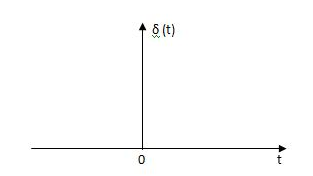
Fig. Unit Impulse Signal
The mathematical representations
A (t) = 0 for t ≠0
 dt = A e
Where A represent energy or area of the Laplace Transform of Impulse signal is
L [A (t)] = A
Unit Impulse Signal:
If A = 1
 (t) = 0 for t ≠0
L [ (t)] = 1
The transfer function of a linear time invariant
System is the Laplace transform of the impulse response of the system. If a unit impulse signal is applied to system then Laplace transform of the output c(s) is the transfer function G(s)
As we know G(s) = c(s)/R(S)
r(t) =  (t)
(t)
R(s) = L [ (t)] = 1
:. G(S) = C(s)
(b) Step signal:
Step signal of size A is a signal that change from zero level to A in zero time and stays there forever.

Fig. Unit Step Signal
r(t)= A t >=0
=0 t<0
L[r(t)] = R(s) = A/s
Unit Step Signal:
If the magnitude of the slip signal is I then it is called unit step signal.
u(t) = 1
t>=0
t<0
L[u(t)] = 1/s
(c) Ramp Signal:
The vamp signal increase linearly with time from initial value of zero at t= 0 as shown in fig is below
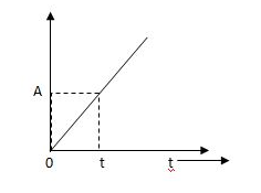
Fig. Ramp Signal
r(t) = At t>=0
=0 t<0
A is the slope of the line The Laplace transform of ramp signal is
L[r(t)] = R(s) = A/s2
(d) Parabolic Signal:
The instantaneous value of a parabolic signal varies as square of the time from an initial value of zero t=0. The signal representation in fig 14 below.
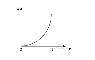
Fig. Parabolic Signal
r(t) At2 t>=0
=0 t<0
Then Laplace Transform is given as
R(s) = L[At2] = 2A/s3
If no error then E(t) =0, :. R(t) = c(t), output is tracking the input.
Steady state Errors signal (ess): - (t  )
)
Ess = t  e(t)
e(t)
Using final values, the theorem
 = ess =
  S.E (s)
ess=  S[R(s)/1+G/(s)]
Q10) For the CLTF G(s) =  . Find Kp, Kv and Ka?
A10)
Kp =  G(s)
G(s)
= 

= 1
Kv =  SG(s)
SG(s)
=  S
S 
= 0
Ka =  s2 G(s)
=  s2
s2 
= 0
Q11) For a unity feedback system G(s) =  an input t3u(t) is applied. Find the steady state error?
A11)
ess= 

r(t) = t3u(t)
R(s) = 6/s4
H(s) =1
ess= 

= 
= 
= 5/3
Q12) For the OLTF with unity feedback is G(s)=  . Determine the damping ratio, maximum overshoot, rise time?
A12)
The CLTF will be T(s) = 
T(s) = 
For second order system,
S2 + 2ξWnS + Wn2
wn =  = 5.1
= 5.1
2ξWn = 5
i) Damping Ratio  = 0.49
Ii) Maximum overshoot Mp = e-∏ξ / √1 –ξ2 x 100
= e-∏x0.49 / √1 –(0.49)2
= 17.1%
Iii) Rise Time tr = ∏ - φ/Wd
Wd = Wn√1 - ξ2
= 5.1 √1 – (0.49)2
= 4.45 sec
φ= tan-1√1 – ξ2 / ξ = 1.059 rad
tr = ∏ - φ/Wd
= ∏ - 1.059/4.45
=468.53msec
Q13) Define and derive the time domain specifications for a second order system?
A13)
1) Rise Time (tp)
The time taken by the output to reach the already status value for the first time is known as Rise time.
C(t) = 1-e- wnt/
wnt/ 1-
1- 2 sin (wdt+ø)
Sin (wd +ø) = 0
Wdt +ø = n
tr = n -ø/wd
-ø/wd
For first time so, n=1.
tr =  -ø/wd
-ø/wd
T=1/
2) Peak Time (tp)
The peak value attained by the output is called peak time. The time required by the output to reach this value is lp.
d(cct) /dt = 0 (maxima)
d(t)/dt = peak value
tp = n /wd for n=1
tp =  wd
wd
3) Peak Overshoot Value:
Maximum deviation of output from steady state value is called peak overshoot value (Mp).
(ltp) = 1 = Mp
( Sin(Wat + φ )
( Sin( Wd∏/Wd + φ)
Mp = e-∏ξ / √1 –ξ2
Condition 3 ξ = 1
C( S ) = R( S ) Wn2 / S2 + 2ξWnS + Wn2
C( S ) = Wn2 / S(S2 + 2WnS + Wn2) [ R(S) = 1/S ]
C( S ) = Wn2 / S( S2 + Wn2 )
C( t ) = 1 – e-Wnt + tWne-Wnt
The response is critically damped.
4) Settling Time (ts):
ts = 3 / ξWn ( 5% )
ts = 4 / ξWn ( 2% )
Q14) Determine the type and order of the system G(s)= K/S(S+1)
G(S)= K(S+1)/S2(S+2)
A14)
G(s)= K/S(S+1)
It is order 2 and type 1 system
G(S)= K(S+1)/S2(S+2)
It is order 3 and type 2 system
Q15) Derive position error coefficient?
A15)
R(s)= Unit step
R(t) = u(t)
R(s) = 1/s
Ess =  s[ R(s)/1+G(s)]
=  s[ys/1+G(s)]
ess=  1+1/1+G(s)
=1/1+lt G(s) s- 0
Kp =  G(s)
G(s)
(Position error coefficient)
Q16) What is sensitivity of a feedback system? Derive its expression?
A16)
The feedback systems are having many advantages over the non-feedback system as we have seen earlier. So, some performance parameters can be controlled through this feedback system such as sensitivity, noise etc. Sensitivity is a parameter which forecasts the effectiveness of feedback in reducing the influence of these variations on system performance. [Reference 4]
The output of the open loop system is given by
C(s) = G(s)R(s)
Now due to variation in parameters G(s) changes to [G(s)+ G(s)]. The output will now become
C(s)+ C(s) = [G(s)+
 G(s)] R(s)
 C(s) =
  G(s)R(s)
For closed loop system the output is given as
C(s) =  R(s)
R(s)
Now due to variation in parameters it becomes
C(s)+ C(s) =
 R(s)
R(s)
The above equation shows that if there is variation in parameters then G(s) is reduced by factor of 1+G(s)H(s). The variation in overall transfer function T(s) due to change in G(s) is defined as sensitivity.
Sensitivity = 
When there is small change in G(s) then sensitivity becomes

 : Sensitivity of T w.r.t G
For closed loop system the sensitivity will be
 =
=  x
x  =
= 
For open loop system
 = 1
= 1
As T=G
The sensitivity of T w.r.t H is given as
 =G [
=G [ ]
]  =
= 
The above equation shows that for large values of GH sensitivity of the feedback system w.r.t H approaches to unity.
Q17) What are the design consideration of Higher Order System?
A17)
The time domain analysis for second order system can be extended to third order system. Let transfer function for third order system be,
C(S)/R(S) = Wn2/(1 + ST)(S2 + 2ξWnS + Wn2)
Let 1/T = P
C(S)/R(S) = Wn2P/(S + P) (S2 + 2ξWnS + Wn2)
Taking Laplace inverse of above equation (for unit step response will be)
Cp(t) = 1 – K1e-pt + K2e-ξWntSin[ Wn√(1-ξ2)t - φ ]
Where K1 = Wn2 / Wn2 - 2ξWnp + p2
K2 = 1 / √1 – ξ2(1 - 2ξWn/p + Wn2/p2)
φ = tan-1√(1 – ξ2) / -ξ + tan-1Wn√1- ξ2/p – ξWn
From above equations we can conclude that:
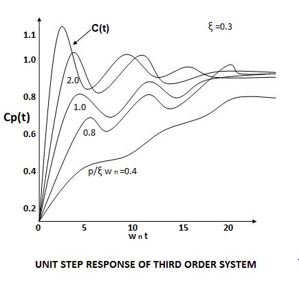
(1). The system has three poles S = -p and S = - ξWn+-√(1 – ξ2). So the position of these poles effect the system. As the pole S = -p moves towards the origin, the output Cp(t) is dominated by only this pole.
(2). As the pole S = -p moves away from the origin, the response Cp(t) is dominated by the complex poles at S = -ξWn+-(√1-ξ2)jWn.
The response of third order system is shown in figure.
The relative location of dominant poles of the third order system is shown below in fig.
Q18) Explain the steady state and Transient response of a system?
A18)
The Response of the system as a function of time, to the applied excitation is called Time Response. The time response of a system can be fully studied by studying the following two responses

The total time response C(t) is given by
C(t) = Ctr(t) + Css(t)
Where Ctr(t) = transient response
Css(t) = steady state response
Consider the class of differential equation

Where the coefficient ai and bi are constant, u = u(t) (the input) is a known time function, and y = y(t) (the output) is the unknown solution of the equation. Generally, m ≤ n, and n is called the order of the differential equation.
The Free Response
The Free response of a differential equation is the solution of the differential equation when the input u(t) is identically zero. If the input u(t) is identically zero, then the differential equation has the form:

The solution y(t) of such an equation depends only on the initial conditions.
The Forced Response
The forced response yb(t) of a differential equation is the solution of the differential equation when all the initial conditions are identically zero.

The Total Response
The total response of a linear constant −coefficient differential equation is the sum of the free response and the forced response.
The Steady State and Transient Response
The steady state response and transient response are another pair of quantities whose sum is equal to the total response. These terms are often used for specifying control system performance. They are defined as follows. The steady state response is that part of the total response which does not approach zero as time approaches infinity. The transient response is that part of the total response which approaches zero as time approaches infinity
For stable system Transient response vanishes after some time to get final value closer to the desired value.
Steady State Response: The part of the time response which remains after complete transient response vanishes from the system output. The steady state response is generally the final value achieved by the system output. The difference between the desired output and the actual output of the system is called as Steady state error (ess) and the time taken to reach steady state is called Settling time.