Unit - 6
State variable methods of analysis
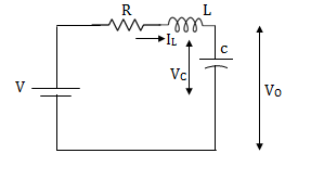
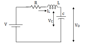
Q1) Obtatin the state space representation for the given electrical system
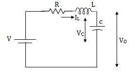
A1)
The state model is given as
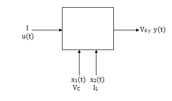
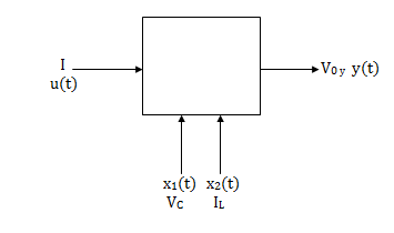
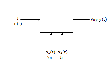
The state model shows that there are two energy storing elements L, C. As we already know that Number of state variables is equal to the number of energy storing elements.Hence we have two state variables[x1(t) and x2(t)]. We have one output V0(taken across capacitor) and input u(t).
The output equation is then given as
Y(t)=CX(t)+DU(t)
V0=Vc= x1(t) ….(a)
Hence output equation becomes
V0= x1(t)
y(t)=[1 0] +[0]u(t)
So, C=[1 0] D=[0]
Now writing the state equation
 =Ax(t)+Bu(t)
For that applying KVL in the above circuit
V=ILR+L +Vc
+Vc
State Equation is  =Ax(t)+Bu(t)
 =
=
x1(t)=Vc
 =
=
IL=C
 =
=
 =
= =
=
 =(1/C) x2(t) ……….(b)
 =
= =
=
VL=L
 =
= =VL/L
=VL/L
From KVL
L =VL=V-ILR-VC
 =
= =
=
 =
= …………….(c)
From equation (b) and (c)
 = [0 1/c]
 + [0 0]u(t)
 =[-1/L -R/L]
 + [1/L 0]
Now writing the state equation
 =Ax(t)+Bu(t)
 =
= +
+ 
Hence A= B=
B= 
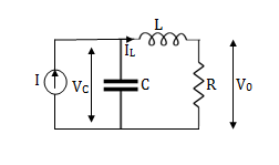
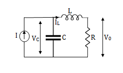
Q2) Obtatin the state space representation for the given electircal system
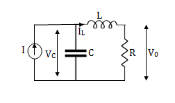
A2)
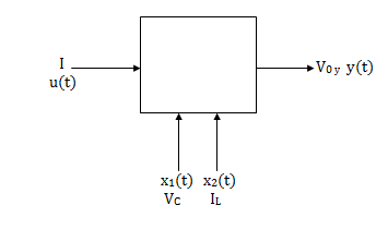
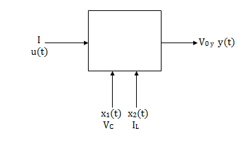
The state model shows that there are two energy storing elements L, C. As we already know that Number of state variables is equal to the number of energy storing elements.Hence we have two state variables[x1(t) and x2(t)]. We have one output V0(taken across capacitor) and input u(t).
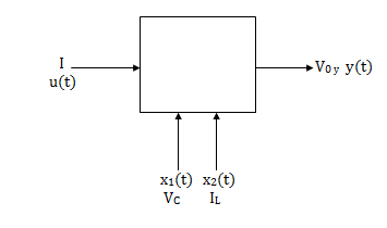
Here output is V0. But from above electrical circuit V0=ILR
V0=x2(t)R
y(t)= V0= [0 R]  + [0] u(t)
The output equation is given as
Y(t)=CX(t)+DU(t)
C=[0 R] D=[0]
Now finding state equation,we apply KCL in the given electrical circuit
I=IC+IL
 =
=
But I-IL=IC
 =
=
 =
=
 =
=
 =
= x2(t)+
 ……..(a)
 =[0 1/C]
 + [1/C 0]
 …….(b)
 =
= =
=
Applying KVL in the given electrical circuit we get
VC=VL+ILR
VC-ILR=VL=L

 =
=
 =[1/L -R/L]
  + [0] u(t) ………….(c)
From equation (b) and (c) we have
Now writing the state equation
 =Ax(t)+Bu(t)
 =
= +
+ 
Hence A= B=
B= 
Note: We should always take voltage across the inductor L, and current through capacitor C.
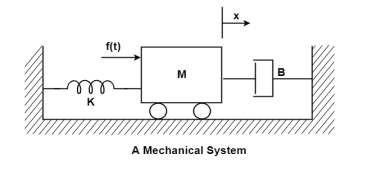
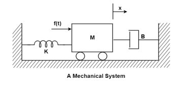
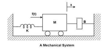
Q3) Write the state equation for the mechanical system shown below?
A3)
The free body diagram is

The position and velocity are state variables hence,
x1(t)=x(t)
x2(t)= 
 =
= =x2(t)
 =
=
The system equation will be

 =
=
 =
=
 =
=
The state equations are
 = x2(t)
 =
=
 =
= +
+ f(t)
f(t)
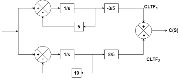
Q4) The closed loop transfer function is given as T(s)= . Calculate the state model?
A4)
The transfer function can be simplified using partial fraction method as
 =
=
S+2=As+10A+Bs+5B
Equating coefficients of s from both sides
A+B=1
Equating coefficients of s0 from both sides
10A+5B=2
Solving above equations we get
A=-3/5
B=8/5
The transfer function will be
T(s)=
=- +
+
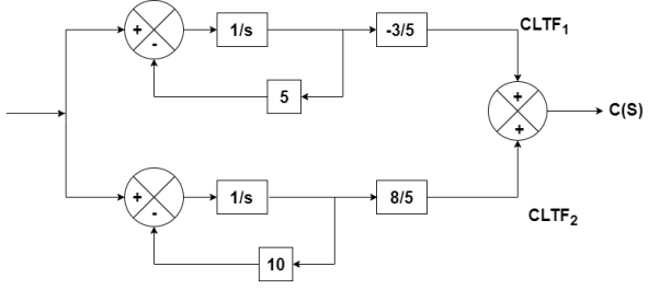
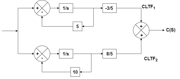
Number of poles= Number of energy storing elements
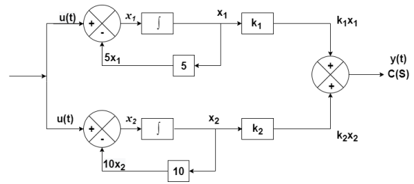
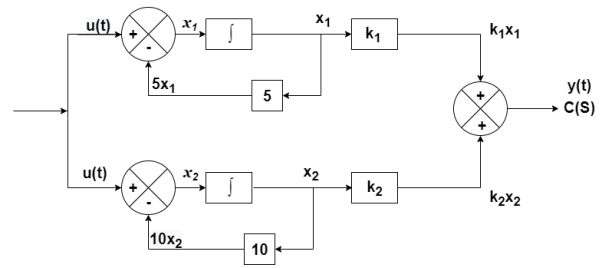
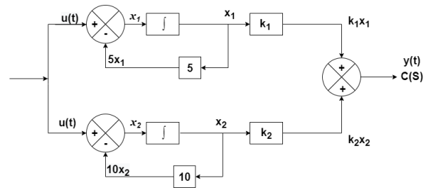
The output equation is given as
y(t)=k1x1(t)+k2x2(t)
y(t)= [k1 k2] + [0] [u(t)]
y(t)= [-3/5 8/5] + [0] [u(t)]
C=[-3/5 8/5]
D=0
From the above block diagram
 =u(t)-5 x1
 =-5x1+u(t)
 =-10x2+u
Therefore, the state equation is given as
 =
= +
+
A=
B=
Q5) The closed loop transfer function is given as T(s)= . Calculate the state model?
A5)
The transfer function can be simplified using partial fraction method as
 =
= +
+ 
s+7=A[s2+7s+12] +B[s2+6s+8] +C[s2+5s+6]
Equating coefficients of s2 from both sides
A+B+C=0
Equating coefficients of s from both sides
7A+6B+5C=1
Equating coefficients of s0 from both sides
12A+8B+6C=7
Solving above equations and finding values of A, B and C
A=5/2
B=-4
C=3/2
The transfer function will be
T(s)= +
+ 
= +
+ 
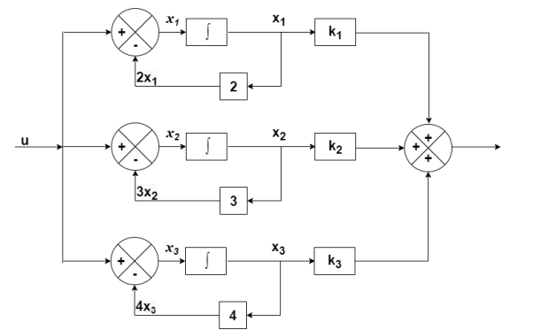
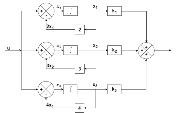
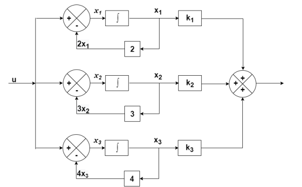
The output equation will be
y=k1x1+k2x2+k3x3
y=[k1 k2 k3] [5/2 -4 3/2]
C=[5/2 -4 3/2]
D=[0]
The state equation is given as
 =u(t)-2x1
 =-2x1+u(t)
 =-3x2+u
 = -4x3+u
Therefore
 =
= +
+ [u]
[u]
A=
B=
Q6) The closed loop transfer function is T(s)= . Find the state equation?
A6)
Here the number of poles = number of zeros
T(s)=
=
=
=2+ 
=2+
Solving above by partial fraction method
88= As+2A+Bs+3B
A=-B
2A+3B=88
A=-88
B=88
The transfer function becomes
T(s)= 2-
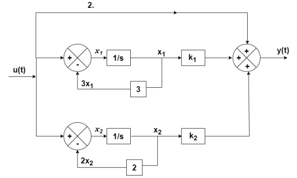
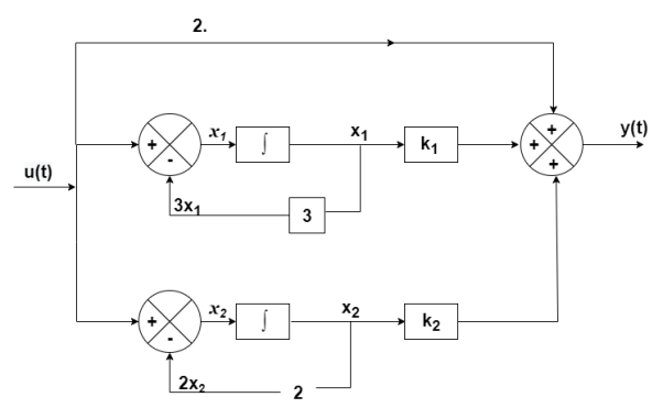
The output equation will be
y(t)=2U+k1x1+k2x2
y=[-88 88] +[2]u
+[2]u
The output equation will be
 =u(t)-3 x1
 =-3x1+u(t)
 =-2x2+u(t)
Therefore, the state equation is given as
 =
= +
+
A=
B=
Q7) The CLTF T(s)= . Find the state equation?
A7)
T(s)=
=
P1=2/s
P2=-8/s2
L1=-10/s
L2=-100/s2
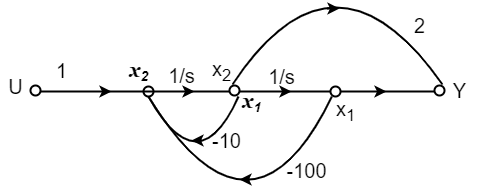
The state equation will be
 =x2
=x2
 =-10x2-100x1+u
 =
= +
+
Q8) Find the state equation from the given differential equation

A8)
Let y=x1
 =
= =x2
=x2
 =
= =x3
=x3
 =
=
The above differential equation than becomes
 +6
+6 +11 x2+6 x1=u
 (t) =u-6
 (t)-11 x2-6 x1
Hence the state equation will be
 =
=  +
+ [u]
[u]
Q9) For the given data below compute the transfer function of the system
A= B=
B= C=[1 0] and D=[0]
A9)
The state equation will be
 =
= +
+
 =x1
=x1
 =-6x1-5x2
Equation (14) in section 4.1
 = C{[SI-A]-1B} + D
=C{ -
- }-1B+D
=C B+D
B+D
=[1 0] 
 + 0
+ 0
= +0
+0
 =
=
Q10) Obtain the state space representation of following mechanical system

A10)
The position and velocity state variables will be
x1=y1
x2=
x3=y2
x4=
The difference equation will be
M1 +B1
+B1 +K1y1+B2(
 -
- +K2(y1-y2)=0
M2 + K2(y2-y1) + B2(
 -
- )=u
)=u
Writing above equations in the form of state variables
M2 =u-K2(y2-y1) +-B2(
 -
- )
)
M1 =- B1
=- B1 -K1y1-B2(
 -
- -K2(y1-y2)
 = -(
= -( +
+ )x1- (
 ) x2+(
 )x3+
)x3+ x4
x4
 =
=  x1+
x1+ x2-
x2- x3-
x3- x4+
x4+
Now writing all the state equations
 =x2
=x2
 = -(
= -( +
+ )x1- (
 ) x2+(
 )x3+
)x3+ x4
x4
 = x4
= x4
 =
=  x1+
x1+ x2-
x2- x3-
x3- x4+
x4+
The matrix form for above equations is given below
 =
= 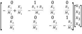 +
+ v(t)
v(t)
Q11) Obtain the eigenvectors of matrix A = 
A11)
For eigen values | iI-A|=0
| I-A|=
I-A|= -
-  =0
=0
| I-A| =
  =0
=0
| I-A| = (
 +4)2-1=0
| I-A| =
 2+8
2+8 +15=0
+15=0
The eigen values are
 1=-3,
1=-3,  2=-5
2=-5
Q12) Obtain the eigenvalues of system described as  =
= +
+ [u] and y= [1 0 0]
A12)
For eigenvalues | iI-A|=0
| I-A|=
I-A|= -
-  =0
=0
| I-A| =
  =0
=0
 3+6
3+6 2+11
2+11 +6=0
+6=0
( +1) (
+1) ( +2) (
+2) ( +3) = 0
Hence eigen values are  1=-1,
1=-1,  2=-2,
2=-2,  3= -3
3= -3
Q13) Find eigen vectors for the following system  =
=  +
+ [u] and y= [1 0 0]
A13)
Refer above que 12. The eigen values are  1=-1,
1=-1,  2=-2,
2=-2,  3= -3
3= -3
The eigen vectors will be
For  1=-1
1=-1
| I-A|X = 0
 = 0
= 0
-x1-x2 = 0
3x1 + x2 + 2x3 = 0
12x1+7x2+5x3=0
Solving above equations we get x1 = 1, x2= -1 as x3 = -1
Therefore, the eigen vectors are 
For  2=-2
2=-2
| I-A|X = 0
 = 0
= 0
-2x1-x2 = 0
3x1 + 2x2 + 3x3 = 0
17x1+7x2+4x3=0
Solving above equations we get x1 = 2, x2= -4 as x3 = -1
Therefore, the eigen vectors are 
For  3=-3
3=-3
| I-A|X = 0
 = 0
= 0
3x1+x2 = 0
3x1 + 3x2 + 2x3 = 0
12x1+7x2+3x3=0
Solving above equations we get x1 = 1, x2= -3 as x3 = 3
Therefore, the eigen vectors are 
Q14) Find the eigen vectors of the matrix A= 
A14)
For eigen values | iI-A|=0
| I-A|=
I-A|= -
-  =0
=0
| I-A| =
  =0
=0
| I-A| = (
 +3)2-1=0
| I-A| =
 2+6
2+6 +8=0
+8=0
 1=-2,
1=-2,  2=-4
2=-4
For  1=-2 the eigenvectors are
 -
-  x Xi=0
 -
-  x
x  = 0
= 0

 = 0
= 0
-x1+x2=0
For x1=1 x2=1 the equation above is satisfied.
Xi=
For  2=-4
2=-4
 -
-  x
x  = 0
= 0

 = 0
= 0
-x1-x2=0
For x1=1 x2= -1 the equation above is satisfied.
Xi=
Q15) Find the eigen vectors for the given matrix A=
A15)
For eigen values
| I-A|=
I-A|= -
-  =0
=0
| I-A| =
  =0
=0
| I-A| = (
 -3)(
-3)( -2)-2=0
| I-A| =
 2-5
2-5 +4=0
+4=0
 1=1,
1=1,  2=4
2=4
For  1=1 the eigenvectors are
 -
-  x Xi=0
 -
-  x
x  = 0
= 0

 = 0
= 0
-2x1+2x2=0
For x1=1 x2=1 the equation above is satisfied.
X1=
For  2=4
2=4
 -
-  x
x  = 0
= 0

 = 0
= 0
x1+2x2=0
For x1=2 x2= -1 the equation above is satisfied.
X2=
Arrange eigenvectors in a matrix P = 
P-1= -  =
=
The transformation matrix  =P-1AP
=
=
=
Q16) A system is represented by the state equation and output equation as
 =
=  +
+ u(t) and Y=[1 2]
Find the poles of the system and comment on stability?
A16)
A= 
The characteristic equation is given as
| I-A|=
I-A|= -
-  =0
=0
| I-A| =
  =0
=0
| I-A| = (
 +3) (
+3) ( +2)-2=0
| I-A| =
 2+5
2+5 +4=0
+4=0
 1=-1,
1=-1,  2=-4
2=-4
The poles are -1 and -4. Both on left half of s-plane so system is stable.
Q17) The state and output equation of LTI system is  =
=  +
+ [u] and y= [1 1 0]
 . Find the characteristic equation.
A17)
The characteristic equation is given as | I-A|=0
| I-A|=
I-A|= -
-  =0
=0
| I-A| =
  =0
=0
The characteristic equation is
 3-5
3-5 2-8
2-8 +2=0
+2=0
Hence poles are  1=-1,
1=-1,  2=-2,
2=-2,  3= -3
3= -3
Q18) A system is described by  =
= B=
B= C=[1 0] . Y = [1 0]. Check the controllability of the system?
A18)
[s] =[B AB]
= 
 ≠ 0 hence system is controllable.
Q19) A system is described by  =
= B=
B= C=[1 0] . Y = [1 0]. Check the observability of the system?
A19)
AT=  CT=
CT=
[Q]=[CT ATCT]
=

=

=
=0
 =0 hence not observable.
Q20) The state equation of the system is given below  =
= 
 +
+  u(t) . Y = [1 2]
 Comment on controllability?
A20)
A=  B=
B= 
Order of matrix n=2
[S] = [B AB]
=

= 
|S|= 0. Hence, system is not controllable.
Q21) The state space representation of a second order  = -x1+u and
  = x1-2x2+u. State whether the system is controllable or not?
A21)
 =
= 
 +
+  u(t)
u(t)
Order of matrix is n=2
[S] = [B AB]
=

= 
|S|= 0. Hence, system is not controllable.
Q22) A linear second order single input continuous time system is described as  = -2x1(t)+4x2(t) and
  = 2x1(t)-x2(t)+u(t). Comment on controllability?
A22)
 =
= 
 +
+  u(t)
u(t)
Order of matrix is n=2
[S] = [B AB]
=

= 
 ≠ 0 hence system is controllable.
Q23) What is the effect of pole zero cancellation on the controllability and observability of the system?
A23)
For an nth order system with distinct eigenvalues the transfer function be
T(s)= =[b0sm+b1sm-1+….+bm-1s+bm/[sn+a1sn-1+……..+an-1s+an]
=K(s- 1)( s-
 2)…….( s-
 m)/(s-
 1)( s-
 2)……( s-
 n)
n)
= 
ck are residue poles at s=
If the transfer function has identical pair of poles and zeros at  i=
i=  i
i
The effect of this cancellation of pole and zero on observability and controllability depends on the property of state variable.
- If the state variable is of the form below , then ci=0 will appear in control vector B and the state is uncontrollable.
 =
= 
 +
+  u
u
y=[1 1 1……..1] +b0u
+b0u
- On the other-hand if the state variables are of the form
 =
=  +
+
y=[c1 c2 c3…….. cn] +b0u
+b0u
Then then ci=0 will appear in output vector C and the state is shielded from observations.
- In LTI system if it has pole zero cancellation, the system will either be not controllable nor observable. But if the transfer function does not have any pole zero cancellations than the system can be represented by completely controllable and observable state model.
Unit - 6
State variable methods of analysis
Q1) Obtatin the state space representation for the given electrical system
A1)
The state model is given as
The state model shows that there are two energy storing elements L, C. As we already know that Number of state variables is equal to the number of energy storing elements.Hence we have two state variables[x1(t) and x2(t)]. We have one output V0(taken across capacitor) and input u(t).
The output equation is then given as
Y(t)=CX(t)+DU(t)
V0=Vc= x1(t) ….(a)
Hence output equation becomes
V0= x1(t)
y(t)=[1 0] +[0]u(t)
So, C=[1 0] D=[0]
Now writing the state equation
 =Ax(t)+Bu(t)
For that applying KVL in the above circuit
V=ILR+L +Vc
+Vc
State Equation is  =Ax(t)+Bu(t)
 =
=
x1(t)=Vc
 =
=
IL=C
 =
=
 =
= =
=
 =(1/C) x2(t) ……….(b)
 =
= =
=
VL=L
 =
= =VL/L
=VL/L
From KVL
L =VL=V-ILR-VC
 =
= =
=
 =
= …………….(c)
From equation (b) and (c)
 = [0 1/c]
 + [0 0]u(t)
 =[-1/L -R/L]
 + [1/L 0]
Now writing the state equation
 =Ax(t)+Bu(t)
 =
= +
+ 
Hence A= B=
B= 
Q2) Obtatin the state space representation for the given electircal system
A2)
The state model shows that there are two energy storing elements L, C. As we already know that Number of state variables is equal to the number of energy storing elements.Hence we have two state variables[x1(t) and x2(t)]. We have one output V0(taken across capacitor) and input u(t).
Here output is V0. But from above electrical circuit V0=ILR
V0=x2(t)R
y(t)= V0= [0 R]  + [0] u(t)
The output equation is given as
Y(t)=CX(t)+DU(t)
C=[0 R] D=[0]
Now finding state equation,we apply KCL in the given electrical circuit
I=IC+IL
 =
=
But I-IL=IC
 =
=
 =
=
 =
=
 =
= x2(t)+
 ……..(a)
 =[0 1/C]
 + [1/C 0]
 …….(b)
 =
= =
=
Applying KVL in the given electrical circuit we get
VC=VL+ILR
VC-ILR=VL=L

 =
=
 =[1/L -R/L]
  + [0] u(t) ………….(c)
From equation (b) and (c) we have
Now writing the state equation
 =Ax(t)+Bu(t)
 =
= +
+ 
Hence A= B=
B= 
Note: We should always take voltage across the inductor L, and current through capacitor C.
Q3) Write the state equation for the mechanical system shown below?
A3)
The free body diagram is

The position and velocity are state variables hence,
x1(t)=x(t)
x2(t)= 
 =
= =x2(t)
 =
=
The system equation will be

 =
=
 =
=
 =
=
The state equations are
 = x2(t)
 =
=
 =
= +
+ f(t)
f(t)
Q4) The closed loop transfer function is given as T(s)= . Calculate the state model?
A4)
The transfer function can be simplified using partial fraction method as
 =
=
S+2=As+10A+Bs+5B
Equating coefficients of s from both sides
A+B=1
Equating coefficients of s0 from both sides
10A+5B=2
Solving above equations we get
A=-3/5
B=8/5
The transfer function will be
T(s)=
=- +
+
Number of poles= Number of energy storing elements
The output equation is given as
y(t)=k1x1(t)+k2x2(t)
y(t)= [k1 k2] + [0] [u(t)]
y(t)= [-3/5 8/5] + [0] [u(t)]
C=[-3/5 8/5]
D=0
From the above block diagram
 =u(t)-5 x1
 =-5x1+u(t)
 =-10x2+u
Therefore, the state equation is given as
 =
= +
+
A=
B=
Q5) The closed loop transfer function is given as T(s)= . Calculate the state model?
A5)
The transfer function can be simplified using partial fraction method as
 =
= +
+ 
s+7=A[s2+7s+12] +B[s2+6s+8] +C[s2+5s+6]
Equating coefficients of s2 from both sides
A+B+C=0
Equating coefficients of s from both sides
7A+6B+5C=1
Equating coefficients of s0 from both sides
12A+8B+6C=7
Solving above equations and finding values of A, B and C
A=5/2
B=-4
C=3/2
The transfer function will be
T(s)= +
+ 
= +
+ 
The output equation will be
y=k1x1+k2x2+k3x3
y=[k1 k2 k3] [5/2 -4 3/2]
C=[5/2 -4 3/2]
D=[0]
The state equation is given as
 =u(t)-2x1
 =-2x1+u(t)
 =-3x2+u
 = -4x3+u
Therefore
 =
= +
+ [u]
[u]
A=
B=
Q6) The closed loop transfer function is T(s)= . Find the state equation?
A6)
Here the number of poles = number of zeros
T(s)=
=
=
=2+ 
=2+
Solving above by partial fraction method
88= As+2A+Bs+3B
A=-B
2A+3B=88
A=-88
B=88
The transfer function becomes
T(s)= 2-
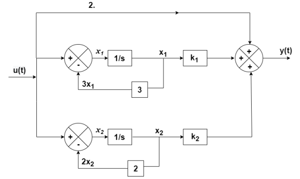
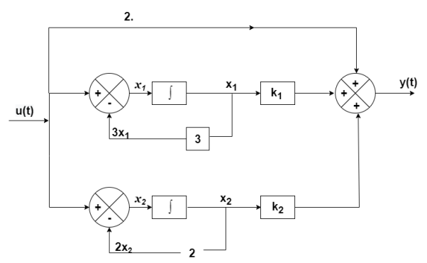
The output equation will be
y(t)=2U+k1x1+k2x2
y=[-88 88] +[2]u
+[2]u
The output equation will be
 =u(t)-3 x1
 =-3x1+u(t)
 =-2x2+u(t)
Therefore, the state equation is given as
 =
= +
+
A=
B=
Q7) The CLTF T(s)= . Find the state equation?
A7)
T(s)=
=
P1=2/s
P2=-8/s2
L1=-10/s
L2=-100/s2
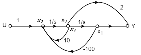
The state equation will be
 =x2
=x2
 =-10x2-100x1+u
 =
= +
+
Q8) Find the state equation from the given differential equation

A8)
Let y=x1
 =
= =x2
=x2
 =
= =x3
=x3
 =
=
The above differential equation than becomes
 +6
+6 +11 x2+6 x1=u
 (t) =u-6
 (t)-11 x2-6 x1
Hence the state equation will be
 =
=  +
+ [u]
[u]
Q9) For the given data below compute the transfer function of the system
A= B=
B= C=[1 0] and D=[0]
A9)
The state equation will be
 =
= +
+
 =x1
=x1
 =-6x1-5x2
Equation (14) in section 4.1
 = C{[SI-A]-1B} + D
=C{ -
- }-1B+D
=C B+D
B+D
=[1 0] 
 + 0
+ 0
= +0
+0
 =
=
Q10) Obtain the state space representation of following mechanical system

A10)
The position and velocity state variables will be
x1=y1
x2=
x3=y2
x4=
The difference equation will be
M1 +B1
+B1 +K1y1+B2(
 -
- +K2(y1-y2)=0
M2 + K2(y2-y1) + B2(
 -
- )=u
)=u
Writing above equations in the form of state variables
M2 =u-K2(y2-y1) +-B2(
 -
- )
)
M1 =- B1
=- B1 -K1y1-B2(
 -
- -K2(y1-y2)
 = -(
= -( +
+ )x1- (
 ) x2+(
 )x3+
)x3+ x4
x4
 =
=  x1+
x1+ x2-
x2- x3-
x3- x4+
x4+
Now writing all the state equations
 =x2
=x2
 = -(
= -( +
+ )x1- (
 ) x2+(
 )x3+
)x3+ x4
x4
 = x4
= x4
 =
=  x1+
x1+ x2-
x2- x3-
x3- x4+
x4+
The matrix form for above equations is given below
 =
= 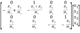 +
+ v(t)
v(t)
Q11) Obtain the eigenvectors of matrix A = 
A11)
For eigen values | iI-A|=0
| I-A|=
I-A|= -
-  =0
=0
| I-A| =
  =0
=0
| I-A| = (
 +4)2-1=0
| I-A| =
 2+8
2+8 +15=0
+15=0
The eigen values are
 1=-3,
1=-3,  2=-5
2=-5
Q12) Obtain the eigenvalues of system described as  =
= +
+ [u] and y= [1 0 0]
A12)
For eigenvalues | iI-A|=0
| I-A|=
I-A|= -
-  =0
=0
| I-A| =
  =0
=0
 3+6
3+6 2+11
2+11 +6=0
+6=0
( +1) (
+1) ( +2) (
+2) ( +3) = 0
Hence eigen values are  1=-1,
1=-1,  2=-2,
2=-2,  3= -3
3= -3
Q13) Find eigen vectors for the following system  =
=  +
+ [u] and y= [1 0 0]
A13)
Refer above que 12. The eigen values are  1=-1,
1=-1,  2=-2,
2=-2,  3= -3
3= -3
The eigen vectors will be
For  1=-1
1=-1
| I-A|X = 0
 = 0
= 0
-x1-x2 = 0
3x1 + x2 + 2x3 = 0
12x1+7x2+5x3=0
Solving above equations we get x1 = 1, x2= -1 as x3 = -1
Therefore, the eigen vectors are 
For  2=-2
2=-2
| I-A|X = 0
 = 0
= 0
-2x1-x2 = 0
3x1 + 2x2 + 3x3 = 0
17x1+7x2+4x3=0
Solving above equations we get x1 = 2, x2= -4 as x3 = -1
Therefore, the eigen vectors are 
For  3=-3
3=-3
| I-A|X = 0
 = 0
= 0
3x1+x2 = 0
3x1 + 3x2 + 2x3 = 0
12x1+7x2+3x3=0
Solving above equations we get x1 = 1, x2= -3 as x3 = 3
Therefore, the eigen vectors are 
Q14) Find the eigen vectors of the matrix A= 
A14)
For eigen values | iI-A|=0
| I-A|=
I-A|= -
-  =0
=0
| I-A| =
  =0
=0
| I-A| = (
 +3)2-1=0
| I-A| =
 2+6
2+6 +8=0
+8=0
 1=-2,
1=-2,  2=-4
2=-4
For  1=-2 the eigenvectors are
 -
-  x Xi=0
 -
-  x
x  = 0
= 0

 = 0
= 0
-x1+x2=0
For x1=1 x2=1 the equation above is satisfied.
Xi=
For  2=-4
2=-4
 -
-  x
x  = 0
= 0

 = 0
= 0
-x1-x2=0
For x1=1 x2= -1 the equation above is satisfied.
Xi=
Q15) Find the eigen vectors for the given matrix A=
A15)
For eigen values
| I-A|=
I-A|= -
-  =0
=0
| I-A| =
  =0
=0
| I-A| = (
 -3)(
-3)( -2)-2=0
| I-A| =
 2-5
2-5 +4=0
+4=0
 1=1,
1=1,  2=4
2=4
For  1=1 the eigenvectors are
 -
-  x Xi=0
 -
-  x
x  = 0
= 0

 = 0
= 0
-2x1+2x2=0
For x1=1 x2=1 the equation above is satisfied.
X1=
For  2=4
2=4
 -
-  x
x  = 0
= 0

 = 0
= 0
x1+2x2=0
For x1=2 x2= -1 the equation above is satisfied.
X2=
Arrange eigenvectors in a matrix P = 
P-1= -  =
=
The transformation matrix  =P-1AP
=
=
=
Q16) A system is represented by the state equation and output equation as
 =
=  +
+ u(t) and Y=[1 2]
Find the poles of the system and comment on stability?
A16)
A= 
The characteristic equation is given as
| I-A|=
I-A|= -
-  =0
=0
| I-A| =
  =0
=0
| I-A| = (
 +3) (
+3) ( +2)-2=0
| I-A| =
 2+5
2+5 +4=0
+4=0
 1=-1,
1=-1,  2=-4
2=-4
The poles are -1 and -4. Both on left half of s-plane so system is stable.
Q17) The state and output equation of LTI system is  =
=  +
+ [u] and y= [1 1 0]
 . Find the characteristic equation.
A17)
The characteristic equation is given as | I-A|=0
| I-A|=
I-A|= -
-  =0
=0
| I-A| =
  =0
=0
The characteristic equation is
 3-5
3-5 2-8
2-8 +2=0
+2=0
Hence poles are  1=-1,
1=-1,  2=-2,
2=-2,  3= -3
3= -3
Q18) A system is described by  =
= B=
B= C=[1 0] . Y = [1 0]. Check the controllability of the system?
A18)
[s] =[B AB]
= 
 ≠ 0 hence system is controllable.
Q19) A system is described by  =
= B=
B= C=[1 0] . Y = [1 0]. Check the observability of the system?
A19)
AT=  CT=
CT=
[Q]=[CT ATCT]
=

=

=
=0
 =0 hence not observable.
Q20) The state equation of the system is given below  =
= 
 +
+  u(t) . Y = [1 2]
 Comment on controllability?
A20)
A=  B=
B= 
Order of matrix n=2
[S] = [B AB]
=

= 
|S|= 0. Hence, system is not controllable.
Q21) The state space representation of a second order  = -x1+u and
  = x1-2x2+u. State whether the system is controllable or not?
A21)
 =
= 
 +
+  u(t)
u(t)
Order of matrix is n=2
[S] = [B AB]
=

= 
|S|= 0. Hence, system is not controllable.
Q22) A linear second order single input continuous time system is described as  = -2x1(t)+4x2(t) and
  = 2x1(t)-x2(t)+u(t). Comment on controllability?
A22)
 =
= 
 +
+  u(t)
u(t)
Order of matrix is n=2
[S] = [B AB]
=

= 
 ≠ 0 hence system is controllable.
Q23) What is the effect of pole zero cancellation on the controllability and observability of the system?
A23)
For an nth order system with distinct eigenvalues the transfer function be
T(s)= =[b0sm+b1sm-1+….+bm-1s+bm/[sn+a1sn-1+……..+an-1s+an]
=K(s- 1)( s-
 2)…….( s-
 m)/(s-
 1)( s-
 2)……( s-
 n)
n)
= 
ck are residue poles at s=
If the transfer function has identical pair of poles and zeros at  i=
i=  i
i
The effect of this cancellation of pole and zero on observability and controllability depends on the property of state variable.
- If the state variable is of the form below , then ci=0 will appear in control vector B and the state is uncontrollable.
 =
= 
 +
+  u
u
y=[1 1 1……..1] +b0u
+b0u
- On the other-hand if the state variables are of the form
 =
=  +
+
y=[c1 c2 c3…….. cn] +b0u
+b0u
Then then ci=0 will appear in output vector C and the state is shielded from observations.
- In LTI system if it has pole zero cancellation, the system will either be not controllable nor observable. But if the transfer function does not have any pole zero cancellations than the system can be represented by completely controllable and observable state model.
Unit - 6
State variable methods of analysis
Q1) Obtatin the state space representation for the given electrical system
A1)
The state model is given as
The state model shows that there are two energy storing elements L, C. As we already know that Number of state variables is equal to the number of energy storing elements.Hence we have two state variables[x1(t) and x2(t)]. We have one output V0(taken across capacitor) and input u(t).
The output equation is then given as
Y(t)=CX(t)+DU(t)
V0=Vc= x1(t) ….(a)
Hence output equation becomes
V0= x1(t)
y(t)=[1 0] +[0]u(t)
So, C=[1 0] D=[0]
Now writing the state equation
 =Ax(t)+Bu(t)
For that applying KVL in the above circuit
V=ILR+L +Vc
+Vc
State Equation is  =Ax(t)+Bu(t)
 =
=
x1(t)=Vc
 =
=
IL=C
 =
=
 =
= =
=
 =(1/C) x2(t) ……….(b)
 =
= =
=
VL=L
 =
= =VL/L
=VL/L
From KVL
L =VL=V-ILR-VC
 =
= =
=
 =
= …………….(c)
From equation (b) and (c)
 = [0 1/c]
 + [0 0]u(t)
 =[-1/L -R/L]
 + [1/L 0]
Now writing the state equation
 =Ax(t)+Bu(t)
 =
= +
+ 
Hence A= B=
B= 
Q2) Obtatin the state space representation for the given electircal system
A2)
The state model shows that there are two energy storing elements L, C. As we already know that Number of state variables is equal to the number of energy storing elements.Hence we have two state variables[x1(t) and x2(t)]. We have one output V0(taken across capacitor) and input u(t).
Here output is V0. But from above electrical circuit V0=ILR
V0=x2(t)R
y(t)= V0= [0 R]  + [0] u(t)
The output equation is given as
Y(t)=CX(t)+DU(t)
C=[0 R] D=[0]
Now finding state equation,we apply KCL in the given electrical circuit
I=IC+IL
 =
=
But I-IL=IC
 =
=
 =
=
 =
=
 =
= x2(t)+
 ……..(a)
 =[0 1/C]
 + [1/C 0]
 …….(b)
 =
= =
=
Applying KVL in the given electrical circuit we get
VC=VL+ILR
VC-ILR=VL=L

 =
=
 =[1/L -R/L]
  + [0] u(t) ………….(c)
From equation (b) and (c) we have
Now writing the state equation
 =Ax(t)+Bu(t)
 =
= +
+ 
Hence A= B=
B= 
Note: We should always take voltage across the inductor L, and current through capacitor C.
Q3) Write the state equation for the mechanical system shown below?
A3)
The free body diagram is

The position and velocity are state variables hence,
x1(t)=x(t)
x2(t)= 
 =
= =x2(t)
 =
=
The system equation will be

 =
=
 =
=
 =
=
The state equations are
 = x2(t)
 =
=
 =
= +
+ f(t)
f(t)
Q4) The closed loop transfer function is given as T(s)= . Calculate the state model?
A4)
The transfer function can be simplified using partial fraction method as
 =
=
S+2=As+10A+Bs+5B
Equating coefficients of s from both sides
A+B=1
Equating coefficients of s0 from both sides
10A+5B=2
Solving above equations we get
A=-3/5
B=8/5
The transfer function will be
T(s)=
=- +
+
Number of poles= Number of energy storing elements
The output equation is given as
y(t)=k1x1(t)+k2x2(t)
y(t)= [k1 k2] + [0] [u(t)]
y(t)= [-3/5 8/5] + [0] [u(t)]
C=[-3/5 8/5]
D=0
From the above block diagram
 =u(t)-5 x1
 =-5x1+u(t)
 =-10x2+u
Therefore, the state equation is given as
 =
= +
+
A=
B=
Q5) The closed loop transfer function is given as T(s)= . Calculate the state model?
A5)
The transfer function can be simplified using partial fraction method as
 =
= +
+ 
s+7=A[s2+7s+12] +B[s2+6s+8] +C[s2+5s+6]
Equating coefficients of s2 from both sides
A+B+C=0
Equating coefficients of s from both sides
7A+6B+5C=1
Equating coefficients of s0 from both sides
12A+8B+6C=7
Solving above equations and finding values of A, B and C
A=5/2
B=-4
C=3/2
The transfer function will be
T(s)= +
+ 
= +
+ 
The output equation will be
y=k1x1+k2x2+k3x3
y=[k1 k2 k3] [5/2 -4 3/2]
C=[5/2 -4 3/2]
D=[0]
The state equation is given as
 =u(t)-2x1
 =-2x1+u(t)
 =-3x2+u
 = -4x3+u
Therefore
 =
= +
+ [u]
[u]
A=
B=
Q6) The closed loop transfer function is T(s)= . Find the state equation?
A6)
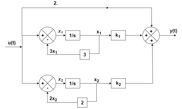
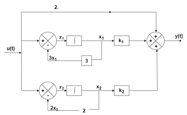
Here the number of poles = number of zeros
T(s)=
=
=
=2+ 
=2+
Solving above by partial fraction method
88= As+2A+Bs+3B
A=-B
2A+3B=88
A=-88
B=88
The transfer function becomes
T(s)= 2-
The output equation will be
y(t)=2U+k1x1+k2x2
y=[-88 88] +[2]u
+[2]u
The output equation will be
 =u(t)-3 x1
 =-3x1+u(t)
 =-2x2+u(t)
Therefore, the state equation is given as
 =
= +
+
A=
B=
Q7) The CLTF T(s)= . Find the state equation?
A7)
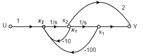
T(s)=
=
P1=2/s
P2=-8/s2
L1=-10/s
L2=-100/s2
The state equation will be
 =x2
=x2
 =-10x2-100x1+u
 =
= +
+
Q8) Find the state equation from the given differential equation

A8)
Let y=x1
 =
= =x2
=x2
 =
= =x3
=x3
 =
=
The above differential equation than becomes
 +6
+6 +11 x2+6 x1=u
 (t) =u-6
 (t)-11 x2-6 x1
Hence the state equation will be
 =
=  +
+ [u]
[u]
Q9) For the given data below compute the transfer function of the system
A= B=
B= C=[1 0] and D=[0]
A9)
The state equation will be
 =
= +
+
 =x1
=x1
 =-6x1-5x2
Equation (14) in section 4.1
 = C{[SI-A]-1B} + D
=C{ -
- }-1B+D
=C B+D
B+D
=[1 0] 
 + 0
+ 0
= +0
+0
 =
=
Q10) Obtain the state space representation of following mechanical system

A10)
The position and velocity state variables will be
x1=y1
x2=
x3=y2
x4=
The difference equation will be
M1 +B1
+B1 +K1y1+B2(
 -
- +K2(y1-y2)=0
M2 + K2(y2-y1) + B2(
 -
- )=u
)=u
Writing above equations in the form of state variables
M2 =u-K2(y2-y1) +-B2(
 -
- )
)
M1 =- B1
=- B1 -K1y1-B2(
 -
- -K2(y1-y2)
 = -(
= -( +
+ )x1- (
 ) x2+(
 )x3+
)x3+ x4
x4
 =
=  x1+
x1+ x2-
x2- x3-
x3- x4+
x4+
Now writing all the state equations
 =x2
=x2
 = -(
= -( +
+ )x1- (
 ) x2+(
 )x3+
)x3+ x4
x4
 = x4
= x4
 =
=  x1+
x1+ x2-
x2- x3-
x3- x4+
x4+
The matrix form for above equations is given below
 =
= 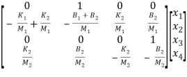 +
+ v(t)
v(t)
Q11) Obtain the eigenvectors of matrix A = 
A11)
For eigen values | iI-A|=0
| I-A|=
I-A|= -
-  =0
=0
| I-A| =
  =0
=0
| I-A| = (
 +4)2-1=0
| I-A| =
 2+8
2+8 +15=0
+15=0
The eigen values are
 1=-3,
1=-3,  2=-5
2=-5
Q12) Obtain the eigenvalues of system described as  =
= +
+ [u] and y= [1 0 0]
A12)
For eigenvalues | iI-A|=0
| I-A|=
I-A|= -
-  =0
=0
| I-A| =
  =0
=0
 3+6
3+6 2+11
2+11 +6=0
+6=0
( +1) (
+1) ( +2) (
+2) ( +3) = 0
Hence eigen values are  1=-1,
1=-1,  2=-2,
2=-2,  3= -3
3= -3
Q13) Find eigen vectors for the following system  =
=  +
+ [u] and y= [1 0 0]
A13)
Refer above que 12. The eigen values are  1=-1,
1=-1,  2=-2,
2=-2,  3= -3
3= -3
The eigen vectors will be
For  1=-1
1=-1
| I-A|X = 0
 = 0
= 0
-x1-x2 = 0
3x1 + x2 + 2x3 = 0
12x1+7x2+5x3=0
Solving above equations we get x1 = 1, x2= -1 as x3 = -1
Therefore, the eigen vectors are 
For  2=-2
2=-2
| I-A|X = 0
 = 0
= 0
-2x1-x2 = 0
3x1 + 2x2 + 3x3 = 0
17x1+7x2+4x3=0
Solving above equations we get x1 = 2, x2= -4 as x3 = -1
Therefore, the eigen vectors are 
For  3=-3
3=-3
| I-A|X = 0
 = 0
= 0
3x1+x2 = 0
3x1 + 3x2 + 2x3 = 0
12x1+7x2+3x3=0
Solving above equations we get x1 = 1, x2= -3 as x3 = 3
Therefore, the eigen vectors are 
Q14) Find the eigen vectors of the matrix A= 
A14)
For eigen values | iI-A|=0
| I-A|=
I-A|= -
-  =0
=0
| I-A| =
  =0
=0
| I-A| = (
 +3)2-1=0
| I-A| =
 2+6
2+6 +8=0
+8=0
 1=-2,
1=-2,  2=-4
2=-4
For  1=-2 the eigenvectors are
 -
-  x Xi=0
 -
-  x
x  = 0
= 0

 = 0
= 0
-x1+x2=0
For x1=1 x2=1 the equation above is satisfied.
Xi=
For  2=-4
2=-4
 -
-  x
x  = 0
= 0

 = 0
= 0
-x1-x2=0
For x1=1 x2= -1 the equation above is satisfied.
Xi=
Q15) Find the eigen vectors for the given matrix A=
A15)
For eigen values
| I-A|=
I-A|= -
-  =0
=0
| I-A| =
  =0
=0
| I-A| = (
 -3)(
-3)( -2)-2=0
| I-A| =
 2-5
2-5 +4=0
+4=0
 1=1,
1=1,  2=4
2=4
For  1=1 the eigenvectors are
 -
-  x Xi=0
 -
-  x
x  = 0
= 0

 = 0
= 0
-2x1+2x2=0
For x1=1 x2=1 the equation above is satisfied.
X1=
For  2=4
2=4
 -
-  x
x  = 0
= 0

 = 0
= 0
x1+2x2=0
For x1=2 x2= -1 the equation above is satisfied.
X2=
Arrange eigenvectors in a matrix P = 
P-1= -  =
=
The transformation matrix  =P-1AP
=
=
=
Q16) A system is represented by the state equation and output equation as
 =
=  +
+ u(t) and Y=[1 2]
Find the poles of the system and comment on stability?
A16)
A= 
The characteristic equation is given as
| I-A|=
I-A|= -
-  =0
=0
| I-A| =
  =0
=0
| I-A| = (
 +3) (
+3) ( +2)-2=0
| I-A| =
 2+5
2+5 +4=0
+4=0
 1=-1,
1=-1,  2=-4
2=-4
The poles are -1 and -4. Both on left half of s-plane so system is stable.
Q17) The state and output equation of LTI system is  =
=  +
+ [u] and y= [1 1 0]
 . Find the characteristic equation.
A17)
The characteristic equation is given as | I-A|=0
| I-A|=
I-A|= -
-  =0
=0
| I-A| =
  =0
=0
The characteristic equation is
 3-5
3-5 2-8
2-8 +2=0
+2=0
Hence poles are  1=-1,
1=-1,  2=-2,
2=-2,  3= -3
3= -3
Q18) A system is described by  =
= B=
B= C=[1 0] . Y = [1 0]. Check the controllability of the system?
A18)
[s] =[B AB]
= 
 ≠ 0 hence system is controllable.
Q19) A system is described by  =
= B=
B= C=[1 0] . Y = [1 0]. Check the observability of the system?
A19)
AT=  CT=
CT=
[Q]=[CT ATCT]
=

=

=
=0
 =0 hence not observable.
Q20) The state equation of the system is given below  =
= 
 +
+  u(t) . Y = [1 2]
 Comment on controllability?
A20)
A=  B=
B= 
Order of matrix n=2
[S] = [B AB]
=

= 
|S|= 0. Hence, system is not controllable.
Q21) The state space representation of a second order  = -x1+u and
  = x1-2x2+u. State whether the system is controllable or not?
A21)
 =
= 
 +
+  u(t)
u(t)
Order of matrix is n=2
[S] = [B AB]
=

= 
|S|= 0. Hence, system is not controllable.
Q22) A linear second order single input continuous time system is described as  = -2x1(t)+4x2(t) and
  = 2x1(t)-x2(t)+u(t). Comment on controllability?
A22)
 =
= 
 +
+  u(t)
u(t)
Order of matrix is n=2
[S] = [B AB]
=

= 
 ≠ 0 hence system is controllable.
Q23) What is the effect of pole zero cancellation on the controllability and observability of the system?
A23)
For an nth order system with distinct eigenvalues the transfer function be
T(s)= =[b0sm+b1sm-1+….+bm-1s+bm/[sn+a1sn-1+……..+an-1s+an]
=K(s- 1)( s-
 2)…….( s-
 m)/(s-
 1)( s-
 2)……( s-
 n)
n)
= 
ck are residue poles at s=
If the transfer function has identical pair of poles and zeros at  i=
i=  i
i
The effect of this cancellation of pole and zero on observability and controllability depends on the property of state variable.
- If the state variable is of the form below , then ci=0 will appear in control vector B and the state is uncontrollable.
 =
= 
 +
+  u
u
y=[1 1 1……..1] +b0u
+b0u
- On the other-hand if the state variables are of the form
 =
=  +
+
y=[c1 c2 c3…….. cn] +b0u
+b0u
Then then ci=0 will appear in output vector C and the state is shielded from observations.
- In LTI system if it has pole zero cancellation, the system will either be not controllable nor observable. But if the transfer function does not have any pole zero cancellations than the system can be represented by completely controllable and observable state model.