RTMNU ENGINEERING GRAPHICS-I
UNIT 4
Isometric Projections
Question bank
- What is meant by Isometric projection?
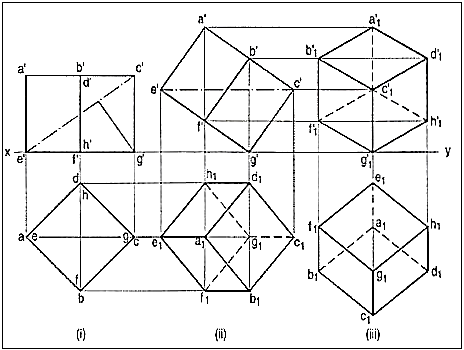
Isometric projection is a type of pictorial projection in which the three dimensions of a solid are not only shown in one view, but their actual sizes can be measured directly from it.
If a cube is placed on one of its corners on the ground with a solid diagonal perpendicular to the V.P., the front view is the isometric projection of the cube. The step-by-step construction is shown in fig.1.
2. Fig. 11 (i) shows the front view of a semi-circle whose surface is para1lel to the V.P. Draw its isometric view.
(i) Enclose the semi-circle in a rectangle. Draw the isometric view of therectangle [fig. 11 (ii) and [fig. 11 (iii)].
(ii) Using the four-centre method, draw the half-ellipse in it which is therequired view. The centre for the longer arc may be obtained as shown orby completing the rhombus.
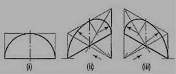
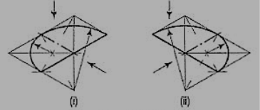
If the view given in fig. Is the top view of a horizontal semi-circle, its isometric view would be drawn as shown in figures.
3. Fig. 13 (i) shows the front view of a plane parallel to the V.P. Draw its isometric view.
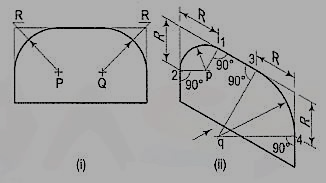
Figure 13
(i) The upper two corners of the plane are rounded with quarter circles. Enclose the plane in a rectangle.
(ii) Draw the isometric view of the rectangle. From the upper two corners of the parallelogram, mark points on the sides at a distance equal to R, the radius of the arcs. At these points erect perpendiculars to the respective sides to intersect each other at points p and q. With p and q as centres, and radii p1 and q3, draw the arcs and complete the required view.
4. Draw the isometric view of a square prism, side of the base 20 mm long and the axis 40 mm long, when its axis is (i) vertical and (ii) horizontal.
(i) When the axis is vertical, the ends of the prism will be horizontal. Draw theisometric view (the rhombus 1-2-3-4) of the top end [
Fig. Its sides will make 30°-angles with the horizontal. The length of the prism will bedrawn in the third direction, i.e. vertical. Hence, from the corners of therhombus, draw vertical lines 1-5, 2-6 and 3-7 of length equal to the lengthof the axis. The line 4-8 should not be drawn, as that edge will not bevisible. Draw lines 5-6 and 6-7, thus completing the required isometric view. Lines7-8 and 8-5 also should not be drawn. Beginning may also be made by drawinglines from the point 6 on the horizontal line and then proceeding upwards.
(ii) When the axis is horizontal, the ends will be vertical. The ends can be drawn in two ways as shown in fig. 14 and fig. 14 In each case, the length is shown in the direction of the third isometric axis.
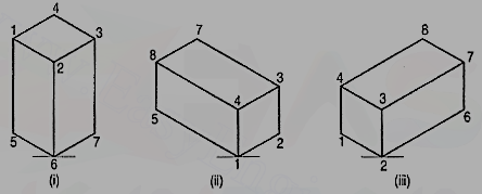
5. Three views of a block are given in fig. Draw its isometric view.
The block is in the form of a rectangular prism. Its shortest edges are vertical. Lines for these edges will be drawn vertical. Lines for all other edges which are horizontal, will be drawn inclined at 30° to the horizontal in direction of the two sloping axes as shown in fig.
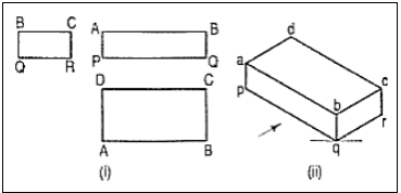
6. Three views of a block are given in fig. Draw its isometric view.
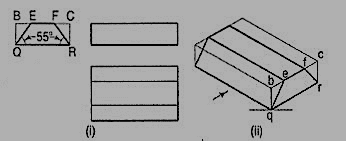
(i) Enclose the block in a rectangularbox.
(ii) Draw the isometric view of thebox [fig. 16 (ii)].
(iii) Mark points e and f on the line besuch that be = BE and fc = FC.
(iv) Complete the required view asshown.
7. Draw the isometricview of the frustum of the hexagonalpyramid shown in fig.
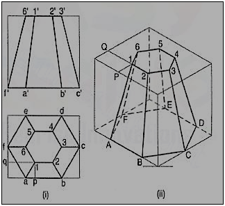
(i) Enclose the front view and the top view in rectangles.
(ii) Draw the isometric view of the rectangular box [fig. Locate the six points of the base of the frustum on the sides of the bottom of the box. The upper six points on the top surface of the box are located by drawing isometric lines, e.g. P1 and Q1 intersecting at a point 1.
(iii) Join the corners and complete the isometric view as shown.
Problem:
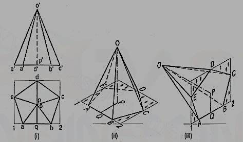
8 . Draw the isometric view of the pentagonal pyramid, the projections of which are given in fig.
(i) Enclose the base (in the top view) in an oblong.
(ii) Draw an offset oq (i.e. pq) on the line ab.
(iii) Draw the isometric view of the oblong and locate the corners of the base init [fig. 18 (ii)].
(iv) Mark a point Q on the line AB such that AQ = aq. From Q, draw a line QP equal to qo and parallel to 2C. At P, draw a vertical OP equal to o'p'.
(v) Join O with the corners of the base, thus completing the isometric viewof the pyramid.
Fig. Shows the isometric view of the same pyramid with its axis in horizontal position.
9. Draw the isometric viewof the cylinder shown in fig.
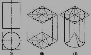
The axis of the cylinder is vertical; hence its ends are horizontal. Enclose the cylinder in a square prism.
Method I:
Draw the isometric view of the prism [fig. In the two rhombuses, draw the ellipses by the four-centre method. Draw two common tangents to the two ellipses. Erase the inner half of the lower ellipse and complete the required view.
Method II:
Draw the rhombus for the upper end ofthe prism [fig. And in it, draw theellipse by the four-centre method. From thecentres for the arcs, draw vertical lines oflength equal to the length of the axis, thusdetermining the centres for the lower ellipse.Draw the arcs for the half ellipse. Draw commontangents, thus completing the required view.
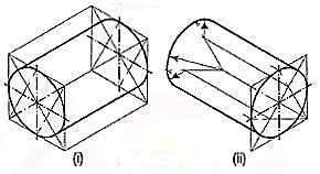
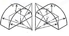
When the axis of the cylinder is horizontal, itsisometric view is drawn by method I as shown in fig.
Fig. Shows the view drawn by method II,but the axis is shown sloping in the other direction.
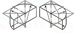
Fig. Respectively show the isometric views (drawn by method II) of ahalf-cylindrical disc with its axis in vertical and horizontal positions.
10. Draw the isometric projection of a sphere resting centrally onthe top of a square prism, the front view of which is shown in fig i.
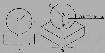
(i) Draw the isometric projection (using isometric scale) of the square prism and locate the centre P of its top surface
(ii) Draw a vertical at P and mark a point C on it, such that PC = the isometric radius of the sphere.
(iii) With C as centre and radius equal to the radius of the sphere, draw a circle which will be the isometric projection of the sphere.
SOLUTION
Figure (ii)
11. A hexagonal prism having the side of base 26 mm and the height of 60 mm is resting on one of the comer of the base and its axis is inclined to 30° to the H.P. Draw its projections and prepare the isometric view of the prism in the above stated condition.
(i) Draw the projections of the prism as shown in figure
(ii) Construct the isometric view as shown in figure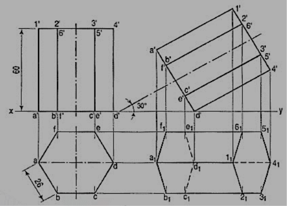
SOLUTION
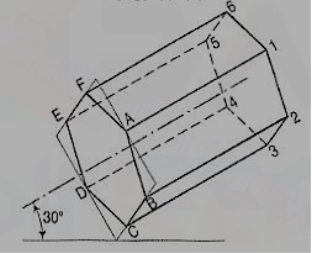
12. The orthographic projections of the object is shown in figure. Draw the isometric view of the object.
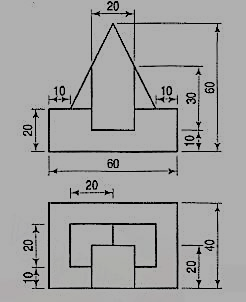
SOLUTION
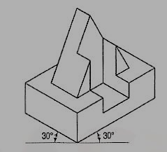
Figure 30