Unit - 4
Application of Flip-Flop
Q1) Explain ring counters.
A1)
Ring Counter
- It is a shift register counter whose output of the first flip flop is connected to the second and so on and the output of the last flip flop is fed back to the input of the first flip flop, thus named as ring counter.
- The data pattern in the register circulates as long as clock pulses are applied.
- The circuit below comprises of four D flip-flops which are connected synchronously.
- The data pattern repeats after every four clock pulses shown in the truth table.
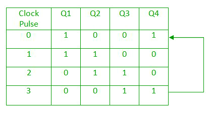
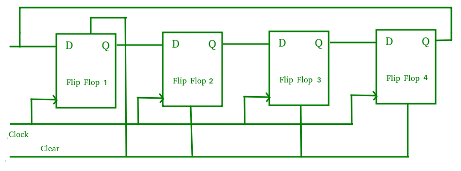
Fig. Ring counter
Q2) Explain twisted ring counter.
A2)
Twisted ring counter
It is also known as switch-tail ring counter, walking ring counter or Johnson counter. It connects the complement of the output of the last shift register to the input of the first register and circulates a stream of ones followed by zeros around the ring.

Here, we use Clock (CLK) for all the flip-flops.
Q3) Explain Sequence Generators and its steps.
A3)
- It is a sequential state machine which takes an input string of bits and generates an output 1 whenever the target sequence has been detected.
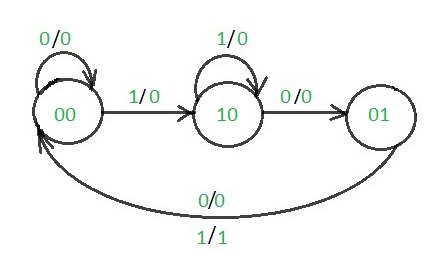
- In a Mealy machine, output depends on the present state and the external input (x).
- Hence the output is written outside the states, along with inputs.
- Sequence detector is of two types:
- Overlapping
- Non-Overlapping
- In an overlapping sequence detector the last bit of a sequence becomes the first bit of next one.
- In non-overlapping sequence detector the last bit of one sequence does not become the first bit of next one.
- Examples:
For non overlapping case
Input :0110101011001
Output:0000100010000
For overlapping case
Input :0110101011001
Output:0000101010000
The steps to design non-overlapping 101 Mealy sequence detector are:
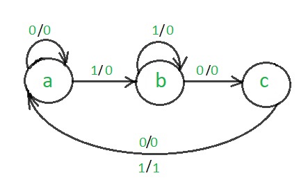
Step 1: Development of the state diagram –
The state diagram of a Mealy machine for a 101 sequence detector is:
Step 2: Assignment of the code–
Rule 1: States having the same next states for a given input condition should have adjacent assignments.
Rule 2: States that are the next states to a single state must be given adjacent assignments.
Rule 1 given preference over Rule 2.
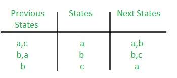
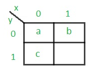
The state diagram after the code assignment is:
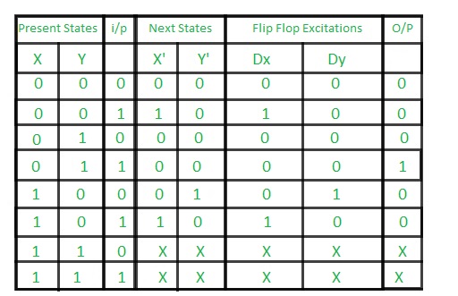
Step 3: Making Present State/Next State table –
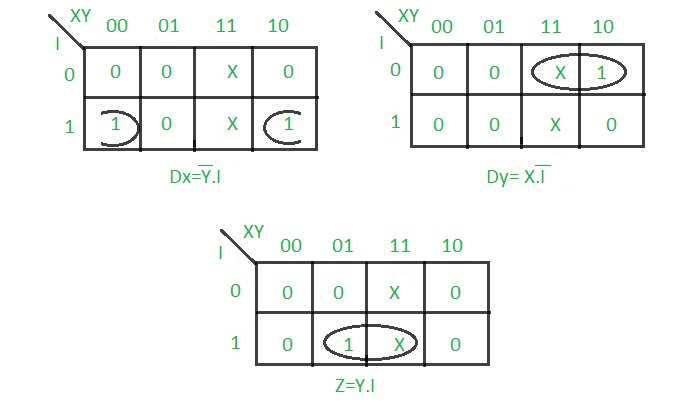
Step 4: Draw K-maps for Dx, Dy and output (Z) –
Step 5: Final implementation of the circuit –
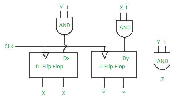
This is the desired circuit for a Mealy 101 non overlapping sequence detector.
Q4) Write a note on Ripple counters.
A4)
- In this universal clock is not used and only the first flip flop is driven by main clock and the clock input of rest of the following is driven by output of previous flip flops.

Fig. Asynchronous counter
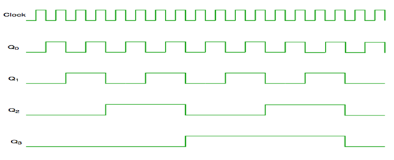
Fig. Timing diagram of Asynchronous counter
- It is seen from timing diagram that Q0 is changing as soon as the rising edge of clock pulse is encountered.
- Q1 is changing when rising edge of Q0 is encountered and so on.
- In this way ripples are generated through Q0,Q1,Q2,Q3 and therefore it is also called as a RIPPLE counter.
Q5) What are UP/Down counters? Explain with help of timing diagram?
A5)
Both Synchronous and Asynchronous counters are capable of counting “Up” or counting “Down”, but there is another more “Universal” type of counter that can count in both directions either up or down depending on the state of their input control pin and these are known as Bidirectional Counters.
Bidirectional counters, also known as Up/Down counters, are capable of counting in either direction through any given count sequence and they can be reversed at any point within their count sequence by using an additional control input as shown below.
The circuit above is of a simple 3-bit Up/Down synchronous counter using JK flip-flops configured to operate as toggle or T-type flip-flops giving a maximum count of zero (000) to seven (111) and back to zero again. Then the 3-Bit counter advances upward in sequence (0,1,2,3,4,5,6,7) or downwards in reverse sequence (7,6,5,4,3,2,1,0).
Generally, most bidirectional counter chips can be made to change their count direction either up or down at any point within their counting sequence. This is achieved by using an additional input pin which determines the direction of the count, either Up or Down and the timing diagram gives an example of the counter’s operation as this Up/Down input changes state.
Nowadays, both up and down counters are incorporated into single IC that is fully programmable to count in both an “Up” and a “Down” direction from any preset value producing a complete Bidirectional Counter chip. Common chips available are the 74HC190 4-bit BCD decade Up/Down counter, the 74F569 is a fully synchronous Up/Down binary counter and the CMOS 4029 4-bit Synchronous Up/Down counter.
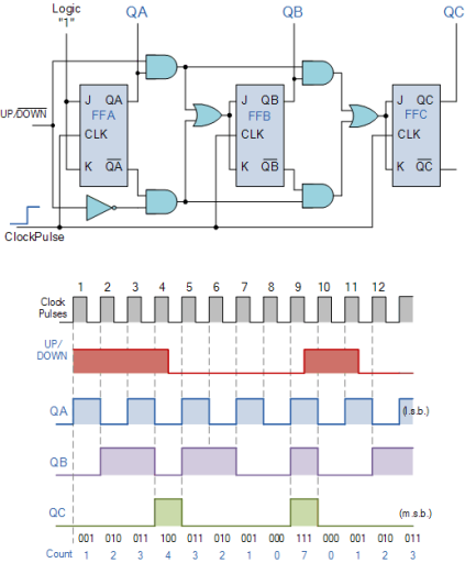
Fig: Up/Down Counter
Q6) Explain Synchronous counters
A6)
- It has one global clock which drives each and every flip flop and hence output changes in parallel.
- The advantage of synchronous counter over asynchronous counter is that it can operate on higher frequency and it does not have cumulative delay.

Fig. Synchronous counter
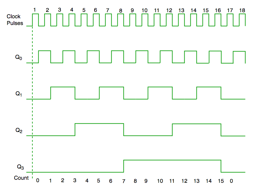
Fig. Timing diagram of synchronous counter
Q7) What is lockout condition in synchronous flip flops and suggest its remedy?
A7)
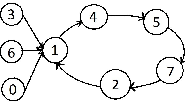
Sometimes a counter may find itself in some unused states, this happen when if next state of some unused state is again some unused one and if by chance the counter happens to find itself in some unused state and never arrives at in used state then this condition is called “Lock Out”.
The solution to above problem is
An additional circuit is required to ensure that “lock out” does not occur. The counter should be designed using the next state to be initial state from the unused state.
To avoid lock out condition the unused states are introduced in front of used states from the above state diagram the 1,4,5,6 and 7 is the sequence and unused states are 0,3 and 6 the states are introduced in front of us States 1,4,5 and 7 respectively.
Other than this we use a special circuit which always reset the counter whenever it got struck into an unused state.